
Subscribe to Our Youtube Channel
Related Manuals for Schwing S 20


Summary of Contents for Schwing S 20
- Page 1 Original operating instructions Truck-mounted concrete pump S 20/S 20 Hybrid - EN-...
- Page 2 Specify the machine type and the machine number stamped on the type plate of your machine when placing an order. Pass on these operating instructions when leaving the machine to someone else. Imprint: Editor: SCHWING GmbH Department: TDS 1 Address: Heerstr. 9-27...
- Page 3 2.6 Labelling SCHWING machines ........
- Page 4 1 Contents 2.7.5 Loading plan for S20/S20 Hybrid model........54 2.7.6 Placing boom .
- Page 5 1 Contents 2.13.6 Remote control ............80 2.13.7 Option box for special equipment .
- Page 6 1 Contents 3.3.2 Preparing the underride protection (special equipment) for concrete pump operation . . . 118 3.4 Your machine’s EMERGENCY STOP system ....... . 121 3.4.1 How to test the EMERGENCY-STOP buttons .
- Page 7 1 Contents 3.5.20 Configure values for VarioPressure ......... 152 3.5.20.1 Configure maximum values for VarioPressure .
- Page 8 1 Contents 3.7.6.1 Renault with automatic transmission ....... 203 3.8 Preheating the hydraulic system ......... 207 3.8.1 Cold start limit .
- Page 9 1 Contents 3.13 Working operation: Placing boom ........253 3.13.1 Safety .
- Page 10 3.18.2.3 Total permissible weight for SCHWING truck-mounted concrete pumps . . . 300 3.19 Emergency operation ........... 303 3.19.1 Safety instructions .
- Page 11 1 Contents 3.21.9 Interior cleaning ............331 3.21.10 Exterior cleaning .
- Page 12 1 Contents 3.26.1.11 Setting up the machine ......... 366 3.26.1.12 Cold start .
- Page 13 SCHWING drive line grease ........
- Page 14 1 Contents 4.8.3 Filling the empty oil box ........... 417 4.8.4 Purity of the hydraulic oil .
- Page 15 1 Contents 4.12 Drive lines of the pump drive ..........443 4.12.1 Lubrication .
- Page 16 1 Contents 4.16.7 Checking the seal of the slewing shaft ........477 4.16.8 Prolonged downtime .
- Page 17 4.21.2 Changing the fuses of SCHWING components ....... . 522...
- Page 18 4.23 Repair welding ............535 5.1 Radio control system SCHWING Control SC30 ......539 5.1.1...
- Page 19 1 Contents 5.1.21.1 Selecting the boom speed........571 5.1.22 Operating interruptions .
- Page 20 1 Contents 6.1.11.2 Safety shutdown in case of malfunction ......614 6.1.12 General: Operating error by the user ......... 615 6.1.13 General: Operating interruptions .
- Page 21 1 Contents 6.3.1.1 End hose - non-return valve ........657 6.3.1.2 Selector switch .
- Page 22 1 Contents 6.7.1 Preparations for operation ..........697 6.7.2 Turning the heating on .
- Page 23 1 Contents 6.13 Rotatable stowing box ..........731 6.13.1 General safety instructions for the stowing box .
- Page 24 1 Contents 98344974-S_20_hyb-ENIVZ.fm -...
- Page 25 2 Introduction This chapter contains the most important informa- tion about your machine, including: • Layout, • Conventions and • Handling Of these operating instructions. Trennblatt-Einleitung-EN.fm...
- Page 26 2 Introduction Trennblatt-Einleitung-EN.fm - 01.00.01...
- Page 27 In addition to the operating instructions, the general relevant legal and other rules on accident prevention of the country of operation should be observed. SCHWING GmbH is not liable for damages caused by a failure to observe these provisions and/or these operating instructions or by improper use of the machine!
- Page 28 The same also applies for the manufacturer of integrated motors used in our sta- tionary concrete pumps and trailer pumps. Other special pieces of equipment on your SCHWING machine may also have their own operating instructions. Please observe these documents, in addition to the SCHWING operating instruc- tions, in order to service and maintain these components properly.
- Page 29 If you still have any questions or doubts after reading the operating instructions, please do not hesitate to contact the customer service department at Schwing GmbH. If necessary, you can also organise individual training seminars. These operating instructions are also intended as reference work. The clear table of contents and the headers in the document were designed with that purpose in mind.
- Page 30 2.2 Structure of the operating instructions 2.2.2 Contents of the individual chapters in these operating instructions Introduction This chapter is intended to familiarise you with your machine. It contains, for example, the technical specifications, a short description and an overview of the machine. Operation In this chapter, you will find descriptions of all machine operating procedures, from commissioning to working operation and cleaning to decommissioning.
- Page 31 2.2 Structure of the operating instructions 2.2.3 Page layout of the operating instructions Header A dynamic column title is contained in the header on the outer edge of the page. The column title shows the corresponding sub-chapter currently being read, along with the chapter number and title.
- Page 32 2.2 Structure of the operating instructions 2.2.4 Structure of safety instructions In these operating instructions, safety instructions are placed in front of certain sec- tions to warn readers of dangers that could cause potential personal injury or ma- terial danger. The measures described to avert these dangers must be adhered to.
- Page 33 2.2 Structure of the operating instructions 2.2.6 Warning of material damage The following safety instructions describe the meaning of the signal word for mate- rial damage. ACHTUNG! Achtung! Material damage! Damage to your own machine or other objects. Describes how the material damage can be avoided. 2.2.7 Additional information The following symbol indicates useful tips and recommendations, as well as infor-...
- Page 34 2.2 Structure of the operating instructions Aufbau-BA-EN.fm - 01.05.01...
- Page 35 You must have clearly understood the contents of this chapter before reading the rest of the manual. Should you have any questions regarding the safety instructions, please contact Schwing’s customer service. 2.3.1 Safety instructions for working with the placing boom...
- Page 36 2.3 General safety instructions Fig. 2 Placing boom in backwards position GEFAHR! Danger! Danger to life due to the machine toppling! It is prohibited to lift loads with the placing boom as this can cause the machine to become unstable and topple over! The machine can cause death to people.
- Page 37 2.3 General safety instructions Fig. 4 Danger zone of placing boom WARNUNG! Warning! Danger of injury in the danger zone of the placing boom! A drop in pressure or lack of attention when moving the placing boom can lead to serious injuries or death.
- Page 38 2.3 General safety instructions Allgemeine_Sicherheitshinweise-EN.fm - 01.00.00...
- Page 39 2.4.1 Declaration of conformity SCHWING declares that the machine placed on the market in the European Eco- nomic Area complies with the relevant EC directives. We confirm this by issuing a declaration of conformity and affixing a CE mark to the machine.
- Page 40 Complete list of the applied national standards and technical specifications, see »Ref- erences in DIN EN 12001 conveying, spraying and placing machines for concrete and mortar — Safety requirements«, as well as the SCHWING factory standard. Noise emission Installed effective output...
- Page 41 Complete list of the applied national standards and technical specifications, see »Ref- erences in DIN EN 12001 conveying, spraying and placing machines for concrete and mortar — Safety requirements«, as well as the SCHWING factory standard. Noise emission P hydraulic = kW (hydraulic drive)
- Page 42 CE marking and declaration of conformity only apply to design and scope of deliv- ery of the machine delivered ex works. Making changes to the machine without the approval of SCHWING, in addition to using accessories without the approval of SCHWING, shall cause both to lose their validity.
- Page 43 • Improper operation by machine operators without adequate training or instruc- tion • Using concrete pipelines that are not approved by SCHWING • Not performing the boom inspections and corresponding repairs on time See “Maintenance” chapter for restrictions One construction job is generally defined as one extension and retraction cycle.
- Page 44 In the event of damages of any kind, the entire machine must be inspected. Contact SCHWING in the event of operations outside of the indicated reference values The following applies to all SCHWING machines: Fresh concrete +15 °C...
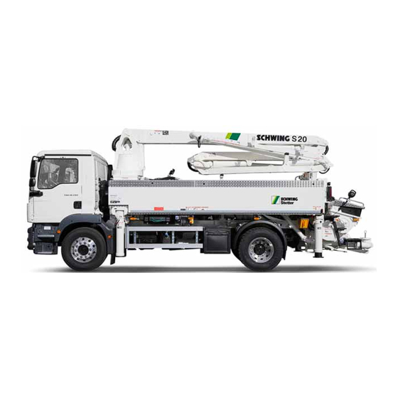
- Page 45 2.6 Labelling SCHWING machines Labelling SCHWING machines The most common abbreviations and their meanings are listed and explained here. 2.6.1 Truck-mounted concrete pumps S 24 X SCHWING approx. vertical reach in m X-outrigger S 31 XT SCHWING approx. vertical reach in m...
- Page 46 2.6 Labelling SCHWING machines Z-folding + Roll-folding + Telescoping 36 R approx. vertical reach in m Roll-folding 43 RZ approx. vertical reach in m Roll-folding + Z-folding 2.6.3 Marking of concrete pumps P 2020 - 120 / 80 (Concrete) Pump...
- Page 47 2.6 Labelling SCHWING machines The type plate of the placing boom is located at the front left side of the first boom section in the direction of travel. Example (Fig. 7) applies to 5-part placing booms; the plate for 4-part placing booms has a similar design.
- Page 48 VECTOR control system, see (“VECTOR control system” on page 125). Scroll down through the "Functions" menu to the “Machine data” or “Vehicle data” sub-menus and record the data here: SCHWING - machine technical data Vehicle data Mach. no.: Manufacturer: Mach.
- Page 49 Max. hydraulic oil pressure P 2025-5-120/80 TC RB P P 2525-6-120/85 TC RB P Table 1 SCHWING pump kits Column 1: Concrete pump type, see (“Marking of concrete pumps” on page 44). Column 2: maximum delivery rate of the hydraulic pump(s) in l/min Column 3: configured pressure cut-off Column 4: maximum theoretical concrete delivery rate in m³/h...
- Page 50 2.6 Labelling SCHWING machines Maschinenkennzeichnung-EN.fm - 01.05.03...
- Page 51 2.7 Technical data Technical data This chapter contains the following data related to your machine: • Dimensions • Supporting forces • Ranges of the placing boom (working area) • Positions of the most important components on your machine 2.7.1 Dimensions of vehicle body / work area Information The supporting forces specified are maximum values.
- Page 52 2.7 Technical data 2.7.2 Vehicle body: S20 Hybrid Length of end hose Vertical reach 23.46 m 19.50 m Range 19.45 m 15.80 m Minimum unfolding height 4.89 m 3.90 m Number of arms Nominal size of pumping line 125 mm 125 mm (100 mm upon request) Support width in front 4.69 m / 5.96 m depending on...
- Page 53 2.7 Technical data Fig. 9 Model S20 Hybrid 2.7.3 The main components of the machine TechDat-S20_hyb-EN.fm - 01.05.01...
- Page 54 Water box Placing boom with pumping line see Pumping cylinder (chap. 2.7.5) Rear outrigger Rock valve Concrete filling hopper Chassis frame with SCHWING pump drive Front X - outrigger Slewing cylinder Turret Differential cylinder Rotary drive Control block Oil box Water case TechDat-S20_hyb-EN.fm - 01.05.01...
- Page 55 2.7 Technical data 2.7.4 Placing boom: Working range for S20 Hybrid 00137_ Arbeitsbereich Fig. 11 Working range for S20 Hybrid TechDat-S20_hyb-EN.fm - 01.05.01...
- Page 56 2.7 Technical data 2.7.5 Loading plan for S20/S20 Hybrid model Fig. 12 Loading plan for S20/S20 Hybrid model TechDat-S20_hyb-EN.fm - 01.05.01...
- Page 57 2.7 Technical data 2.7.6 Placing boom Fig. 13 Placing boom Caption (Fig. 13 Placing boom) Pos. Description Pos. Description Chassis frame End hose Cylinder A Gate valve system Boom section 1 Concrete pump kit Cylinder B Pumping line Boom section 2 Base frame Cylinder C Joint “A”...
- Page 58 2.7 Technical data 2.7.7 Technical data for the electric motor (optional for S20 Hybrid model) An electric motor with the following performance data is used as the power source for the S20 Hybrid variant. Engine FCMP 250M - 4 / PHE Design IM B35 / IM 2001 50 Hz...
- Page 59 2.8 Reversing the pump kits Reversing the pump kits The pump kits on SCHWING machines can be reversed in part. Reversing means changing from rod-side to piston-side application or vice versa. Contact SCHWING’s customer service for more information! WARNUNG! Warning! Risk of explosion due to improper reversing! Severe injuries or even death due to explosive release of pressure.
- Page 60 Example 2: This is a concrete pump that may be driven by the rod side or the piston side. The lower value refers to the maximum possible pumping pressure for rod-sided application. The upper value refers to the maximum possible pumping pressure for piston-sided application. Information SCHWING delivers concrete pumps with rod-side application. Umklemmen-Pumpenbatterie-EN.fm - 01.05.02...
- Page 61 2.9 Assembly groups and designations Assembly groups and designations This chapter contains an overview of the main assembly groups for your machine and their respective positions. 2.9.1 Base frame The base frame carries the concrete pump and the placing boom of the truck- mounted concrete pump.
- Page 62 2.9 Assembly groups and designations 1 - drive motor 2 - vehicle gearbox 3 - distribution manual transmission gear 4 - hydraulic pumps 5 - rear axle Fig. 16 Distribution manual transmission gear 2.9.3 Concrete pump The concrete pump is a two-cylinder piston pump with a rock valve. The most important assembly groups (Fig.
- Page 63 2.9 Assembly groups and designations Function: The MPS is a momentary drop in pressure. The hydraulic oil pressure in the concrete pump system is reduced at the same mo- ment as the differential cylinders switch from suction stroke to pressure stroke. The hydraulic accumulator required for the MPS control is charged via an individu- ally adjustable hydraulic pump.
- Page 64 2.9 Assembly groups and designations Fig. 17 Concrete pump 2.9.6 Control The placing boom is controlled using “proportional valves”. Its pilot control is elec- tro-hydraulic. Concrete pumps and agitators are electro-pneumatically pilot controlled. The electrical system is supplied by the vehicle electronics, and the compressed air for the electro-pneumatic pilot control is extracted from the vehicle air reservoir.
- Page 65 2.9 Assembly groups and designations 2.9.7 Placing boom and outrigger The placing boom has a "roll-folding" or “Z-folding” design. Information Special features of the S 65 SXF model The outriggers for model S 65 SXF contain folding segments on the front outrig- gers, which first have to be folded out to support the machine.
- Page 66 2.9.13 VarioPressure (special equipment) The “VarioPressure” accessory makes it possible to adjust the pumping pressure of the SCHWING pump at any time based on the situation at the jobsite. “VarioPressure” can also be used to protect equipment connected to the pump, such as concrete pumping hoses.
- Page 67 Fig. 18 Noise level The indicated value represents an average value for the respective series, plus a safety margin. SCHWING guarantees that this value will not be exceeded by newly delivered, ex works machines. Information Regarding noise emissions, please observe the regionally applicable reductions in operating time! Geraeuschemission-BPL-EN.fm - 01.12.02...
- Page 68 2.10 Noise information for truck-mounted concrete pumps 2.10.2 The highest sound pressure level (L The sound pressure level is a measure of the sound emissions in the workplace. In this case, the Machine Directive prescribes that the highest sound pressure level be measured at a distance of 1 m from the machine surface and 1.6 m across the ground, which must be indicated in the operating instructions.
- Page 69 S 20 90 dB(A) 4 m from the front, on the left in the driving direction 117 dB(A) S 20 Hybrid E 90 dB(A) 2.8 m from the front, on the left in the driving direction 117 dB(A) S 20 Hybrid D 90 dB(A) 2.8 m from the front, on the right in the driving direction...
- Page 70 2.10 Noise information for truck-mounted concrete pumps Geraeuschemission-BPL-EN.fm - 01.12.02...
- Page 71 Pictographs without text Different warning and information signs in the national language are located on your SCHWING concrete pump, in addition to textless pictographs. An overview of all signs without text can be found below. Pictographs without text are situated on various control elements on the machine.
- Page 72 2.11 Pictographs without text 2.11.1 Pictographs Concrete pump Start-up damping Delivery rate Start-up damping on / off adjustment Pumping - 0 - Sucking 10144573 10187511 10144566 98362082 Agitator Concrete pump Isolation valve Isolation valve Pump operation (P) - 0 - Suck - 0 - Pump open close...
- Page 73 2.11 Pictographs without text Speed adjuster Water pump Compressor CE signs 10086507 10158389 10144568 10148919 Main switch battery Delivery note box - No tread surface on - off 98394724 98393988 Stowing box EASy display Underride protection device Up - 0 - Down 10191719 10200927 98361549...
- Page 74 2.11 Pictographs without text Lifting eye; 98363577* 10163380 Attention! Example values for: • Horizontal trailer load • Vertical trailer load 98381870* 98381419* Warning: hot surface 98380738* * = For stationary concrete pumps only Textlose-Bildzeichen-EN.fm - 01.04.00...
- Page 75 2.12 Individual pictographs 2.12 Individual pictographs These signs are only used for specific machine types. The following signs are sort- ed according to machine types. 2.12.1 Tabular determination of the required supporting surface Fig. 21: 98336345 2.12.2 Signs and labels for the supporting forces on the machine outriggers S 24 X Sign on the front outrigger Sign on the rear outrigger Individuelle-Bildzeichen-S20_hyb-EN.fm - 01.01.02...
- Page 76 2.12 Individual pictographs 2.12.3 Operation plate for emergency operation on the placing boom control station • 1-6: Placing boom control • 7: Switching: Boom -0- Outrigger • 8: Switching: Compressor -0- water pump Fig. 22: Operation plate for emergency operation 2.12.4 Operation plate on the outrigger control block Direction right: Outriggers on -0- off Fig.
- Page 77 2.13.1 Overview Fig. 25 Overview Caption (Fig. 25 Overview) Pos. Description • Key-operated switch for SCHWING control Switch cabinet of the control • Gearshift lever for distributor gearbox (special equipment) Inspection glass for hydraulic oil level...
- Page 78 2.13 Control, warning and steering elements 2.13.2 Control station for operating mode: Emergency operation The terminal box for the VECTOR control system (Fig. 29) and the control station for the hydraulic emergency operation of the S20 / S20 Hybrid (Fig. 26:) are located in lockable housings on the right side of the machine (Fig.
- Page 79 2.13 Control, warning and steering elements 2.13.3 Machine control via electric drive (S20 Hybrid model) The two switch cabinets (3) for the electric drive, the cable drum (1) and the CEE plugs for the current supply (2) are located on the left-hand side of the machine for the S20 Hybrid model.
- Page 80 2.13 Control, warning and steering elements 2.13.4 Control Fig. 28 Control The hydraulic emergency control (1) and the terminal box of the electrical control (2) are located on the right side of the machine (Fig. 28) in lockable housings. Caption (Fig. 28 Control) Pos.
- Page 81 2.13 Control, warning and steering elements 2.13.5 Switch cabinet for VECTOR control (See “VECTOR control system” on page 125) Fig. 29 VECTOR switch cabinet Caption (Fig. 29) Pos. Designation Display Keypad Selector switch: Operating modes Button: VECTOR control ON Switch: EASy work area Switch: EASy OFF Key-operated switch: EMERGENCY STOP bypass Kontroll-Warn-Steuerelemente-S20_hyb-EN.fm - 01.02.02...
- Page 82 2.13 Control, warning and steering elements 2.13.6 Remote control During normal operation, a truck-mounted concrete pump is not operated via the remote control unit. The SC 30 digital radio equipment was specially developed for controlling truck- mounted concrete pumps with a placing boom. The radio system includes: •...
- Page 83 2.13 Control, warning and steering elements 2.13.7 Option box for special equipment The option box is located in one of the tool cabinets near the VECTOR control switch cabinet. Fig. 32 Old option box Fig. 33 New option box Caption (Fig. 32) / (Fig. 33) Pos.
- Page 84 2.13 Control, warning and steering elements 2.13.8 Local control The local control unit is integrated into the upper section of the supply control. Fig. 34 Old local control Fig. 35 New local control Caption (Fig. 34) / (Fig. 35) Pos. Description Function of Motor button Speed adjuster...
- Page 85 2.13 Control, warning and steering elements 2.13.9 Supply control tail end of vehicle, right Deviations are possible depend- ing on the equip- ment variants. Fig. 36 Old supply control Fig. 37 New supply control Caption (Fig. 36) / (Fig. 37) Pos.
- Page 86 2.13 Control, warning and steering elements 2.13.10 Right tail end of vehicle: Back of supply control (deviations are possible, depending on the version of the machine) Fig. 38 Caption (Fig. 38 ) Pos. Description Power outlet for vibrator Lubrication point of rock and agitator Kontroll-Warn-Steuerelemente-S20_hyb-EN.fm - 01.02.02...
- Page 87 2.13 Control, warning and steering elements 2.13.11 Right tail end of vehicle, chamber valve and water box emptying Fig. 39: Components on tail end of vehicle (right) Caption (Fig. 39: Components on tail end of vehicle (right)) Pos. Description Pos. Description Control lever chamber valve: Drain cock chamber valve...
- Page 88 2.13 Control, warning and steering elements 2.13.12 Right tail end of vehicle Fig. 40 Water pump and rolling equipment for high-pressure hose Caption (Fig. 40 Water pump and rolling equipment for high-pressure hose) Pos. Description High-pressure water pump Rolling equipment for high-pressure hose Kontroll-Warn-Steuerelemente-S20_hyb-EN.fm - 01.02.02...
- Page 89 2.13 Control, warning and steering elements 2.13.13 Special control: Pumping piston change This control station is located at the rear of the truck-mounted concrete pump, above the concrete filling hopper. Fig. 41 Pumping piston change on rear boom support Caption (Fig. 41 Pumping piston change on rear boom support) Pos.
- Page 90 2.13 Control, warning and steering elements 2.13.14 Outrigger Description of the control levers at both sides of the vehicle. For configuration, see symbols on the machine, e.g.: Outrigger front horizontal: 4 Button outrigger release RETRACT - 0 - EXTEND Supporting leg front vertical: 5 Spirit level RETRACT - 0 - EXTEND Supporting leg rear vertical:...
- Page 91 2.13 Control, warning and steering elements 2.13.14.1 On the left in the direction of travel Fig. 42 On the left in the direction of travel 2.13.14.2 On the right in the direction of travel Fig. 43 On the right in the direction of travel Kontroll-Warn-Steuerelemente-S20_hyb-EN.fm - 01.02.02...
- Page 92 2.13 Control, warning and steering elements 2.13.15 Remote control Information A separate description of the remote control used is provided in chapter “Remote control” on page 537 of these operating instructions. Kontroll-Warn-Steuerelemente-S20_hyb-EN.fm - 01.02.02...
- Page 93 2.14 Switches on the instrument panel This chapter describes the switches in the driver’s cab, which are required for con- trolling the SCHWING machine. The information is sorted according to vehicle manufacturer. Information The machine has control devices already provided for various special equipment.
- Page 94 2.14 Switches on the instrument panel 2.14.2 MAN Cockpit-MAN-01.wmf Fig. 45 MAN fittings Caption for (Fig. 45) Pos. Description Function of Switch position I = VECTOR control Switch position 0 = VECTOR control Switch position II = Turn drum (truck mixer concrete pump only) Pilot light for VECTOR control system ON/OFF rotating warning light...
- Page 95 2.14 Switches on the instrument panel 2.14.3 Scania schalterPD-Scania-01.wmf Fig. 46 SCANIA fittings Caption (Fig. 46 SCANIA fittings) Pos. Description Function of VECTOR control Pilot light for VECTOR control system ON/OFF Distribution manual transmission gear Switch position 0 Machine in drive mode Switch position 1 Machine pumping mode Outrigger lighting...
- Page 96 2.14 Switches on the instrument panel 2.14.4 Iveco cockpit-IVECO-01 Fig. 47 IVECO fitting Caption for (Fig. 47) Pos. Description Function of VECTOR control ON/OFF Pilot light for VECTOR control system ON/OFF Schalter-im-Armaturentraeger-EN.fm - 01.03.00...
- Page 97 2.14 Switches on the instrument panel 2.14.5 Renault Fig. 48 Renault fitting Caption for (Fig. 48) Pos. Description Function of VECTOR control ON/OFF Pilot light for VECTOR control system ON/OFF Schalter-im-Armaturentraeger-EN.fm - 01.03.00...
- Page 98 2.14 Switches on the instrument panel 2.14.6 Explanation of the "EXT" switch on SCANIA vehicles Before you can control the machine using a remote control, you must press the "EXT" button (4) in the cab of your SCANIA vehicle. Only then is it possible to start the vehicle's engine using the vector remote control unit, for example.
- Page 99 3 Operation This chapter describes: • All of your machine’s operating modes • Safe and proper handing • Safe and economical operation Trennblatt_Kapitel-Betrieb-EN.fm...
- Page 100 3 Operation Trennblatt_Kapitel-Betrieb-EN.fm - 01.00.00...
- Page 101 3.1 Readying the machine for operation Readying the machine for operation Information Some of the work described below should be carried out expediently at the depot before driving the machine to the installation site. • Perform maintenance according to the maintenance schedule (lubrication ser- vice, etc.).
- Page 102 3.1 Readying the machine for operation ACHTUNG! Attention! Risk of explosions due to hot components! Hot surfaces can cause fuel to ignite, which can in turn lead to explosions. When refuelling, switch off the motor and auxiliary heating. In addition, observe the safety regulations for handling fuel.
- Page 103 3.1 Readying the machine for operation Fig. 51 Connect “C” hose and open gate valve Close the gate valve in the suction pipe of the water pump (6) (Fig. 50 Perform- ing maintenance work)! Connect the "C" hose to the coupling and open the gate valve (1) (Fig.
- Page 104 3.1 Readying the machine for operation 3.1.2 Function of the ball valves on the CP control block: The ball valve (1) (Fig. 55 CP control block) on the CP control block has to be lo- cated in the operating position before you can begin pumping. The ball valve is open in the operating position.
- Page 105 3.1 Readying the machine for operation 3.1.3 Checking the hydraulic oil level Check the oil level of the hydraulic oil box on the inspection glass (1) (Fig. 56 Oil box). Check the oil level only when the oil is cold, before you start the hydraulic pump drive for the first time prior to daily use.
- Page 106 3.1 Readying the machine for operation Information The diagnosis system of the "VECTOR control" can monitor the oil level as a spe- cial equipment. It reports an error when the oil level drops too low. 3.1.4 Grid assembly in concrete filling hopper ...
- Page 107 3.1 Readying the machine for operation 3.1.5 Preparing the VECTOR control system The duty cycle also starts with setting up the machine. To do this, operating mode: “LOCAL” is selected. In order to drive the machine using the local control unit, the plug must always be attached to the transmitter or to the cable remote control on the switch cabinet.
- Page 108 3.1 Readying the machine for operation 3.1.6 Preparing the electrical connection (for S20 Hybrid model) 3.1.6.1 Safety instructions and general information An electric motor is used as the power source for the S20 Hybrid variant. Observe the following instructions. Information Before commencing any type of work, always observe the “Safety manual –...
- Page 109 3.1 Readying the machine for operation Electric motor Supply line max. 100 m Fuse [A] 4 x 16 4 x 25 4 x 35 4 x 50 4 x 70 4 x 95 4 x 120 4 x 185 4 x 240 3.1.6.2 Checking the rotational direction of the electric motor (control without phase sequence monitoring)
- Page 110 3.1 Readying the machine for operation 3.1.6.4 Technical data for the electric motor The following technical data applies to the electric motor being used: Engine FCMP 250M - 4 / PHE Design IM B35 / IM 2001 50 Hz 60 Hz Engine power 55 kW 66 kW...
- Page 111 3.2 Driving operation Driving operation This chapter only describes measures for making the SCHWING machine ready to drive. Follow all preparatory measures for driving on public roads. GEFAHR! Danger! Danger to life when driving with placing boom folded out! Fatal injuries while driving with placing boom folded out.
- Page 112 3.2 Driving operation WARNUNG! Warning! Personal injury due to unsecured load! Fatal injuries are possible. Store loads securely. Store equipment and accessories securely. Securely lock toolboxes and drawers. Close locks and remove keys. Move all foldable equipment (e.g. steps, (Fig. 59 Folding steps)) into the trans- port position.
- Page 113 3.2 Driving operation Fig. 59 Folding steps Fig. 60 Reflector Fahrbetrieb-EN.fm - 01.07.04...
- Page 114 3.2 Driving operation 3.2.2 Trailing axle Information Observe the operating instructions of the vehicle or axle manufacturer. Depending on the vehicle, the machine can be equipped with trailing axles from various manufacturers. To guarantee stability during pumping, the bellows of this axle can be vented, see (“Pneumatic suspension / Levelling”...
- Page 115 3.2 Driving operation 3.2.3 Transporting people and goods Mobile concrete pumps and placing booms are self-propelled machines. Self-propelled machines are motor vehicles which, according to their design and the special equipment firmly attached to the vehicle, are intended and suitable for carrying out work, but not for transporting people or goods.
- Page 116 3.2 Driving operation Fahrbetrieb-EN.fm - 01.07.04...
- Page 117 3.3 Installation site of the machine Installation site of the machine SCHWING recommends not driving onto the jobsite until you have been briefed by an “instructor” authorised by the site management:: • Before driving onto the jobsite, determine the exact location on the site.
- Page 118 3.3 Installation site of the machine • Maintain the prescribed safety distance between high-voltage lines and all plac- ing boom positions (Table 2 Safety distances for high-voltage lines), (Fig. 61 Safety distance for high-voltage line). Nominal voltage Minimum distance up to 1 kV 1.0 m 1 kV to 110 kV 3.0 m...
- Page 119 During bad weather, the placing boom must be folded together into transport posi- tion. Information As of May 2012, SCHWING concrete pumps are equipped with a connection option for an earthing cable. Before connecting the earthing cable, the supporting surfaces must be bare metal! The earthing cable and conductive metal rod are not included in the scope of deliv- ery of your SCHWING machine.
- Page 120 3.3 Installation site of the machine Fig. 63 Rock valve support 3.3.2 Preparing the underride protection (special equipment) for concrete pump oper- ation The underride protection (1) is in the drive position (Fig. 64). Release both locks (2) on the underride protection (Fig. 65). ...
- Page 121 3.3 Installation site of the machine Fig. 66 Chain fastener Fig. 67 “A” = secured / “B” = released Fig. 68 Underride protection in operating position Aufstellungsort-waehlen-EN.fm - 01.02.01...
- Page 122 3.3 Installation site of the machine Aufstellungsort-waehlen-EN.fm - 01.02.01...
- Page 123 3.4 Your machine’s EMERGENCY STOP system Your machine’s EMERGENCY STOP system GEFAHR! Danger! Risk of accident due to inoperative EMERGENCY-STOP button! Operating the machine with a defective EMERGENCY STOP system is prohibited and can lead to fatal accidents. Prior to any working operation, check the function of all EMERGENCY STOP buttons. Information Inform any relevant persons of the positions of the EMERGENCY STOP buttons on your machine in order to be able to react in emergency situations.
- Page 124 3.4 Your machine’s EMERGENCY STOP system 3.4.1 How to test the EMERGENCY-STOP buttons Switch on the VECTOR control system. Select the “REMOTE” operating mode. Use the radio remote control to diagnose and release the VECTOR control sys- tem after interrupting the EMERGENCY STOP.
- Page 125 3.4 Your machine’s EMERGENCY STOP system 3.4.3 Restarting the machine after an EMERGENCY STOP • Remedy the fault. • Set all engaged selector switches for the active control unit to the "0 or centre position" and unlock all EMERGENCY STOP buttons. Otherwise, it will not be possible to start up the machine! •...
- Page 126 3.4 Your machine’s EMERGENCY STOP system Not-Halt-System-EN.fm - 01.05.01...
- Page 127 3.5 VECTOR control system VECTOR control system 3.5.1 Introduction / Overview The VECTOR control unit includes a remote control system (chap. 5) and an inte- grated diagnostic system. The diagnosis system monitors the machine and controls for faults and improper operating states.
- Page 128 3.5 VECTOR control system 3.5.2 Contents 3.5.1 Introduction / Overview 125 3.5.2 Contents 126 3.5.3 Start screen 128 3.5.4 Commissioning 129 3.5.5 Operating mode: Local 130 3.5.6 Operating mode: Remote 132 3.5.7 Operating mode: Pumping piston change 134 3.5.8 Operating mode: Maintenance operation 136 3.5.9 Safety 137 3.5.9.1...
- Page 129 3.5 VECTOR control system 3.5.26.6 R = Remote (remote control system) 174 3.5.26.7 S = system (memory, multi-fuse, interfaces) 176 3.5.26.8 Economic Engine Control (EEC) 178 3.5.26.9 Automatic speed control (pump operation) 178 3.5.26.10 Automatic speed control (boom operation) 179 3.5.27 Abbreviations used 179 3.5.28 Explanations 180 VECTOR-EN.fm - 01.23.00...
- Page 130 3.5 VECTOR control system 3.5.3 Start screen Fig. 71 Display overview Caption (Fig. 71) Position Start screen Function of Power take off rotational speed Hydraulic oil temperature Oil cooler active Control status Please start control Control ready for operation No zero position for operating switch EMERGENCY STOP active Awaiting input...
- Page 131 3.5 VECTOR control system 3.5.4 Commissioning The electrical VECTOR control can only be switched on after proper activation of the drive circuit: • Switch on vehicle ignition • Disengage the vehicle’s drive gear (neutral position) • Engage parking brake • Switching on the power take-off •...
- Page 132 3.5 VECTOR control system Fig. 72 VECTOR start screen Fig. 73 Switch cabinet for VECTOR control 3.5.5 Operating mode: Local Symbol flashing: Operating mode ready for release! Activate the "LOCAL" operating mode using switch (3) on the switch cabinet of the VECTOR control system (Fig. 74). Release the "LOCAL"...
- Page 133 3.5 VECTOR control system Fig. 74 Fig. 75 Start screen Fig. 76 Local control Fig. 77 Local control keypad VECTOR-EN.fm - 01.23.00...
- Page 134 3.5 VECTOR control system 3.5.6 Operating mode: Remote Symbol flashing: Operating mode ready for release! Activate the "REMOTE" operating mode using switch 3 on the switch cabinet of the VECTOR control system (Fig. 78). Release the "REMOTE" operating mode with button S3 (control release or diagnostic horn) on the remote control.
- Page 135 3.5 VECTOR control system Fig. 79 Fig. 80 Local control Fig. 81 Local control keypad VECTOR-EN.fm - 01.23.00...
- Page 136 3.5 VECTOR control system 3.5.7 Operating mode: Pumping piston change Symbol flashing: Operating mode ready for release! Activate the "Pumping piston change" operating mode using switch 3 on the switch cabinet of the VECTOR control system (Fig. 82). Release the "Pumping piston change" operating mode with button (4).
- Page 137 3.5 VECTOR control system Fig. 83 Fig. 84 VECTOR-EN.fm - 01.23.00...
- Page 138 3.5 VECTOR control system 3.5.8 Operating mode: Maintenance operation For machines supplied within the European Economic Area, the VECTOR control system features the operating mode "Maintenance operation" as of software ver- sion V 1.40. In maintenance operation, the placing boom can slightly be lifted out of the trans- port position and lowered again without having to support the machine horizontally as required for working operation.
- Page 139 3.5 VECTOR control system 3.5.9 Safety 3.5.9.1 Vehicle engine: Start / Stop In order to prevent any functions from being triggered inadvertently, the vehicle mo- tor can only be started when all switches (except lighting) on the local and remote control units are in the neutral (0) position.
- Page 140 3.5 VECTOR control system 3.5.10 EMERGENCY STOP bypass When is an EMERGENCY-STOP bypass necessary? Bypassing the EMERGENCY STOP system is necessary if the electrical control system fails in order to move the machine into the transport position. 3.5.10.1 Special precautions for the machine operator The EMERGENCY STOP valves must be bypassed only in an extreme emergen- Working operation must be stopped immediately! This "emergency operation"...
- Page 141 3.5 VECTOR control system Information Excursus: The EMERGENCY STOP valves of the machine are open if not energised, meaning that: These valves will open in case of a defect in the EMERGENCY STOP system. The hydraulic fluid reaches the hydraulic tank without pressure. Initiated working move- ments are not carried out.
- Page 142 3.5 VECTOR control system 3.5.11 Control and check devices 3.5.11.1 Switch cabinet for VECTOR control Fig. 86 Switch cabinet for VECTOR control Caption (Fig. 86) Pos. Description Function of Display Control panel: Menu system Local Operating mode switch: Remote Pumping piston change Button: Control release Switch:...
- Page 143 3.5 VECTOR control system 3.5.11.2 Displays The following information is displayed in the menu system: (see “Start screen” on page 128 for the start screen) Pressing the button on the control panel displays additional menus with ad- ditional operating data. 3.5.11.3 Display screen: Concrete pump Fig.
- Page 144 3.5 VECTOR control system 3.5.11.4 Display screen: for slewing gear Fig. 88 “Slewing gear” screen Caption (Fig. 88) Pos. Description Function of Graphic display: Slewing gear range Slewing gear range (degrees) Rotational speed of power take-off (rpm) Hydraulic oil temperature (°C) 3.5.11.5 Status indicators in VECTOR control system The following conditions can be displayed in field (4) (Fig.
- Page 145 3.5 VECTOR control system 3.5.11.6 Operating mode screen The following operating modes can be displayed in field 5 (Fig. 89) of the display: Remote (radio or cable) Local Pumping piston change Teach mode Upon introduction of software version V1.40 and in case of CE equipment, the "Maintenance operation"...
- Page 146 3.5 VECTOR control system 3.5.12 Menu operation Basic functions of control panel (2) (Fig. 90): Fig. 90 When actuated, the function of the button is displayed by an symbol in the upper left corner of the display. Complete return to the start screen (initial screen). Scroll up one item in the menu selection.
- Page 147 3.5 VECTOR control system 3.5.13 Shortcuts 3.5.13.1 Manual contract adjustment for the LC display During adjustment, the contrast value, ranging from 0% to 99%, is shown on the display: Press buttons simultaneously: 3.5.13.2 Manual language selection for all displays (MMI language) Press buttons simultaneously: 3.5.13.3 Explanation of abbreviations...
- Page 148 3.5 VECTOR control system 3.5.14 Menu overview - main menu Figures are in English. Start screen Functions? see (“Sub-menus” on page 147). Functions? Pumping rate? Concrete pump see (“Sub-menus” on page 147). Pumping rate? for slewing gear Fault list? see (“Sub-menus” on page 147).
- Page 149 3.5 VECTOR control system 3.5.15 Sub-menus Pumping Operating data Functions Fault list I/O display Parameters rate Oil pressure EMERGENCY OFF Digital input? Silent diagnosis concrete pump (bar) Pumping rate Oil temperature (°C) Remote control Oil level tank (%) Digital output? MMI language? Power take off (h) Placing boom...
- Page 150 3.5 VECTOR control system 3.5.16 Example of a menu operation Resetting the daily delivery rate of the concrete pump BUTTON: DISPLAY: Menu bar in start screen: Menu: [ENTER = On] Next menu bar: Functions? EC Next menu bar: Pumping rate? EC Display of the daily delivery rate, e.g.: 18.0 m³...
- Page 151 3.5 VECTOR control system Message: Code: P01M Table 4 Example: International output Information In the international output, symbols are used more than once. Chapter (3.5.26) is essential for identifying the messages clearly! Text output and international output may contain additional information for service personnel.
- Page 152 3.5 VECTOR control system 3.5.18 Diagnostic system The integrated diagnosis system informs the machine operator of certain operating statuses, indicates faults and provides specific information on possible causes. The messages are shown on the display of the VECTOR control system (1) (Fig. 91) and, in abbreviated form, on the display of the remote control unit, see (“Re- mote control”...
- Page 153 3.5 VECTOR control system 3.5.18.3 Possible types of messages M = message Message L = low level fault Minor fault H = high level fault Serious fault Fig. 91 3.5.19 Silent diagnosis Under "Silent diagn?" in the "Parameter?" menu, you can choose to have errors re- ported by means of a recurring horn signal or a buzzer (VECTOR control or remote control).
- Page 154 3.5 VECTOR control system Silent diagnosis: No • Error message is shown on the display of the VECTOR control system and the remote control unit • Acoustic signalling by means of buzzer from the VECTOR control system Information While in the “LOCAL” operating mode, the acoustic alert is always sent by the buzz- er from the VECTOR control system.
- Page 155 3.5 VECTOR control system Fig. 96 Use the down arrow key to Fig. 97 Press ENTER to access the navigate to the VarioPressure menu setting mask Fig. 98 Press ENTER again to set the Save the set value by pressing the value for the VarioPressure.
- Page 156 Danger! Failure to observe fault messages could lead to accidents! The company SCHWING is not liable for damage caused by unresolved faults! Indication of a "minor fault" does not mean that the fault can be completely ignored but only that the working operation may be completed, possibly with restrictions!
- Page 157 3.5 VECTOR control system Information A permanently pending error is detected anew and reported by the diagnostic sys- tem! Any fault detected and reported (whether minor or serious) will only be detected again after the VECTOR control has been switched off. This is regardless of whether the fault has been acknowledged or not.
- Page 158 3.5 VECTOR control system Example 1: Operating mode: LOCAL Silent diagnosis: YES / NO Minor fault Table 7 to Table 7 VECTOR SC 30 Optical indication Buzzer Horn signal Table 8 Pressing the “QUIT” button once on the VECTOR switch cabi- net turns off the buzzer.
- Page 159 3.5 VECTOR control system Example 2: Operating mode: LOCAL Silent diagnosis: YES / NO Serious fault Table 10 to Table 10 VECTOR SC 30 Optical indication Buzzer Horn signal EMERGENCY OFF Table 11 In addition, the control system is set to the "EMERGENCY STOP" operational sta- tus.
- Page 160 3.5 VECTOR control system Example 3: Operating mode: REMOTE Silent diagnosis: Minor fault Table 12 to Table 12 VECTOR SC 30 Optical indication Buzzer Horn signal Table 13 Press button S3 "Control release or diagnostic horn" on the re- mote control unit.
- Page 161 3.5 VECTOR control system Pressing the “QUIT” button once on the VECTOR switch cabi- net turns off the buzzer. The message is still visible on the VECTOR display and can be read at your convenience (Table 15 ). to Table 12 VECTOR SC 30 Optical indication...
- Page 162 3.5 VECTOR control system Example 4: Operating mode: MOTE Silent diagnosis: Minor fault Table 16 to Table 16 VECTOR SC 30 Optical indication Buzzer Horn signal Table 17 Press button S3 "Control release or diagnostic horn" on the re- mote control unit.
- Page 163 3.5 VECTOR control system Effect of example 4: VECTOR SC 30 Optical indication Buzzer Horn signal Press the "QUIT" button again on the VECTOR switch cabinet. The fault is finally acknowledged. The message disappears from the VECTOR display and is entered into the malfunction list.
- Page 164 3.5 VECTOR control system Example 5: Operating mode: REMOTE Silent diagnosis: Serious fault Table 19 to Table 19 VECTOR SC 30 Optical indication Buzzer Horn signal EMERGENCY OFF Table 20 In addition, the control system is set to the "EMERGENCY STOP" operational sta- tus.
- Page 165 3.5 VECTOR control system GEFAHR! Danger! Risk of accidents and machine damage!! After a shutdown caused by a serious fault, the control and if applicable, the drive motor must be restarted. Be sure to resolve any serious errors before restarting as otherwise this can re- sult in severe damage! Information Serious faults can be acknowledged only with the "QUIT"...
- Page 166 3.5 VECTOR control system Example 6: Operating mode: REMOTE Silent diagnosis: Serious fault Table 22 to Table 22 VECTOR SC 30 Optical indication Buzzer Horn signal EMERGENCY OFF Table 23 In addition, the control system is set to the "EMERGENCY STOP" operational sta- tus.
- Page 167 Contact SCHWING’s customer service if no qualified personnel are available. Al- ways inform customer service of the reported fault code. Indication of a "minor fault" does not mean that the fault can be completely ignored...
- Page 168 3.5 VECTOR control system 3.5.26.1 B = Boom (placing boom control) Code International output Text output (national) B01M Slewing gear limitation active! B02M Boom limitation active! B03M Boom functions locked externally! B04L Cable break / overcurrent EMERGENCY OFF valve boom! B18L Sensor;...
- Page 169 3.5 VECTOR control system D16H !Safety shutdown! Excess temperature Diesel engine! D17H !Safety shutdown! Filling level MIN Hydraulic oil! D18H !Safety shutdown! Diesel oil pressure dropped! 3.5.26.3 E = Expansion (expansion) Code International output Text output (national) E01L CAN-FBP/FBP module failed! (FBP only) E02L Cable break/Overcurrent...
- Page 170 3.5 VECTOR control system Code International output Text output (national) E09H !Safety shutdown! CAN-EWB/EWB module failed! E10L Switch 'AB selection' faulty! E11H !Safety shutdown! EASy interrupted by operator! E12L Multiple absolute encoders with same CAN-ID available! E13L Configuration for absolute encoder slewing gear incorrect! E14L Configuration for...
- Page 171 3.5 VECTOR control system Code International output Text output (national) E21L absolute encoder for for slewing gear has internal defect! E22L absolute encoder for for boom joint A has internal defect! E23L External control sensor for for slewing gear! E24L External control sensor for for boom joint A!
- Page 172 3.5 VECTOR control system Code International output Text output (national) E33M AB selection changed inadmissibly! E34M Boom functions locked due to EASy malfunction! E35L Inadmissible change of the work area! E36L Measurement change absolute encoder for for boom joint A too big! E37L Function of absolute encoder for...
- Page 173 3.5 VECTOR control system Code International output Text output (national) E45H !Safety shutdown! Machine is not supported correctly! (OPT) E46L CAN Box CBO failed! (CBO) E47L Tilt sensor for boom 1 inoperable! (OPT) E48L Angle detection for slewing gear inoperable! (OPT) E49H !Safety shutdown! Slewing gear limits...
- Page 174 3.5 VECTOR control system Code International output Text output (national) E69M Machine is not correctly supported! E70H Safety shutdown! Machine is not correctly supported! E71H Safety shutdown! Active boom limitation! 3.5.26.4 M = Machine (general machine control) Code International output Text output (national) M01M Chamber valve is...
- Page 175 3.5 VECTOR control system Pump (concrete pump) 3.5.26.5 Code International output Text output (national) P01M Pressure relief of the concrete pump is active! P02M Output limitation of the concrete pump is active! P03M Hopper grid opened! P04M Top up water tank! P05L Oil temperature too high, power limitation CP...
- Page 176 3.5 VECTOR control system 3.5.26.6 R = Remote (remote control system) Code International output Text output (national) R01M EMERGENCY STOP open on radio manual switch! R02M Battery undervoltage in radio manual switch! Please charge battery! R03M CAN-FST/ Remote control failed! R04M No radio transmission possible!
- Page 177 3.5 VECTOR control system Code International output Text output (national) R14M Pairing process successfully concluded! R15L Pairing process with fault interrupted! R16H !Safety shutdown! Remote control does not match the machine! R17L System failure of radio equipment! VECTOR-EN.fm - 01.23.00...
- Page 178 3.5 VECTOR control system 3.5.26.7 S = system (memory, multi-fuse, interfaces) Code International output Text output (national) S00M no entries! S01M Disconnection of cable/ plug of local control! S05L Relay contact K 13 bypassed/defective! (K 13) S06L Fuse F 18 defective! (F 18) S07L Fuse...
- Page 179 3.5 VECTOR control system Code International output Text output (national) S15L MF5 : Current supply DI36,DI37,DI45 faulty! S16L MF6 : Current supply DI41,DI42,DI47,AI21,AI22 faulty! S17L MF7 : Current supply CP piston toggle switch DI51-DI54 faulty! S18L MF8 : Current supply DI55 - DI58 faulty! S19L...
- Page 180 "EEC" can only be activated for vehicles with electronic motor controllers. The "EEC software" can only be (de)activated by SCHWING. "EEC" is only active in "REMOTE" operating mode. "EEC" is automatically activated when the motor is started in "REMOTE" operating mode.
- Page 181 3.5 VECTOR control system 3.5.26.10 Automatic speed control (boom operation) With boom movements, automatic speed control changes are only carried out when the concrete pump is switched off. If the "Snail / Hare" switch is set (Fig. 99 ): • To “Hare”, the rotational speed is set to "MAX"...
- Page 182 3.5 VECTOR control system Boom jt. Boom joint maximum engine speed adjustable with SCHWING control minimum engine speed adjustable with SCHWING control Man-machine interface Optional Poti Potentiometer Prop Proportional hydraulic system with arbitrary intermediate posi- tions between open and closed.
- Page 183 Danger due to improper settings! Operational safety may be impaired or lost due to improper settings (teaching). SCHWING rejects all liability for damage resulting from incorrect settings (teaching). The teach key used for the configuration (teaching) is recognised by the VECTOR control system and its teach key number is saved.
- Page 184 3.6 Boom teaching - VECTOR control system VORSICHT! Caution! Risk of collision! The placing boom will move during teaching! Watch the placing boom during teaching. If necessary, have auxiliary personnel support you. 3.6.2 Frequently used buttons on the remote control Fig.
- Page 185 3.6 Boom teaching - VECTOR control system The boom and vehicle motor functions can be controlled without limitation. Note that during the teaching process you can only configure and adjust one boom movement at a time. You can test the modified setting(s) after teaching. After teaching, multiple boom movements can be made simultaneously again.
- Page 186 3.6 Boom teaching - VECTOR control system MIN value ROTATE LEFT MAX value ROTATE LEFT MIN value ROTATE RIGHT MAX value ROTATE RIGHT Fig. 103 Teach display for boom section A Caption for (Fig. 103) Pos. FUNCTION MIN value BOOM SECTION 1 (A) DOWN MAX value BOOM SECTION 1 (A)
- Page 187 3.6 Boom teaching - VECTOR control system Depending on the value to be adjusted, the following screens will be displayed, for example, (Fig. 104) + (Fig. 105). Fig. 104 Boom section 1 (A) DOWN, MIN value (snail) Boom section 1 (A) DOWN, MAX value (hare) Fig.
- Page 188 3.6 Boom teaching - VECTOR control system ACHTUNG! Attention! Danger of damage and short-circuit! The teach key can only be inserted in one position! Insert the teach key straight into the slot. The screen (Fig. 108) appears and the "Start" display flashes. Actuate button S3 at the remote control (transmitter) downward to start the teach mode.
- Page 189 3.6 Boom teaching - VECTOR control system Fig. 108 Teach key start screen Fig. 109 Start screen for teach mode 3.6.7 Performing the teaching process Select the range to be adjusted, “Snail / Hare” MIN value MAX value Press down and hold button S3 (control release / diagnostic horn) on the transmitter.
- Page 190 3.6 Boom teaching - VECTOR control system Press button S3 up to save. The display indicates which value was saved in the cache (Fig. 110). Information Change values will be transmitted while the joystick is being actuated. If the joystick is moved to neutral position or the "Snail / Hare" switch is actuated, the new value is discarded.
- Page 191 3.6 Boom teaching - VECTOR control system Confirm the messages on the display using the buttons "ENTER" and "CLEAR" on the VECTOR control. "ENTER" = YES "CLEAR" = NO If terminated with "YES" (ENTER), the cached values are stored permanently in the machine parameter set of the VECTOR control and the teach mode is terminated.
- Page 192 3.6 Boom teaching - VECTOR control system Fig. 113 Removing the teach key 3.6.10 Summary • Switching on the VECTOR control system • Select operating mode “REMOTE” • Activate the transmitter for the radio system (unlock EMERGENCY STOP and hold button until the LEDs light up continuously) •...
- Page 193 3.6 Boom teaching - VECTOR control system Press and hold button S3. Select the boom movement to be adjusted by moving the re- spective joystick as far out as possible. Release button S3, keep joystick actuated. Set the value: (+) = Increase value or (-) = Reduce value...
- Page 194 3.6 Boom teaching - VECTOR control system Mast-Teaching-EN.fm - 01.01.02...
- Page 195 3.7 Activating pump operation Activating pump operation In order to be able to pump concrete at the jobsite, you must switch from “Drive mode” to “Pump mode”. Depending on your vehicle, two different pump drives are possible: Power take-off Distributor gearbox (VSG) The respective pump drives are switched on in different ways.
- Page 196 3.7 Activating pump operation 3.7.2 Start-up procedure for the power take off Vehicle engine Vehicle drive gear Rear axle of the vehicle Vehicle power take-off Hydraulic pumps with through drive Fig. 114 Power take-off In the cab of your vehicle, there is a switch with a symbol like in position (2) (Fig. 115).
- Page 197 • It is for this reason that SCHWING uses the opportunity for automatic speed in- crease, if provided by the vehicle manufacturer. • The speed increase becomes active after switching on the power take off.
- Page 198 3.7 Activating pump operation 3.7.3 Start-up procedure for the distribution manual transmission gear 1 - drive motor 2 - vehicle gearbox 3 - distribution manual transmission gear 4 - hydraulic pumps 5 - rear axle Fig. 116 VSG Information Depending on the vehicle, the VSG is activated using an e-box or by means of a switch on the instrument panel in the driver’s cab.
- Page 199 3.7 Activating pump operation Fig. 117 E-box Pos. Designation Local language designation pump mode Pump operation drive mode Driving operation ACHTUNG! Attention! Possible damage due to insufficient air pressure! Make sure that sufficient compressed air is available for properly switching the e-box. Start the motor briefly to fill the air reservoirs, if necessary.
- Page 200 3.7 Activating pump operation ACHTUNG! Attention! Damage to the hydraulic pumps! Do not engage a gear other than the coupling action. An excessively high motor speed destroys the hydraulic pumps. Information As of 2008, our distribution manual transmission gears are primarily equipped with electro-pneumatic switching.
- Page 201 3.7 Activating pump operation Information Refer to the operating instructions of the vehicle- or axle manufacturer. If the vehicle is equipped with a chassis frame levelling, it must be switched off prior to the support of the machine, since levelling endangers the stability of the support- ed machine.
- Page 202 3.7 Activating pump operation Fig. 118 Cab toggle switch Fig. 119 Cab key-operated switch Fig. 120 Switch cabinet for VECTOR control system Switch all engaged selector switches on the local control unit (Fig. 121) to the neutral (0) position and unlock all EMERGENCY STOP buttons on the ma- chine;...
- Page 203 3.7 Activating pump operation Information The control monitors the positions of the EMERGENCY STOP buttons and selector switch of the active control. Display (1) (Fig. 120) contains a relevant note, see (“VECTOR control system” on page 125). When the system is ready, this symbol flashes in the display. ...
- Page 204 3.7 Activating pump operation ACHTUNG! Attention! Risk of damage to the hydraulic pumps! Do not, under any circumstances, increase the engine speed with the accelerator or the cruise control in the driver's cab with switched on pump drive. In these cases, the factory-set overspeed trip unit is inactive. The hydraulic pumps can over-rev and, therefore, be destroyed.
- Page 205 Start vehicle engine. Switch on SCHWING control using the key-operated switch (1). The green sig- nal lamp (2) (Fig. 122) for “Control ON” turns on and the SCHWING control starts up. The electronic instrument cluster (3) (Fig. 123) indicates that the engine control unit regulates the activation of the power take-off.
- Page 206 3.7 Activating pump operation Fig. 123 Renault electronic instrument Fig. 122 SCHWING control cluster Fig. 124 Transmission engages Fig. 125 Activation display Pumpbetrieb-aktivieren-EN.fm - 01.05.06...
- Page 207 3.7 Activating pump operation Fig. 126 Gear lock display Pumpbetrieb-aktivieren-EN.fm - 01.05.06...
- Page 208 3.7 Activating pump operation Pumpbetrieb-aktivieren-EN.fm - 01.05.06...
- Page 209 3.8 Preheating the hydraulic system Preheating the hydraulic system The correct operating temperature is important in order to ensure proper function- ing of and low wear on the hydraulic system and hydraulic oil. For our machines, this is between 40 °C and 60 °C. The hydraulic system has been designed so that with: •...
- Page 210 3.8 Preheating the hydraulic system 3.8.2 Preheating the outrigger control blocks During working operations, the outrigger hydraulics are separated from the remain- der of the hydraulic system. Depending on the ambient temperature, all outrigger components cool off, includ- ing the enclosed oil. Should the outriggers now be retracted (after finishing the work assignment), the hot hydraulic oil will shoot to the control blocks for the outrigger hydraulics.
- Page 211 3.9 Setting up the machine (changeover mode) Setting up the machine (changeover mode) 3.9.1 Safety instructions GEFAHR! Danger! Danger to life due to loss of stability as a result of improper support! Improper support can cause the machine to lose its stability. The machine can then slide or tip over.
- Page 212 3.9 Setting up the machine (changeover mode) Fig. 128 Unsuitable set-up ground GEFAHR! Danger! Danger to life due to loss of stability as a result of excessive inclination! Excessive inclination can impair the machine’s stability. The machine can then slide or tip over. The machine must not be set up in an axle with an incline of more than 3°! See (Fig.
- Page 213 Fig. 131 Extend outriggers to end positions Machines equipped with the one-sided EASy / EASy 200 support systems from SCHWING are exempt from this prohibition. A guide to this system is available in the chapter "Special equipment" of this oper- ating manual.
- Page 214 3.9 Setting up the machine (changeover mode) GEFAHR! Danger! Danger to life due to loss of stability as a result of excessive ground pres- sure! The machine may not be installed when the maximum ground pressure of the ma- chine exceeds the permissible ground pressure. Inquire about the permissible ground pressure at the jobsite.
- Page 215 (approx.) S 20 max. 140 kN (14,0 t) max. 90 kN (9,0 t) S 20 Hybrid max. 110 kN (11,0 t) max. 70 kN (7,0 t) The maximum supporting force is specified on each outrigger (Fig. 134). The signs must always be present and clearly legible.
- Page 216 3.9 Setting up the machine (changeover mode) 3.9.3 Tabular determination of the required supporting surface The required supporting surface can be determined using table (Fig. 135) from the known values for permissible ground pressure (kN/m²) and supporting force (kN). Indicated are the lengths of square timber which must also be placed under one of the standard supplied support pads.
- Page 217 3.9 Setting up the machine (changeover mode) 3.9.4 Preparation for installing the machine GEFAHR! Danger! Danger being crushed by outrigger! Too much force of the outrigger may cause contusions and shearing with dire con- sequences! Do NOT remain in the danger area while actuating the support legs! Only pull out the drawers of the mechanical version using the handles provided for this purpose (Fig.
- Page 218 3.9 Setting up the machine (changeover mode) In order to operate the outrigger, the release button (4) must be held down while the control levers (1 - 3) are pressed. If only one control element is actuated, or an element is released during control, then no movement is possible.
- Page 219 If necessary, we will create customer information thereto enclosed in the operating instructions. Information SCHWING truck-mounted concrete pumps built on two-axle chassis frames are equipped with an axle safety catch. This catch prevents the rear axle from ground pressure and thus creates an addi- tional tipping force when setting up the machine.
- Page 220 3.9 Setting up the machine (changeover mode) Fig. 138 Axle safety catch Caption (Fig. 142) Pos. Description Lever Safety bolt For two-axle vehicles, "catch" the rear axle using the axle safety catch. Swing the levers (1) (Fig. 138) forward on each side of the vehicle and secure with the safety bolt (2) (Fig.
- Page 221 3.9 Setting up the machine (changeover mode) Observe the correct order when retracting the outriggers (read from top to bot- tom): Fig. 139 Order of outriggers Remove the transport safety devices (4) from the front (Fig. 141) and rear (Fig. 142) outriggers.
- Page 222 3.9 Setting up the machine (changeover mode) Reinsert the transport safety devices (Fig. 140), if provided for in the design. Fig. 140 Transport safety devices Caption (Fig. 140) Pos. Description Secured Not secured Fig. 141 Front transport safety device outrigger Caption (Fig.
- Page 223 3.9 Setting up the machine (changeover mode) Fig. 142 Rear transport safety device outrigger Caption (Fig. 142) Pos. Description Supporting leg Check the space beneath the supporting legs. The surfaces must be even and firm. Place the support pads under the centre of each supporting leg as illustrated in (Fig.
- Page 224 3.9 Setting up the machine (changeover mode) Note that there is no space between the supports (1) and base frames (2) after being raised (none of the vehicle wheels are touching the ground), see (Fig. 143) and (Fig. 144). Should one of the outrigger stands not be in contact with the base frame, extend the outrigger leg further until the outrigger stand is in contact with the base frame.
- Page 225 3.9 Setting up the machine (changeover mode) Fig. 144 Example of correct distance between outrigger and base frame Caption (Fig. 144) Pos. Description outrigger Base frame Ruestbetrieb-S20_hyb-EN.fm - 01.01.01...
- Page 226 3.9 Setting up the machine (changeover mode) Ruestbetrieb-S20_hyb-EN.fm - 01.01.01...
- Page 227 3.10 Operating the pumping line This chapter describes how to operate the pumping line on various SCHWING products. The principle remains the same in each case. Before each pumping operation, make sure that the pumping line system is in good working order.
- Page 228 We strongly recommend setting up the pumping line exclusively with appropriate SCHWING material. This is an important contribution to high operational safety and efficiency. SCHWING is not liable for any damages caused as a result of using inappropriate material! 3.10.2 Marking pumping pipes and elbows All SCHWING pumping pipes and elbows are marked as follows, example (Fig.
- Page 229 Fig. 148 Tapered tube marking as of approx. 2017 Fig. 149 Elbow marking as of approx. 2017 Caption for (Fig. 147) - (Fig. 149) Designation Meaning Charge Order no., customer no. Date Production week (MM/YY) Material SCHWING item no. Dimensions mm/degree Foerderleitung_Betrieb-EN.fm - 01.15.04...
- Page 230 3.10 Operating the pumping line Caption for (Fig. 147) - (Fig. 149) Designation Meaning Nominal size in mm (inner diameter) SUPER 1000 SCHWING quality label WTmm Total thickness (inside wall + outside wall) permissible operating pressure in bar WeightNET/pc. Net unit weight...
- Page 231 3.10 Operating the pumping line Fig. 150 Example: Type plate on 5-part boom Caption for (Fig. 150) Designation Meaning max. DN max. nominal size for inlet side Length of the pipe on the corresponding boom max. DN max. nominal size for outlet side Fig.
- Page 232 This also applies to the use of individual parts, such as: Tubes, couplings, elbows, etc. We would like to draw attention once again to the fact that SCHWING is not liable for damages caused by improper or negligent operation, maintenance and repair or improper use.
- Page 233 Severe to fatal injuries as a result of liquid being discharged explosively from de- fective pipelines. The machine must only be modified by SCHWING’s customer service. With piston-side pressure, only use suitable pumping line material. These concrete pumps must not pump through the end hose and boom pumping line with piston-side pressure.
- Page 234 3.10 Operating the pumping line GEFAHR! Danger! Danger to life due to moving parts! Severe injuries or even death due to severed limbs. Do not reach into the gate valve. Before opening the pumping line / outlets, switch the drive motor off and secure it against unauthorised activation.
- Page 235 3.10 Operating the pumping line 3.10.7 Short outlet (foldable) The foldable pipeline outlet can make the connection flange of the rock valve ac- cessible and cleaned trough the foldable pipeline outlet. In order to make the connection flange freely accessible: ...
- Page 236 3.10 Operating the pumping line Fig. 155 Wedge lock 3.10.8 Short outlet (foldable and rotatable) In order to connect a separate pumping line more easily, certain SCHWING truck- mounted concrete pumps can be optionally equipped with a foldable and rotatable outlet (6; (Fig. 156)).
- Page 237 3.10 Operating the pumping line Fig. 156 Outlet, foldable and rotatable Foerderleitung_Betrieb-EN.fm - 01.15.04...
- Page 238 3.10 Operating the pumping line 3.10.9 Large outlet DN 180/180/150 (foldable) The folding function is the same as for the short outlet. The larger outlet 180/180/ 150 has the advantage of having less concrete resistance. Use the “large outlet” when pumping concrete that is difficult to pump. The larger outlet 180/180/150 also has a 14-degree elbow mounted on the rock valve, see (1) (Fig.
- Page 239 In addition to the selection of the right pump, the selection and installation of the pumping line is of great significance. Both must be done with great care and expertise. SCHWING offers an extensive range of pumping lines and accessories. Should you have any questions regarding the pumping line, please contact SCHWING Customer Service.
- Page 240 3.10 Operating the pumping line Separate pumping lines are available in different versions: Pumping pipes for split couplings (Fig. 158) These correspond to the system used for placing booms. They can be used with a pressure of up to 85 bar depending on the nominal sizes (DN). Separately installed pumping lines are suitable up to 110 bar.
- Page 241 3.10 Operating the pumping line Fig. 158 1 - Flange 3 - Seal 4 - Split coupling Fig. 159 Fig. 160 1 - Flange with male face 2 - Flange with female face 3 - Seal 4 - Cup expansion coupling Foerderleitung_Betrieb-EN.fm - 01.15.04...
- Page 242 3.10 Operating the pumping line 3.10.12 Concrete pumping hoses 3.10.12.1 End hoses An end hose is connected at the end of the pumping line for the distribution of the concrete. GEFAHR! Danger! Direct danger to life in the danger zone of the end hose! Danger of death due to flapping end hose, spraying concrete and stones shooting out! Always adhere to the required safety regulations!
- Page 243 3.10 Operating the pumping line Observe the safety instructions on the machine, see (Fig. 161) - (Fig. 163). Fig. 161 Fig. 162 Fig. 163 3.10.13 Connecting hoses Connecting hoses with double-sided fixing can be used as flexible intermediate pieces in rigid pumping lines based on their permissible pumping pressure. Foerderleitung_Betrieb-EN.fm - 01.15.04...
- Page 244 3.10 Operating the pumping line 3.10.14 Hose pipes Multiple connecting hoses are often connected to hose pipes in mobile restoration operations. The hoses are usually carried on a specially equipped truck-mounted concrete pump, installed before use and removed again after use. 3.10.14.1 Installing and operating a hose pipe The installation of the hose line, as well as its operation, requires special care and expertise.
- Page 245 3.10 Operating the pumping line 3.10.14.2 Cleaning the hose pipe GEFAHR! Danger! Direct danger to life due to flapping hoses! Blowing out pumping hoses with compressed air is prohibited, see safety manual. Hoses must be carefully cleaned after each use. A thorough internal cleaning is especially important for this.
- Page 246 3.10 Operating the pumping line Foerderleitung_Betrieb-EN.fm - 01.15.04...
- Page 247 3.11 Local control 3.11 Local control The local control (Fig. 164) is primarily used for cleaning the machine. Reason: Both hands are needed to clean the rear section of the machine, which makes a remote control more of a hindrance. All of the functions needed for cleaning are located on the local control unit.
- Page 248 3.11 Local control Water pump ON (I)toggle (continuous operation) (T)momentarily (special control) Chamber valve activated Vibrator ON Compressor High-pressure water pump (HDR) Delivery rate of the concrete pump (+)increase (-)reduce Agitator (R) reverse / suction (0) OFF (P) forward / pumping Concrete pump ON Pump in “reverse”...
- Page 249 3.11 Local control Information The agitator and vibrator work automatically in “REMOTE” operating mode. The local control is locked in “REMOTE” operating mode. Operating data and malfunctions that occur while using the local control unit are output on the display of the VECTOR control system (1) (Fig. 166). 3.11.2 Position of the local control unit The local control unit is always positioned on the back of your machine in the direc- tion of travel.
- Page 250 3.11 Local control 3.11.4 Switching operating modes If the operating mode needs to be changed during operation (e.g. from “remote” to “local”), all engaged selector switches must be moved into the neutral (0) position. Otherwise, it will not be possible to start the machine. If not all of the switches are in the neutral position, the VECTOR control display (1) (Fig.
- Page 251 3.12 Remote control 3.12 Remote control Information No stationary control platform is defined for our truck-mounted concrete pumps. Normal working operation is only permitted using the remote control unit. Control devices directly on the machine may only be used for: •...
- Page 252 Risk of injury due to malfunction! Only run your machine using a remote control unit that corresponds to the delivery condition of the ex-works machine. SCHWING is not liable for any damage caused as a result of using other systems. Fernsteuerung-EN.fm - 01.03.02...
- Page 253 3.12 Remote control 3.12.2 Switching operating modes If, during operation, you need to switch the operating mode (e.g. from remote to lo- cal or from cable to radio control), all engaged selector switches must be flipped to the neutral 0 position. Information If the selector switches are not in the neutral 0 position, then it will not be possible to switch the operating mode.
- Page 254 3.12 Remote control Fernsteuerung-EN.fm - 01.03.02...
- Page 255 3.13 Working operation: Placing boom 3.13 Working operation: Placing boom 3.13.1 Safety The placing boom is designed for concrete with a maximum specific weight of 2400 kg/m³. GEFAHR! Danger! Danger to life due to voltage flashover! Getting too close to or touching high-voltage lines with the placing boom poses an immediate danger to life due to electric shock! Keep to the minimum distance from high-voltage lines as stipulated in the safety manual (Fig.
- Page 256 3.13 Working operation: Placing boom Fig. 170 Placing boom in backwards position GEFAHR! Danger! Danger to life due to the machine toppling! It is prohibited to lift loads with the placing boom as this can cause the machine to become unstable and topple over! The machine can cause death to people.
- Page 257 3.13 Working operation: Placing boom Fig. 172 Danger zone of placing boom WARNUNG! Warning! Danger of injury in the danger zone of the placing boom! A drop in pressure or lack of attention when moving the placing boom can lead to serious injuries or death.
- Page 258 3.13 Working operation: Placing boom VORSICHT! Caution! Risk of injury due to obstructed vision while working! Always operate the machine in such a way that you can monitor the entire working range. Information Control of the placing boom during work operations is principally carried out using the remote control.
- Page 259 3.13 Working operation: Placing boom 3.13.2 Controlling the speed of the placing boom The “HARE” / “SNAIL” selector switch can be used to control the speed of the placing boom. When this selector switch is in centre position (0) (as illustrated in (Fig. 173)), all boom functions are switched off.
- Page 260 3.13 Working operation: Placing boom Information You move the placing boom out of the danger zone by steering in the opposite di- rection. Move the placing boom carefully and at a reduced speed when approaching the end position of the placing boom, e.g. (Fig. 174), (Fig. 176) and (Fig. 175). ...
- Page 261 3.13 Working operation: Placing boom Fig. 176 Placing boom in backwards position with EASy 3.13.4 Storm and bad weather operation GEFAHR! Danger! Danger to life due to lightning strikes! During storms, lightning poses an imminent danger to life. The machine and its im- mediate vicinity are charged with electricity.
- Page 262 3.13 Working operation: Placing boom Information If the wind speeds described in this chapter deviate from those specified in the safety manual, the values indicated in this chapter shall take precedence. The work position of the placing boom does not play a role here. When wind speeds reach the permissible thresholds, the placing boom must be moved into the trans- port position.
- Page 263 3.13 Working operation: Placing boom 3.13.5 Working position WARNUNG! Warning! Risk of accident and damage as a result of exceeding backwards position! In order to avoid overloading the placing boom hydraulics, the end hose must not be extended in the "backwards position" beyond the vertical line into the prohibited area (Fig.
- Page 264 3.13 Working operation: Placing boom The ZR 20 can be folded out in halls with a ceiling height of approx. 3.9 m. Raise boom section 1 as far as possible. Rotate boom section 1 into the working position. ...
- Page 265 3.13 Working operation: Placing boom 3.13.6 Pumping GEFAHR! Danger! Danger to life due to end hose flailing about and spraying concrete! Do NOT stay in the working area of the end hose while pumping. The diameter of the danger zone is double the length of the end hose (Fig. 182). Since the first pumped concrete has segregation tendencies, the end hose should hang vertically during pumping.
- Page 266 3.13 Working operation: Placing boom Fig. 184 Check end hose safety lock Arbeitsbetrieb_Verteilermast-S20_hyb-EN.fm - 01.03.02...
- Page 267 3.14 Working operation: Concrete pump 3.14 Working operation: Concrete pump WARNUNG! Warning! Risk of accident due to entering the machine while active! Severe injuries due to machine falling over. DO NOT enter the machine while in operation! ACHTUNG! Attention! Damages to machines due to freezing water! Containers filled with water can freeze, which poses a risk of frost wedging.
- Page 268 3.14 Working operation: Concrete pump In case of wait times, especially in hot weather, "agitate" the concrete from time to time by pumping and sucking alternately. Spray off the machine occasionally with water during operation to prevent con- crete from setting.
- Page 269 3.14 Working operation: Concrete pump Fig. 185 Covering for hopper 3.14.2 Operation settings (see active control) VIBRATOR (special equipment) Switches the vibrator on. The concrete vibrator only starts after switching on the concrete pump and stops automatically after switching off the concrete pump. 3.14.3 Agitator ...
- Page 270 3.14 Working operation: Concrete pump By pressing the button: at the rear of the machine, the movement direction of the agitator (for example, dur- ing faults) can be switched. After releasing the button, the agitator rotates back into its original direction. 3.14.4 Concrete pump ...
- Page 271 3.14 Working operation: Concrete pump Fig. 186 ( Steuerschrank der VECTOR-Steuerung) An LED display (1+2) (Fig. 187) for the status of the concrete pump is available as special equipment. CP ON LED = GREEN (1) CP OFF LED = RED (2) Fig.
- Page 272 3.14 Working operation: Concrete pump Betrieb-Betonpumpe-EN.fm - 01.05.02...
- Page 273 3.15 Working operation: Water system 3.15 Working operation: Water system 3.15.1 Safety instructions VORSICHT! Caution! Danger of injuries and damage due to high-pressure water jet! The high-pressure water jet generated by the spray gun (1) (Fig. 191) is very dan- gerous.
- Page 274 3.15 Working operation: Water system 3.15.2 Structure of the water pump Fig. 188 Water pump system Caption (Fig. 188) Pos. Description Air connection Drain cock Ball valve Water pump (hydraulically powered) The hydraulically powered water pump (7) (Fig. 188) is located to the left of the boom column.
- Page 275 3.15 Working operation: Water system 3.15.3 Operation settings Check the water level in the reservoir. A sensor in the water case stops the water pump at too low water level or prevents it from switching on. The VECTOR control display contains a relevant message. ...
- Page 276 3.15 Working operation: Water system 3.15.4 Drain the water system If there is danger of frost, the entire water pipe must be emptied after each opera- tion: Close the ball valve (6) (Fig. 188) to prevent the water case from running dry. ...
- Page 277 3.15 Working operation: Water system Fig. 190 Open the drain cock on the water case Caption (Fig. 191) Pos. Description Drain cock Betrieb-Wasseranlage-S20_hyb-EN.fm - 01.03.01...
- Page 278 3.15 Working operation: Water system 3.15.5 High-pressure cleaner (HDR) A high-pressure cleaning system is available as special equipment. The system’s hydraulically powered high-pressure water pump (7) (Fig. 188) is lo- cated near the water case. The system can only be switched on with the appropriate selector switch of the ac- tive local control.
- Page 279 3.15 Working operation: Water system 3.15.6 Release: Push-button for water pump If the selector switch (4) (Fig. 192) is flipped to position “T” in “LOCAL” operating mode, the water pump can be switched on and off using the mushroom-head push- button (1) (Fig.
- Page 280 3.15 Working operation: Water system Fig. 193 Mushroom-head push-button Caption (Fig. 193) Pos. Description Mushroom-head push-button Betrieb-Wasseranlage-S20_hyb-EN.fm - 01.03.01...
- Page 281 3.15 Working operation: Water system 3.15.7 Blowing out the water pump and water pipes In order to empty the water pump and pipes thoroughly, the machine is equipped with an air connection (3) (Fig. 194). Fig. 194 Drain the water pump system Caption (Fig.
- Page 282 3.15 Working operation: Water system Fig. 195 Tyre filling hose Screw the air hose coupling (1) onto the vehicle air system’s tyre filling connec- tion (example: (Fig. 196)). Fig. 196 Coupling on air hose (example) Observe instructions for extracting air in the vehicle operating instructions. The built up air pressure pushes the residual water out of the drain cock (5) (Fig.
- Page 283 Please observe the appropriate operating information on cleaning, as well as the operating instructions of the chamber valve in the appendix. Only use accessories in perfect condition approved by SCHWING for your com- pressed air system! 3.16.1 Compressed air 5.5 bar The machine can be equipped with plug connections for a compressed air hose.
- Page 284 3.16 Working operation: Compressed air system Fig. 197 Compressor Fig. 198 Chamber valve 3.16.4 Corrosion The intake air of a compressor always contains - depending on the humidity - a cer- tain amount of water. This water is evaporated in the hot compressor as determined by the system, and discharged with the compressed air.
- Page 285 3.16 Working operation: Compressed air system ACHTUNG! Attention! Corrosion due to condensation! Switching on the compressor once a week for at least 30 minutes continuously. • Adhering to the maintenance intervals for the compressor. • Only use original spare parts and the prescribed compressor oil when servicing your compressor.
- Page 286 3.16 Working operation: Compressed air system Arbeitsbetrieb-Druckluftanlage-EN.fm - 01.03.01...
- Page 287 3.17 Control of operations 3.17 Control of operations The main machine functions can be interrupted by pressing an EMERGENCY STOP button, see (“Your machine’s EMERGENCY STOP system” on page 121). The control system monitors the machine during operation and displays any detect- ed errors, see (“Troubleshooting (error handling)”...
- Page 288 3.17 Control of operations 3.17.1 Water box Check the water level before and after each pumping operation. To top up and rinse out the water box, simply open the ball valve (11) (3.17.2) on the supply line until the water box is full. ...
- Page 289 3.17 Control of operations 3.17.3 Monitoring the agitator If the agitator jams, change its rotational direction briefly using the agitator button (Fig. 201). Fig. 201 Agitator button 3.17.4 Monitor any potential loss of fluids • Check the filling levels of all reservoirs. 3.17.5 Checking the machine’s stability •...
- Page 290 3.17 Control of operations ACHTUNG! Attention! Major material damage to placing boom due to collisions! Collisions can result in malfunctions, functional failures and even the bending of the placing boom. Never use the placing boom to clear obstacles out of the way or to lift loads. The boom components with links allowing large angles of rotation are especially at risk of damage.
- Page 291 3.17 Control of operations 3.17.6 Operating data display The display (1) (Fig. 204) shows the most important operating data on its two start screens. Fig. 204 The first start screen contains: • Rotational speed of the power take off • Hydraulic oil temperature in container •...
- Page 292 3.17 Control of operations More information can be displayed by "scrolling" through the menu: OPERATING DATA You access this menu as follows: Press: Display: Functions? Pumping rate? Fault list? Operating data 1 - Oil pressure CP ......bar - Oil temperature......°C - Oil level in tank ......% - Power take-off ......
- Page 293 3.17 Control of operations 3.17.7 Resetting the daily delivery rate of the concrete pump Press: Display: Return to the start screen Functions? Pumping rate Display of the daily delivery rate, e.g.: 18.0 m³ Daily delivery rate is reset to 0.0 m³ Return to start screen We recommend to query important operating data on a regular basis, such as - Hydraulic oil pressure and...
- Page 294 3.17 Control of operations Betriebsüberwachung-EN.fm - 01.04.01...
- Page 295 3.18 Troubleshooting (error handling) 3.18 Troubleshooting (error handling) In software versions V 1.11 and higher, the VECTOR control features an extensive diagnostic system. This diagnostic system shows: • Information about operating states • Information about malfunctions • Information about the reasons of malfunction The notifications are divided into three categories: •...
- Page 296 3.18 Troubleshooting (error handling) Fig. 205 VECTOR display Caption (Fig. 205) Designation Pos. Display Keypad Selector switch: Operating modes Button: VECTOR control ON Switch: EASy work area Switch: EASy OFF Key-operated switch: EMERGENCY STOP bypass Verhalten-bei-Stoerungen-EN.fm - 01.08.02...
- Page 297 3.18 Troubleshooting (error handling) 3.18.1 Release of blockages If interventions are required in the machine technology to release blockages, which go beyond the measures described below, these may only be carried out by qual- ified personnel. GEFAHR! Danger! Danger to life due to suspended loads! Never work on a raised, unsecured placing boom.
- Page 298 3.18 Troubleshooting (error handling) 3.18.1.1 Blockage in the pumping line In the event of clogging (blockage) of the pumping line, the pressure in the hydrau- lic system of the concrete pump will rise until the pressure relief valve (hereafter: PRV) opens. •...
- Page 299 3.18 Troubleshooting (error handling) GEFAHR! Danger! Danger to life due to pressurised pumping lines and blockages! Concrete exiting at high pressure may seriously injure persons due to violent move- ments of the pumping line and also at a distance due to stones or fragments of the pumping line flying about.
- Page 300 3.18 Troubleshooting (error handling) 3.18.1.2 Mechanical blockage Mechanical blockages may occur in all of the machine’s systems, usually as a re- sult of damage. If no blockage exists as described above, try to locate the blockage. 3.18.1.3 Blockages in the motor, gear, drive shaft In most cases, blockages in the drive system cannot be eliminated on site.
- Page 301 Only use slinging equipment, chains or ropes that are suited for this load case (sie- he Tabelle 26) and in sound condition. In normal road traffic on tarmac streets, your SCHWING machine offers two op- tions: Vehicle-specific towing devices, around the driver's cab, mostly on the front bumper (see vehicle’s operating manual).
- Page 302 3.18 Troubleshooting (error handling) 3.18.2.3 Total permissible weight for SCHWING truck-mounted concrete pumps Permissible total weight of SCHWING truck- mounted concrete pumps (weight in tons) Number of axles S24X S28X 27,5/ S31XT 27,5 S36X / / 33 DiDr S38SX S39SX...
- Page 303 3.18 Troubleshooting (error handling) The height of the central force transmission point should be selected in such a way that the towing ropes or chains do not touch the rock (RM, RB and RL) or the tube outlet during the salvaging process. If this is not possible, the tube outlet can be removed prior to the salvaging work (Fig.
- Page 304 3.18 Troubleshooting (error handling) Verhalten-bei-Stoerungen-EN.fm - 01.08.02...
- Page 305 3.19 Emergency operation 3.19 Emergency operation Emergency operation is only intended to move the machine into the “transport po- sition” in order to drive it to a repair shop. In order to take away the machine, all necessary functions can be operated manu- ally.
- Page 306 3.19 Emergency operation 3.19.2 Switching valve emergency actuation Information Control elements / control platforms on the machine may not be used for normal operation. Exceptions: Setup / dismantling / cleaning / maintenance / repairs / emergency operation During emergency operation, the power supply of the electrical control must be switched on because otherwise all EMERGENCY STOP valves will be open.
- Page 307 3.19 Emergency operation 3.19.3 Operating the placing boom in emergencies Information In order to initiate emergency operation correctly, it may be necessary for two peo- ple to operate the lever. Depending on the position of the lever, it may be difficult for one person to carry out the operation.
- Page 308 3.19 Emergency operation Fig. 209: Control station for operating mode: Emergency operation (S20/S20 Hybrid) Caption (Fig. 209: Control station for operating mode: Emergency operation (S20/S20 Hybrid)) Pos. Description Control lever receiver agitator: Control lever slot boom section 1: UP - 0 - DOWN FORWARD - 0 - BACKWARD Control lever slot boom section 2: UP - 0 -...
- Page 309 3.19 Emergency operation The design and position of the valve may vary (see (Fig. 210) / (Fig. 211)). If the electrical system fails, the concrete pump operates at the maximum stroke rate. ACHTUNG! Attention! Damage due to faulty settings! The concrete pump can be damaged irreparably. The stroke rate may only be manually adjusted by specially trained personnel.
- Page 310 3.19 Emergency operation 3.19.6 Mini Pause Switch (MPS) Concrete pumps with a Mini Pause Switch (MPS) work with a dual-circuit hydraulic system. The dual-circuit hydraulic system can be recognised by the pressure accumulator at the rear of the machine. This function prevents the differential cylinders from hitting your concrete pump kit too hard.
- Page 311 3.19 Emergency operation b. Malfunction 2: The “MPS function” remains active permanently: • Depending on the required delivery pressure, the concrete pump’s output drops considerably (adjusting the flow rate on the remote control no longer prompts a reaction). • The concrete pump pressure gauge does not indicate more than approx. 50 bar in supply mode.
- Page 312 3.19 Emergency operation Fig. 213 Ball valves on pump kit control block Fig. 214 In detail: Ball valve 2 This bypasses the pressure relief valve (PR2 - max. 50 bar). Configure the max. delivery rate (stroke rate) for the concrete pump on the “emergency-off block”...
- Page 313 The measures described above represent an EMERGENCY OPERATION and are not a permanent solution. Contact your SCHWING representative as soon as possible for repair. After the repairs, switch the ball valve (2) back to the "Operating position" (I).
- Page 314 3.19 Emergency operation Move the machine into the transport position using the emergency operation control station (Fig. 209:) for the S20 Hybrid and S20. Return the key-operated switch on the switch cabinet for the VECTOR control system to position "0". ...
- Page 315 3.19 Emergency operation 3.19.8 Operating the concrete pump and agitator in emergencies Information In order to initiate emergency operation correctly, it may be necessary for two peo- ple to operate the lever. Depending on the position of the lever, it may be difficult for one person to carry out the operation.
- Page 316 3.19 Emergency operation Notbetrieb-S20_hyb-EN.fm - 01.05.00...
- Page 317 3.20 Emergency oil supply for the placing boom hydraulics 3.20 Emergency oil supply for the placing boom hydraulics 3.20.1 Safety instructions WARNUNG! Warning! Risk of injury as a result of working on hydraulic systems! Working on hydraulic components poses a risk of injury in general, as the compo- nents may be pressurised.
- Page 318 3.20 Emergency oil supply for the placing boom hydraulics 3.20.2 External hydraulic pump In order to bring the machine into transport position in the event of drive failure, the hydraulic system is equipped with connections for an external hydraulic pump. The connections are located near the pressure filter (1) (Fig.
- Page 319 3.20 Emergency oil supply for the placing boom hydraulics Caption (Fig. 217) Pos. Description Pressure filter Delivery connection (red mark) Return connection (blue mark) 3.20.3 Connecting the auxiliary machine Connecting to an external machine is often problematic, even if the machine fea- tures connection options and identical conditions with respect to the pump delivery rate and the oil quality.
- Page 320 3.20 Emergency oil supply for the placing boom hydraulics 3.20.4 Connecting the emergency unit We recommend using our emergency unit, item no.: 10131131 (Fig. 218): Position the emergency unit in a suitable place above the oil level of the hydrau- lic oil box.
- Page 321 Cleaning After concreting, the pumping line and concrete pump must be cleaned thoroughly in order to prevent material damage. This chapter describes how to clean various SCHWING products. But the principle remains the same in each case. • Finish the concrete feeding in good time so that the content of the hopper and pumping line can still be situated at the construction site.
- Page 322 3.21 Cleaning Fig. 220 (Schematic diagram) Fig. 221 Cleaning head and trap basket Information For information on the special equipment “High-pressure cleaning system”, please read the separate chapter. 3.21.2 Cleaning the pumping line • After work, clean the pumping line first since this is where the concrete sets quicker.
- Page 323 3.21 Cleaning GEFAHR! Danger! Danger caused by concrete under pressure! When opening pumping lines, sudden releases of pressure can cause severe inju- ries or even death. Before opening the pumping line, the concrete column must be released by pump- ing backwards. Various methods can be applied to clean a pumping line.
- Page 324 3.21 Cleaning Fig. 222 Cover for PLC filling hopper Fig. 223 Cover for TP100 filling hopper Slowly pump hopper as empty as possible. Position the placing boom as shown in (Fig. 224). A pumping pipe with a cleaning cover (2) (Fig. 225) is available as special equip- ment.
- Page 325 3.21 Cleaning Fig. 224 Cleaning position for placing boom (schematic diagram) Fig. 225 Cleaning cover Fig. 226 Sponge rubber ball Briefly tap on the pumping pipe with the handle of a hammer just in front of the cleaning aperture. If there is still concrete in the line at this point, the tapping will produce a deep, dull sound (Fig.
- Page 326 3.21 Cleaning If the concrete and sponge rubber ball have passed the tapping point, the tapping will produce a high-pitched sound (Fig. 228). ACHTUNG! Attention! Damage to the pumping line! Only use the handle of the hammer to tap the pumping line. Do not use metal ob- jects: •...
- Page 327 3.21 Cleaning It depends on several factors whether the concrete filling hopper can completely re- ceive the flowing back concrete or how quick the hopper is full: 1. Volume of the filling hopper 2. Volume of the pumping line 3. Volume of the pumping cylinder 4.
- Page 328 3.21 Cleaning Fig. 230 Chamber valve 3.21.4 Clearing the pumping line with water This method is ideal for separately laid, long pipelines, vertical lines and lines with a downstream placing boom. For stiff, rough, fine-grained or sand-poor concretes, this method can also be rec- ommended for the boom pipeline of truck-mounted concrete pumps.
- Page 329 3.21 Cleaning Use the water cushion to press both balls through the line, like when blowing out with air, (see “Blowing out the pumping line with compressed air” on page 328). Raise the placing boom if necessary. ACHTUNG! Attention! Frost damage! In case of danger of frost, remove water from the pumping line.
- Page 330 3.21 Cleaning 3.21.6 Blowing out the pumping line with compressed air WARNUNG! Warning! Severe injuries due to compressed air Severe injuries due to flying material. Air can become compressed in pumping pipes and be discharged explosively, which can result in severe injuries. Avoid excessive concentrations of compressed air in pumping pipes.
- Page 331 3.21 Cleaning Fig. 233 Trap basket Fig. 234 Cleaning head Reinigung-EN.fm - 01.19.02...
- Page 332 3.21 Cleaning 3.21.7 Cleaning the concrete pump GEFAHR! Danger! Danger to life due to electric shock! • Do not direct water jets or the jet of a pressure cleaner towards the electrical components of the machine. WARNUNG! Warning! Risk of being crushed by machine components starting automatically! •...
- Page 333 3.21 Cleaning 3.21.7.1 Behaviour of truck-mounted concrete pumps after closing the hopper grate After closing the hopper grate: • The agitator turns back on. • The concrete pump must be switched back on (restart protection for end hose). 3.21.7.2 Behaviour of stationary concrete pumps / trailer pumps after closing the hop- per grate After closing the hopper grate: •...
- Page 334 3.21 Cleaning Fig. 236 Cleaning the filling hopper Fig. 237 Rotatable outlet Open the cleaning flap (Fig. 238) under the rock valve housing. Flush out the rock valve housing. Clean the agitator, gate valve housing, outlet, etc. using a strong water jet. Only hold the water jet and not the hose nozzle inside the opening of the gate valve housing (Fig.
- Page 335 3.21 Cleaning ACHTUNG! Attention! Material wear! Switch off concrete pump immediately if water no longer comes out Hose out the water box with pressure water (Fig. 240). Do not remove the grid from the water box! Fill water box with fresh water. ...
- Page 336 3.21 Cleaning Fig. 239 Clean concrete filling hopper Fig. 240 Hose out water box Close and secure the cleaning flap on the rock valve (Fig. 241). Close the slewing lever on the cleaning flap by hitting it with a hammer in the axial direction.
- Page 337 3.21 Cleaning ACHTUNG! Attention! Material damage! Never let rock valve machines run "dry". The kidney seal faster can be damaged. Fig. 241 A = close B = open C = secure 3.21.10 Exterior cleaning • We recommend the occasional hosing down with a water hose during breaks to prevent the concrete setting.
- Page 338 3.21 Cleaning 3.21.11 Using high-pressure cleaners (HP cleaners) WARNUNG! Warning! Poor preparation can cause accidents! Observe the operating instructions of the high-pressure cleaner system, and wear the appropriate personal protective covering. Information New paints are only properly dry after approx. 3 months. Do not clean the machine with an HP cleaner during this time.
- Page 339 3.21 Cleaning 3.21.12 Using cleaning agents GEFAHR! Danger! Fire hazard! Do not use highly flammable agents. • Do not use aggressive cleaning agents. They can corrode different materials (e.g. rubber) and painted surfaces. • Commercially available paint cleaner and care products can be used, provided they do not exceed a pH value of 9 or fall below a pH value of 4.
- Page 340 3.21 Cleaning End the cleaning process when clean water emerges from the drain cock. Close the drain cock and fill the water box with clean water. This can also be done with the spraying nozzles or, as usual, through the drain hose.
- Page 341 3.22 Hazard prevention on the concrete filling hopper 3.22 Hazard prevention on the concrete filling hopper GEFAHR! Danger! Danger of death due to exposed agitator! Danger of death as a result of being crushed by or pulled into the agitator! Disassembled or open hopper grates, as well as defective or manipulated end limit switches, can cause serious injuries and even death.
- Page 342 3.22 Hazard prevention on the concrete filling hopper 3.22.2 Cleaning flap and pipeline outlet Fig. 244 Do not reach into the hopper Fig. 245 Additional label for stationary concrete pumps Secure the machine from being switched off before opening the cleaning flap under the rock valve housing or the elbow of the pipeline outlet of concrete pumps.
- Page 343 3.23 Servicing/Cleaning 3.23 Servicing/Cleaning 3.23.1 Maintenance operation WARNUNG! Warning! Danger of being crushed by the placing boom! Lowering the placing boom in an uncontrolled manner can cause persons to be- come trapped between the boom and structure! As it cannot be excluded that the placing boom drop independently (wear, fault, etc.), remaining under the boom is strictly forbidden, also for cleaning and mainte- nance.
- Page 344 3.23 Servicing/Cleaning 3.23.2 Cleaning operation To facilitate cleaning and maintenance work in the concrete filling hopper, it is help- ful to lift the placing boom slightly without having fully braced the machine before- hand. For this reason, the operating mode "maintenance operation" has been integrated into the VECTOR control as of software version V 1.40.
- Page 345 3.23 Servicing/Cleaning Release the boom control with the selector switch of the remote con- trol. Fig. 247 VECTOR control system The placing boom can then be moved to a limited extent using the remote control. For machines with a roll-folding design, boom section 1 is released. For machines with overhead roll-folding, boom section 2 is also released up to an angle of 20°, as this is a prerequisite for erecting section 1.
- Page 346 3.23 Servicing/Cleaning Instandhaltungsbetrieb-EN.fm - 01.02.03...
- Page 347 3.24 Assembling the placing boom 3.24 Assembling the placing boom 3.24.1 Safety instructions GEFAHR! Danger! Danger to life due to the machine toppling! If the end hose is in a prohibited working range, the entire machine can topple over and cause death to people! The end hose must never be extended past the vertical position of the placing boom while in the backwards position (Fig.
- Page 348 3.24 Assembling the placing boom VORSICHT! Caution! Risk of damage and accidents as a result of placing boom moving! As a result of its design, the placing boom has a very wide range of motion. Observe the boom constantly and avoid contact with machine parts and obstacles. Exercise particular caution when performing multiple overlapping movements at the same time.
- Page 349 3.24 Assembling the placing boom Retract the boom section 4 up to the system on 3 (Fig. 252). 00137_Verteilermast_zusammenlegen_2 Fig. 252 Retract boom section 4 Make sure that the transport safety devices take up the end hose. Fold in boom section 3 up to the system on 2 (Fig.
- Page 350 3.24 Assembling the placing boom Fig. 255 Supports on machine frame Verteilermast-zusammenlegen-S20_hyb-EN.fm - 01.01.01...
- Page 351 3.24 Assembling the placing boom 3.24.2 Storm and bad weather operation GEFAHR! Danger! Danger to life due to lightning strikes! During storms, lightning poses an imminent danger to life. The machine and its im- mediate vicinity are charged with electricity. Earthing the machine does not reduce this risk.
- Page 352 3.24 Assembling the placing boom • Starting at wind force 8, small twigs will break off trees and there will be signif- icant difficulties when walking outside. Verteilermast-zusammenlegen-S20_hyb-EN.fm - 01.01.01...
- Page 353 3.25 Preparing the machine for driving 3.25 Preparing the machine for driving This chapter describes how to prepare your machine for driving in traffic after the work assignment. Initial situation: You have already completed the pumping operation and moved the placing boom into the transport position (see previous chapter).
- Page 354 3.25 Preparing the machine for driving 3.25.2 Retracting the vertical outriggers First, gradually lower the machine by actuating the control levers on both sides of the machine alternately. This prevents unnecessary loads on the outriggers, as would be the case if only one outrigger cylinder were retracted completely.
- Page 355 3.25 Preparing the machine for driving Fig. 258 Example illustration: Outrigger control block for model S65SXF, on the left in the direction of travel Caption (Fig. 258) Pos. Description Pos. Description Control lever, move front outrigger Release button for front folding outrigger vertically Control lever, move rear outrigger Control lever for front folding outrigger...
- Page 356 3.25 Preparing the machine for driving 3.25.3 Retracting the horizontal outriggers Information When disassembling machines with the type S65SXF, please note that the folding element on the front bow outrigger has to be folded in at the very end. If the folding element is moved first, your machine’s control system will switch off the outrigger control in order to prevent material damage to the driver’s cab.
- Page 357 3.25 Preparing the machine for driving Fig. 259 Only for machine models S46SX and S47SX Fig. 260 Transport safety device Fig. 261 Transport safety device (1) (example illustration) Fig. 262 Transport safety device Fahrbereitschaft-herstellen-EN.fm - 01.04.04...
- Page 358 3.25 Preparing the machine for driving 3.25.4 Preparing the underride protection (special equipment) for driving operation Information Modifying the underride protection or participating in open traffic without having the underride protection in the transport position is prohibited. Failing to observe these instructions results in the termination of the operating li- cence and insurance coverage.
- Page 359 3.25 Preparing the machine for driving 3.25.5 Shutting down special equipment Your machine can be equipped with special equipment, which must be shut down before starting the drive (for example, the end hose non-return valve). The operating instructions for special equipment are summarised in (chap. 6) of these operating instructions.
- Page 360 3.25 Preparing the machine for driving Fig. 267 Switch in the driver's cab Fig. 268 Switching on distribution manual transmission gear (VSG) 3.25.7 Monitoring the placing boom tray (special equipment) The machine can be equipped with a "boom support" switch, monitoring the posi- tion of the placing boom in the boom support.
- Page 361 3.26 Difficult operating conditions Heat, cold, dust, dirt, high humidity, sea water, continuous operation, etc. compli- cate the working conditions of your SCHWING machine. Under certain circumstances, these working conditions exceed the "limits of the machine". Refer to chapter (2.5).
- Page 362 3.26 Difficult operating conditions 3.26.1 Low ambient temperatures (up to -15 °C) 3.26.1.1 General information • Move the machine into an enclosed building overnight, if possible. 3.26.1.2 Vehicle motor and integrated motor Observe the manufacturer's operating instructions. Experience has shown that at least the following measures are required: •...
- Page 363 3.26.1.4 Hydraulic system SCHWING recommends appropriate hydraulic fluids for different climates and ap- plications, see (“Recommended lubricants and fuels” on page 387). The multi-purpose hydraulic oil filled in at the Herne factory can remain in the sys- tem, as long as the starting temperature does not drop below -10 °C.
- Page 364 3.26 Difficult operating conditions Viscosity-temperature diagram: Fig. 270 Viscosity-temperature diagram Erschwerter-Betrieb-EN.fm - 01.08.02...
- Page 365 3.26 Difficult operating conditions Concessions must also be made for various winter oils regarding the pressure load and wear protection. Please ask your supplier about the measures required when using its oil. We recommend using a hydraulic oil from the same supplier and same series, as was the case for "summer operation".
- Page 366 3.26 Difficult operating conditions 3.26.1.5 Air system Rotation compressors can be used at up to -15 °C, with appropriate maintenance. Since the vehicle air system supplies the electro-pneumatic pilot control for some truck-mounted concrete pumps, it is also important to set the vehicle air system to winter operation.
- Page 367 3.26 Difficult operating conditions 3.26.1.7 Comparison of viscosity classes Industry standard Vehicle standard e.g. hydraulic oil Motor oil Gear oil ISO-VG "thin" 20W / 20 "thick" 1000 Table 27 Comparison of viscosity classes 3.26.1.8 Grease lubrication points The KP2K lubricating greases listed in (chap. 4.3) are suitable for temperatures up to - 20 °C.
- Page 368 3.26 Difficult operating conditions Information Charging the battery becomes problematic at temperatures below +10 °C. 3.26.1.11 Setting up the machine Frost, thaw, rain, etc. can significantly change the load-bearing capacity of the ground. • Before starting to work, check the ground conditions and monitor them during operation.
- Page 369 3.26 Difficult operating conditions 3.26.1.14 Decommissioning • Clean the machine after the work assignment. • Clean steps, platforms, etc. from ice and dirt. • Position the machine on firm, dry ground. • Secure the machine properly from rolling away. • Only release the parking brake (can freeze) if the machine can be otherwise se- cured effectively from rolling away.
- Page 370 3.26 Difficult operating conditions This could interfere with the air circulation and have the opposite effect. • Ensure that the hydraulic system is configured correctly. For example, a pres- sure relief valve that is set too low will cause the oil temperature to increase be- cause oil is continuously discharged under high pressure through a small cross section.
- Page 371 3.26 Difficult operating conditions 3.26.2.4 Hydraulic system The multi-purpose hydraulic oil filled in at the Herne plant covers the viscosity class VG 46 and the viscosity class VG 68, intended for tropical applications, see (“Rec- ommended lubricants and fuels” on page 387). If a single-purpose oil VG 46 is used, the oil must be changed to VG 68.
- Page 372 3.26 Difficult operating conditions 3.26.2.8 Electrical system Check the acid level of the battery cells more frequently at high ambient tempera- tures. Only refill with distilled water! 3.26.2.9 Radio remote control The radio control can be used at up to +60 °C. 3.26.2.10 Setting up the machine The load-bearing capacity of heat-sensitive subsoils, such as asphalt, decreases as the ambient temperature rises.
- Page 373 3.26 Difficult operating conditions • Avoid extended breaks. Cover the concrete in the filling hopper of the concrete pump with wet bags, for example. • Start cleaning immediately after pumping. 3.26.2.13 Decommissioning • Let the machine idle for some minutes with the pump drive active. This way, the turbo charger transports the heat away from the diesel engine and cools the hydraulic oil by continuing to pump it through the radiator.
- Page 374 3.26 Difficult operating conditions Erschwerter-Betrieb-EN.fm - 01.08.02...
- Page 375 3.27 Decommissioning 3.27 Decommissioning If the machine is to be decommissioned for an extended period of time, please ob- serve the following list. 3.27.1 Tasks prior to decommissioning Clean and lubricate the machine thoroughly. Check the concentration of antifreeze for liquid-cooled motors and top up if necessary.
- Page 376 Carry out functional testing. Information For storage of the machine under difficult conditions, special regulations apply. Difficult conditions include, for example: • Storage periods of over 6 months. • High air humidity. • Sea air, etc. Contact SCHWING customer service. Stilllegung-EN.fm - 01.05.02...
- Page 377 3.28 Technical preconditions for concreting 3.28 Technical preconditions for concreting Information Pumped concrete is not a special concrete, but a standardised quality concrete. 3.28.1 Properties of pumped concrete • Minimum fine grain content (grain size < 0.125 mm) of approx. 400 kg/m³ with a maximum grain size of 32 mm (+ 10% when using maximum grain size of 16 mm), •...
- Page 378 3.28 Technical preconditions for concreting Betontechnologische-Vorauss-EN.fm - 01.04.02...
- Page 379 4 Maintenance This chapter contains maintenance instructions for a SCHWING product. Further measures should be implemented by SCHWING’s customer service department or by trained and qualified personnel. Otherwise, the warranty and liability shall become void for this machine. Trennblatt_Kapitel-Wartung-EN.fm...
- Page 380 4 Maintenance Trennblatt_Kapitel-Wartung-EN.fm - 01.00.02...
- Page 381 We recommend copying the maintenance report (chap. 4.7). The maintenance personnel can then acknowledge the work carried out on the copies. Schwing expressly prohibits any maintenance work carried out by personnel who are not specially trained and authorised. GEFAHR! Danger!
- Page 382 4.1 General maintenance instructions 4.1.3 Corrosion protection Heavy rust weakens the material and may cause fractures and cracks. • Repair damaged painted surfaces within due time and grease bare machine parts. 4.1.4 Checking the oil level In general, take the following points into account when checking the oil: •...
- Page 383 By opening the drain screw on the hydraulic oil box, you can then drain the water from the bottom of the box. Information Best downtime! The hydraulic oil used at SCHWING requires a downtime period of at least 2 days in order to achieve good results. Allgemeine_Wartungshinweise-EN.fm - 01.14.01...
- Page 384 4.1 General maintenance instructions 4.1.7 Seals and fuse elements • Make sure that no seals, spring washers, etc. are lost when removing top cov- ers, closing screw plugs, and the like. • Before closing them again, clean the sealing surfaces of the screws and covers, etc.
- Page 385 Contact SCHWING’s customer service for an individual consultation. Only use original SCHWING spare parts for repairs or replacements. SCHWING will not be held liable for damage caused by use of third-party products or improper equipment. Only use mineral oil-based greases for installation work on the hydraulic sys- tem.
- Page 386 4.1 General maintenance instructions 4.1.11 Welding Welding work may only be carried out by trained professionals according to manu- facturer regulations, see (“Repair welding” on page 535). 4.1.12 Mechanical processes Cover devices, cables etc. when drilling or grinding work etc. is to be carried out on the machine.
- Page 387 Weight of oil volume the hydraulic of the oil volume of Machines machine the machine machine machine (kg) 400/ S 20 800 [1] S 24 385 [2] S 28 X 385 [2] S 31 XT 610 [3] S 32 X 610 [3] S 36 X 610 [3] S 36 X DiDr 610 [3]...
- Page 388 4.2 Consumable volumes (in litres) Betriebsstoffmengen-EN.fm - 01.03.01...
- Page 389 4.3 Recommended lubricants and fuels Recommended lubricants and fuels GEFAHR! Danger! Oil under pressure is very dangerous! The following points must be observed: • Only qualified personnel may work on hydraulic systems. • Personal protective equipment must be worn during work (safety glasses, suit- able gloves and clothing).
- Page 390 4.3 Recommended lubricants and fuels 4.3.1 Behaviour in case of injuries Immediately seek a doctor familiar with such injuries. Seek a doctor even if the wound seems harmless. Hydraulic fluid sprayed under the skin must be removed immediately. This could result in serious circulatory disorders and tissue damage (gangrene).
- Page 391 = Special lubricant for material pairing: Plastic / metal for prolonged lubrication of the slider in the telescopic arms. Art. no.: = SCHWING drive line grease. 10197297 Only use this grease to lubricate the SCHWING drive lines. Schmier-Betriebstoffempfehlung-EN.fm - 01.22.02...
- Page 392 HV 46 HS 68 HV 68 1.Standard filling SCHWING GmbH Herne VG 32 = Winter operating conditions in Central Europe VG 46 = Summer operating conditions in Central Europe VG 68 = Rooms with high amounts of heat or tropics...
- Page 393 4.3 Recommended lubricants and fuels 4.3.4 Recommended gear oil (see gear type plate) 4.3.4.1 Industrial gear oil Viscosity according to ISO: VG 220 Quality according to DIN: ARAL Degol BG 220/Degol BMB 220 Energol GR-XP 220 KLÜBER Klüberoil GEM 1-220 MOBIL Mobilgear 600 XP 220 SHELL...
- Page 394 4.3 Recommended lubricants and fuels 4.3.4.3 Industrial gear oil (polyglycol base) Viscosity according to ISO: VG 220 Quality according to DIN: ARAL Degol GS 220 AVIA Avilub VSG 220 Energol SG - XP 220 Syntherma P 270 FUCHS Renodiol PGP 220 MOBIL Glygoyle 30 SHELL...
- Page 395 4.3 Recommended lubricants and fuels 4.3.5 Recommended compressor oil 4.3.5.1 Rotary compressor ACHTUNG! Attention! Material damage caused by the wrong oil! Only synthetic ROTOR OIL 8000 F2 may be used for our rotary compressors. Schmier-Betriebstoffempfehlung-EN.fm - 01.22.02...
- Page 396 - strong impact load and vibrations - multi-week abandonment. It is imperative to use OPTIMOL-OPTIPIT in the mounting of the above components. It is available in 400g cartridges under art. no.: 10087948 from SCHWING’s spare parts service. Schmier-Betriebstoffempfehlung-EN.fm - 01.22.02...
- Page 397 Mobilgear OGL 007 LUB-A 4.3.6.5 Special lubricants for the plastic sliders in the telescopic arm Designation according to DIN: MLE2N-40 SCHWING item no.: 10194658 10 kg tin 4.3.6.6 Special lubricants for couplings and seals in pumping lines OPTIMOL OLIT CLS 10 kg tin SCHWING item no.: 10149905...
- Page 398 4.3 Recommended lubricants and fuels 4.3.7 Excerpt from the safety data sheet for hydraulic oil This is an excerpt from the manufacturer’s safety data sheet according to the Di- rective 91/155/EC. Please request the complete safety data sheet from your oil supplier in your country of operation.
- Page 399 4.3 Recommended lubricants and fuels ACCIDENTAL RELEASE MEASURES: GENERAL PROTECTIVE- AND HYGIENIC MEASURES: Person-related measures: Do not carry oil-soaked cleaning rags within the Ventilate affected rooms thoroughly. Avoid skin clothing. Do not eat, drink, smoke, sniff during contact. work. Environmental protection: SAFETY-RELEVANT DATA: Prevent further leakage and flow into drains.
- Page 400 4.3 Recommended lubricants and fuels Schmier-Betriebstoffempfehlung-EN.fm - 01.22.02...
- Page 401 SCHWING machine. Please note that SCHWING must rule out all warranties in the event that you or a third party commissioned by you carry out improper work.
- Page 402 Careful maintenance and upkeep, as well as proper use of the machine can delay, but not entirely prevent, this so-called wear. Since the wear and tear on various components of your SCHWING machine can vary greatly depending on their operating conditions, there are no universal rules to be applied for inspecting and replacing these parts.
- Page 403 4.4 Spare parts and accessories Information Our machines are constantly optimised in the course of improving the specification. In doing so, a critical focus is on the improvement of the wear and tear. Special components are also available for special applications. If necessary, please ask our customer service for the optimal solution to your wear problem.
- Page 404 4.4 Spare parts and accessories Ersatzteile-Zubehoer-EN.fm - 01.05.03...
- Page 405 4.5 Explanation of maintenance schedule Explanation of maintenance schedule Fig. 273: Similar to illustration Symbols used in the following maintenance schedule: = CHECK = LUBRICATE = CLEAN = REPLACE = ditto, after the initial commissioning Time interval in the following maintenance schedule: A = daily or 10 operating hours B = weekly or 50 operating hours...
- Page 406 4.5 Explanation of maintenance schedule Information Record all maintenance procedures that have been performed in the maintenance report (chap. 4.7). A copy template can be found in the appendix of your operating instructions. Deckblatt-Wartungsplan-EN.fm - 01.01.01...
- Page 407 4.6 Maintenance schedule Maintenance schedule Maintenance intervals and maintenance work related to the vehicle are not covered in these operating instructions. All information on this topic can be found in the vehicle’s operating manual. 4.6.1 General information Description Chap. Technical safety inspection by experts. Intervals according (chap.
- Page 408 4.6 Maintenance schedule 4.6.2 Placing boom Description CHAP. Replace hydraulic oil boom filter after maintenance (chap. 4.8) interval or in the event of an error message Grease the grease nipples on the boom and outrigger Check fixing and condition of the end hose ...
- Page 409 4.6 Maintenance schedule 4.6.3 Concrete pump (pump kit) Description CHAP: Flush water box (chap. 3.17) Check water box for deposits, clean as required (chap. 3.17) Replace main hydraulic oil filter after maintenance in- (chap. 4.8) terval or in the event of an error message Check fixing of pumping pistons ...
- Page 410 4.6 Maintenance schedule 4.6.4 Special equipment Description CHAP. Check grease supply and function of the central greas- (chap. 6.5) Clean suction filter on high-pressure cleaner (chap. 6.2) Check water case heater heating device according to (chap. 6.7) manufacturer's instructions Check fluid level in heating equalising reservoirs (before ...
- Page 411 4.6 Maintenance schedule 4.6.5 Test intervals according to concrete delivery rate The amount of wear on your machine’s parts depends on the operating conditions (e.g.: concrete type, concrete pump stroke rate, etc.). We therefore recommend testing new components after having pumped a speci- fied amount of concrete.
- Page 412 4.6 Maintenance schedule Wartungsplan-EN.fm - 01.24.02...
- Page 413 4.7 Maintenance report Maintenance report (Copy template) Type of Date Signature Comments maintenance A, V, B, S, P (please enter) G: General information P: Placing boom (only S/SPB) C: Concrete pump (pump kit) S: Special equipment T: Test intervals Wartungsbericht-EN.fm - 01.00.01...
- Page 414 4.7 Maintenance report Type of Date Signature Comments maintenance A, V, B, S, P (please enter) G: General information P: Placing boom (only S/SPB) C: Concrete pump (pump kit) S: Special equipment T: Test intervals Wartungsbericht-EN.fm - 01.00.01...
- Page 415 4.8 Hydraulic fluid and filters Hydraulic fluid and filters 4.8.1 Safety instructions GEFAHR! Danger! Danger of explosions due to flammable oil residue! Oil residue in the reservoir is highly flammable and can explode. Do not use any naked flames or fire. VORSICHT! Caution! Risk of injury as a result of working on systems under pressure!
- Page 416 Attention! Risk of damage due to contamination! Contaminated oil can damage machine components. Always ensure absolute cleanliness and use SCHWING’s flushing and filtration unit, for example, to top up the oil. For more information on this, contact SCHWING. ACHTUNG! Attention!
- Page 417 4.8 Hydraulic fluid and filters ACHTUNG! Attention! Risk of damage due to unintentional draining! Unintentionally draining the entire system can result in there being no more hydrau- lic fluid in the system. Commissioning the system then results in damages. Do not leave the draining site while draining is in progress and monitor the drain.
- Page 418 4.8 Hydraulic fluid and filters 4.8.2 Checking the fill level of the reservoir The reservoir for the hydraulic oil is equipped with an oil level indicator (1) (Fig. 274). 00137_Oelstandsanzeige Fig. 274 Oil level indicator Caption (Fig. 274) Oil level indicator Cleaning cover (filling cap) ...
- Page 419 In complex hydraulic systems, the most sensitive component determines the re- quired purity in the entire system. For components used in SCHWING GmbH hydraulic systems, a purity classifica- tion as set out in the manufacturer's specifications is required, which should at least be compliant with or better than classification 20/18/15 according to ISO 4406.
- Page 420 4.8 Hydraulic fluid and filters 4.8.5 What does the purity classification mean? Contaminations cannot be convincingly detected through a visual inspection. The classification of solid contamination in lubricants and hydraulic fluids is deter- mined according to ISO 4406. To determine the oil purity classification, solid particles are counted in 100 ml of fluid, arranged according to size and quantity and divided into particle areas.
- Page 421 • Only in a clean and dry sample cup – at best directly into the "original" from the analysis set. You can obtain suitable measuring and flushing devices via SCHWING. Please contact our Customer Services: Telephone: + 49 (0) 2325 / 987 - 231/232 Email: service@schwing.de...
- Page 422 4.8 Hydraulic fluid and filters 4.8.9 Draining condensation water After an extended period of downtime, drain any water from the hydraulic oil box. To do this, use the drain valve (1) (Fig. 276) on the bottom of the box. Fig. 276 Draining condensation water Caption (Fig.
- Page 423 4.8 Hydraulic fluid and filters 4.8.11 Cleaning the reservoir In particular during long periods at standstill, the hydraulic oil excretes dirt particles which are deposited onto the bottom of the container. Therefore, during each oil change, check the inner walls and the inner floor. ...
- Page 424 4.8 Hydraulic fluid and filters ACHTUNG! Attention! Risk of damage due to air in system! After removing the suction hoses, air may enter the system. This can damage or destroy the pumps. Bleed the pumps with the drive at a standstill before commenc- ing operation.
- Page 425 4.8 Hydraulic fluid and filters 4.8.14 Dismantling Unscrew the filter bowl (3) (Fig. 278) at the bottom hexagon (4) using a ring spanner. Collect the liquid in a clean container and clean it or dispose of it in an environ- mentally friendly manner.
- Page 426 4.8 Hydraulic fluid and filters 4.8.14.1 Mounting Apply clean operating fluid to the thread and sealing surfaces of the filter bowl, filter head and O-ring. Screw (pre-2011 models: "insert") the new filter insert (2) into the filter head. ...
- Page 427 4.8 Hydraulic fluid and filters Fig. 280 Filter insert Caption (Fig. 280) Filter cover Stirrup Filter insert Filter housing Filter chamber Remove the filter cover (1) (Fig. 280) (socket wrench insert 24 mm). Collect the fluid in a suitable receptacle and clean it or dispose of it in an envi- ronmentally responsible way.
- Page 428 Carefully attach the filter cover and tighten the cover to approx. 35 Nm (socket wrench insert 24 mm). Document the oil and filter changes using the appropriate SCHWING tags, see (Fig. 281) and (Fig. 282). Fig. 281 “Hydraulic oil” trailer Fig.
- Page 429 4.8 Hydraulic fluid and filters 4.8.16 Dehumidifying the hydraulic oil box All SCHWING truck-mounted concrete pumps with VECTOR control have been equipped with an automatic dehumidification system for the hydraulic oil box since roughly October 2009. Thus, cool, dry air is directed from the vehicle air system into the container via the oil surface.
- Page 430 4.8 Hydraulic fluid and filters 4.8.16.1 General information A pressure gauge (2) (Fig. 284) is located in the housing of the vent filter, which can help to check the functioning of the dehumidification system. When the dehumidification system is active, the pressure gauge must display a val- ue between 0 and less than +0.2 bar.
- Page 431 4.9 Pressure checks Pressure checks All hydraulic consumers are secured by pressure relief valves. These valves are set at the factory. Readjustment is as a rule only necessary after replacement or repair of the hydraulic systems. Regular pressure checks serve to detect errors early on. Carry out the checks while the machine is running at operating temperature and speed.
- Page 432 Appropriate settings are configured on the hydraulic pumps and the pressure relief valve. If during the checks the result is clearly above or below the prescribed values, leave the required adjustment work to SCHWING’s customer service. Shut down the machine and submit the measured values to customer service. 4.9.2 Performing a pressure check ...
- Page 433 4.9 Pressure checks Fig. 287 Fig. 288 Druckkontrolle-EN.fm - 01.00.03...
- Page 434 The pump operates with a pressure limit, which is similar to the pressure cut-off de- scribed above. In the event of a malfunction, let the SCHWING customer service take care of in- specting and configuring this system. Druckkontrolle-EN.fm - 01.00.03...
- Page 435 4.9 Pressure checks 4.9.4 Hydraulic pilot control When testing hydraulic pilot pressures, always connect a test pressure gauge ca- pable of up to 600 bar. Excessive pressure can destroy the "40 bar pressure gauge". 4.9.4.1 S1 valve The hydraulic pilot control unit for the "S1" valve on the concrete pump is powered by the agitator hydraulics.
- Page 436 4.9 Pressure checks Druckkontrolle-EN.fm - 01.00.03...
- Page 437 4.10 Hydraulic oil cooler 4.10 Hydraulic oil cooler WARNUNG! Warning! Rotating fan blades and hot machine parts! Before working on radiators: • Switch off all control units. • Switch off the motor and ignition. • Allow the cooler to cool down. •...
- Page 438 4.10 Hydraulic oil cooler 4.10.2 Cleaning the exterior of the hydraulic oil cooler Soiling on the radiator fins of the oil cooler reduces the cooling capacity. Carefully clean the radiator with compressed air. To do this, bring the air flow par- allel to the cooler fins and against the normal flow direction.
- Page 439 4.11 Pressure accumulator (bladder accumulator) 4.11 Pressure accumulator (bladder accumulator) These components only control the switching of the rock valve so that it can be switched with sufficient force. Bladder accumulators are pressure vessels in the sense of Pressure Equipment Di- rective 97/23EG, see example figure (Fig.
- Page 440 4.11 Pressure accumulator (bladder accumulator) 4.11.1 Maintenance and testing of the pressure accumulator Regularly carry out the following work: • Check nitrogen filling pressure. • Make sure connections are tight and check for leaks. • Check that fittings and safety devices are in proper working condition. •...
- Page 441 4.11 Pressure accumulator (bladder accumulator) Fig. 292 Information Depending on the type of machine, the pressure gauge (2) is located directly on the accumulator safety block (Fig. 292) or at another position that is easy to see for the operator, e.g. (2) (Fig. 293). Druckspeicher-EN.fm - 01.02.04...
- Page 442 4.11 Pressure accumulator (bladder accumulator) Fig. 293 (2) Pressure gauge of the concrete pump / supply control GEFAHR! Danger! Risk of explosion! • Only fill the bladder accumulator with nitrogen! • Under no circumstances fill with oxygen or air! Do not exceed the indicated filling pressure! Should the filling pressure not be correct, fill the accumulator using the original fill- ing device from the manufacturer in accordance with the manufacturer's instruc- tions.
- Page 443 4.11 Pressure accumulator (bladder accumulator) 4.11.4 Working on machines with bladder accumulators WARNUNG! Warning! Rock valves can switch independently! Hydraulic oil can escape under pressure! Failure to observe these instructions can result in accidents! Work on the hydraulic systems may only be carried out by authorised, qualified per- sonnel! Prior to any repair work, the system must be depressurised.
- Page 444 4.11 Pressure accumulator (bladder accumulator) 4.11.6 Repairing the accumulator system WARNUNG! Warning! Improper assembly and commissioning can result in serious accidents. Severe injuries are possible as a result of explosions. Neither welding nor soldering work may be carried out on the accumulator body, nor any kind of mechanical work - RISK OF EXPLOSION! Work on the hydraulic systems may only be carried out by authorised, qualified per- sonnel!
- Page 445 Downtimes are reduced and damage avoided. 4.12.1 Lubrication Information Drive line grease. For the relubrication of drive lines, please only use our SCHWING drive line grease, art. no.: 10197297. Relubrication with other greases is absolutely to be avoided. Before relubricating, clean the high-pressure lubrication heads.
- Page 446 50 operating hours. The joints must also be checked for zero play. 4.12.3 Transport and storage Drive lines manufactured by SCHWING are delivered as installation-ready drive el- ements, see example (Fig. 294). They must always be transported and stored in a horizontal position. Also secure them to prevent them falling apart.
- Page 447 4.13 Distribution manual transmission gear 4.13 Distribution manual transmission gear 4.13.1 Checking the oil level Place machine in a horizontal position. Unscrew the inspection plug (1) (Fig. 295). If necessary, top up oil through the filling and breather screw (2) until it over- flows at (1).
- Page 448 4.13 Distribution manual transmission gear Verteilerschaltgetriebe-EN.fm - 01.04.01...
- Page 449 4.14 Maintenance for slewing gear 4.14 Maintenance for slewing gear SCHWING automatic concrete pumps can be equipped with two types of slewing gears. For the machines S 31 XT / S 34 X / S 32 X / S 36 X, see (chap. 4.14.8) 4.14.1 Checking the oil level...
- Page 450 4.14 Maintenance for slewing gear 4.14.3 Attention - Long-term lubrication! Slewing gears can be filled with a long-term polyglycol-based lubricant. Observe the information on the gear type plate. CLP = Mineral oil PG = Polyglycol Polyglycols must not be mixed with fluids of a different composition (loss of lubri- cating ability).
- Page 451 4.14 Maintenance for slewing gear Information During each oil change, we recommend examining an oil sample for discolouration and solid particles in order to initiate appropriate measures for preventive mainte- nance. Fig. 296 Design 1 of a slewing gear Drehwerkgetriebe-EN.fm - 01.03.01...
- Page 452 4.14 Maintenance for slewing gear 4.14.5 Checking the gear fixing Regularly check to make sure the screws are tight in accordance with the mainte- nance schedule (3) (Fig. 297). Fig. 297 4.14.6 Toothing play on rotary connection The toothing play of the rotary connection is significant for the wear of the tooth flanks and is directly connected to the slewing movement of the placing boom.
- Page 453 As such, the boom is not stopped abruptly but is rather stopped or started up slowly. The choke is set at the factory and should only be adjusted by SCHWING customer service. Errors in the slewing gear brakes can be detected via the following behaviour of the placing boom: •...
- Page 454 Check the oil level on the lock (1) (Fig. 302) Check all of the seals for possible leaks • If any inexplicable leaks are discovered, report them to Schwing’s customer service. Check to make sure that all of the screws are tight and tighten them if necessary...
- Page 455 4.14 Maintenance for slewing gear 4.14.9.3 Every 2000 operating hours or at least once per year Clean the surface of the gear and the vent openings Check to make sure that all of the screws are tight and tighten them if necessary ...
- Page 456 4.14 Maintenance for slewing gear WARNUNG! Warning! Attention, risk of scalding! Surfaces of the slewing gear can be hot. When changing the oil, pay attention to the oil temperature in order to avoid burns. After each oil change, check the oil level the first time the gear is operated. Top up the oil if necessary.
- Page 457 4.14 Maintenance for slewing gear Fig. 299 Slewing ring cover Fig. 300 Allen wrench Fig. 301 Oil fill opening Drehwerkgetriebe-EN.fm - 01.03.01...
- Page 458 4.14 Maintenance for slewing gear ACHTUNG! Attention! Damage to the gear! Keep the vent opens completely clean and easily accessible. Blocked vent openings can affect the function of the slewing gear and cause dam- age to the gear. 4.14.10 Attention - Long-term lubrication! Slewing gears can be filled with a long-term polyglycol-based lubricant.
- Page 459 4.14 Maintenance for slewing gear 4.14.11 Checking the gear fixing Regularly check to make sure the screws are tight in accordance with the mainte- nance schedule (3) (Fig. 302). Fig. 302 Drehwerkgetriebe-EN.fm - 01.03.01...
- Page 460 You notice too much “toothing play” in the slewing movements of the placing boom after completing a rotation. If the boom swings out farther than usual, contact Schwing’s customer service im- mediately. In order to prevent this change of the toothing play, lubricate the toothing of the ro- tary connection according to the maintenance plan and pay attention to any poten- tial abrasions of the toothed wheels.
- Page 461 After completing a rotation, the braking distance of the placing boom is longer than normal If a malfunction is detected in the slewing gear brake(s), contact SCHWING’s cus- tomer service immediately for the purpose of an inspection and repairs. WARNUNG!
- Page 462 4.14 Maintenance for slewing gear Drehwerkgetriebe-EN.fm - 01.03.01...
- Page 463 4.15 Support drive for SX outrigger 4.15 Support drive for SX outrigger This chapter only applies to machines with an SX outrigger. The bow-shaped drawers of the SX outrigger are moved by a steel cable connected to a wire rope hoist motor (hydraulic motor). From mid-2019, self-braking wire rope hoist motors will also be installed.
- Page 464 4.15 Support drive for SX outrigger 4.15.1 Tensioning the steel cable (wire rope hoist motor without brake) Completely extend the bow outrigger Retract the bow outrigger halfway in order to move the rope into the neutral po- sition ...
- Page 465 4.15 Support drive for SX outrigger 4.15.2 Tensioning the steel cable (wire rope hoist motor with brake) Loosen the locking screw (1) (Fig. 305) on the one-way restrictor Close the one-way restrictor (2) (Fig. 306) Completely extend the bow outrigger ...
- Page 466 4.15 Support drive for SX outrigger Fig. 305 Fig. 306 Wire rope hoist motor (3) with one-way restrictor (2) 4.15.3 Manually loosen the brake of the wire rope hoist motor The brake of the wire rope hoist motor is spring-centred. If there is a defect in the hydraulics, the brake will be applied automatically.
- Page 467 4.15 Support drive for SX outrigger Tightly screw screws 10-24 UNC 2B (1) (Fig. 307) from the tool set into the openings. Mount washers (2) and nuts (3) (Fig. 308) on the screws. Tighten the nuts one by one crosswise (no more than one turn respectively) to release the brake.
- Page 468 4.15 Support drive for SX outrigger Stuetzenantrieb-SX-EN.fm - 01.05.00...
- Page 469 4.16 Rock valve 4.16 Rock valve GEFAHR! Danger! Risk of being crushed and sheared! To prevent unwanted working movements prior to working on the rock valve, al- ways follow the points below! • Switch off the drive motor and prevent it from starting up. •...
- Page 470 4.16 Rock valve TP 100 Fig. 309: Greasing strip on stationary concrete pumps / trailer pumps Fig. 310: Greasing strip on truck-mounted concrete pumps Rockschieber-EN.fm - 01.18.02...
- Page 471 4.16 Rock valve Information In various pumping units, the swivel head of the rock valve is powered by the mounted ball bearing of the hydraulic cylinder. Cylinders with unilateral and bilateral ball bearings are allowed. The appropriate lubrication points are connected to the lubrication point (or the cen- tral greasing) through the greasing lines.
- Page 472 4.16 Rock valve 4.16.2 Checking the screw-type connections Regularly make sure that the cover screws (14) and clamping screws on the swivel head (15) are tight, in accordance with the maintenance schedule (Fig. 312). If necessary, tighten screws using a torque wrench in accordance with the torque table in the preface of the spare parts catalogue.
- Page 473 4.16 Rock valve • Cutting ring jammed. • Too much grease was used during assembly or parts were not cleaned carefully. Fig. 314 Fig. 313 Caption for (Fig. 313) and (Fig. 314) Pos. Designation Adjusting nut Locking disc Safety screw Bearing bushing Swivel head (rock) Housing lining...
- Page 474 4.16 Rock valve 4.16.5 Checking the cutting ring The cutting ring and wearing insert on the housing lining are worn unevenly due to external influences (e.g. varying types of concrete) and different stresses in sub- areas (area "B", (Fig. 312)). Grooves are caused primarily by friction and breaking of stones.
- Page 475 4.16 Rock valve Fig. 316 4.16.6 Rotating the cutting ring In order to be able to rotate the cutting ring, proceed as follows: Disconnect the pumping line from the outlet of the rock valve. To do this: a) Remove the tapered tube for stationary concrete pumps. b) Remove the wedges (1+2) and the coupling (3) for truck-mounted concrete pumps.
- Page 476 4.16 Rock valve Fig. 317 Loosen the adjusting nut (1) (Fig. 318) by two to three turns. Loosen the cover screws (14) evenly by approx. two to three turns to release the pressure spring in the cutting ring. VORSICHT! Caution! Danger of crushing and breakage!
- Page 477 4.16 Rock valve Make sure that the cutting ring is guided securely by the rock and cannot fall out or tilt. Also make sure that no stones etc. are trapped between the individual compo- nents when tightening the cover screws. ...
- Page 478 4.16 Rock valve Fig. 319 Fig. 320 Fig. 321 Rockschieber-EN.fm - 01.18.02...
- Page 479 4.16 Rock valve 4.16.7 Checking the seal of the slewing shaft The bearings of the slewing shaft are sealed against the medium being pumped with 0-rings (Fig. 321). In the event of leaks, replace the 0-rings (super-fine concrete components pene- trate outwards through the bearing) immediately before the bearing is destroyed.
- Page 480 4.16 Rock valve 4.16.9 Checking the wear of the rock Most of our swivel heads (rocks) are armoured on the outside and inside by means of welding to reduce wear. The means of armouring depends on empirical values from the main fields of ap- plication for the individual swivel heads (rocks), see example (Fig.
- Page 481 4.16 Rock valve Fig. 323 Swivel head (rock), unarmoured Caption (Fig. 323) Pos. Designation Inner walls Outer walls 4.16.10 Preventive maintenance of armoured swivel head (rock) Since the wear largely depends on the operating conditions, we recommend check- ing a new, armoured swivel head (rock) for the first time after pumping approx. 5000 m³...
- Page 482 A regeneration by means of renewed hard facing is no longer possible for the ma- terials currently used! We strongly advise against unqualified welding and the use of replicas. SCHWING is not liable for damages caused by improper repair attempts or repli- cas. Rockschieber-EN.fm - 01.18.02...
- Page 483 4.17 Pumping and differential cylinders, pumping piston change 4.17 Pumping and differential cylinders, pumping piston change Make sure the fastening screws on the differential and pumping cylinders are tight. Tighten any loose fastening screws crosswise in three steps using a torque wrench (Fig.
- Page 484 4.17 Pumping and differential cylinders, pumping piston change Fig. 324 Fig. 325 Activating the "Pumping piston change" operating mode automatically reduces the rotational speed of the drive motor to the minimum working speed while activating the minimum movement speed of the pumping pistons. The control of the concrete pump and diesel engine is transferred to the “Pumping piston change”...
- Page 485 4.17 Pumping and differential cylinders, pumping piston change GEFAHR! Danger! Rock can switch! Before working in the water box, always switch off drive motor and release pressure accumulator in order to prevent unwanted working movements of the concrete pump. Proceed to a safe location when driving the concrete pump with open water box. Do not reach into the water box! No other work must be carried out on the concrete pump while working on the pumping piston.
- Page 486 4.17 Pumping and differential cylinders, pumping piston change Fig. 327 Piston change Foerder-Diff-Zyl-EN.fm - 01.06.03...
- Page 487 4.17 Pumping and differential cylinders, pumping piston change 4.17.3 Changing the pumping piston ACHTUNG! Attention! Material damage caused by leaking pistons. If sand is in the water box, the pumping pistons are worn and need to be replaced. Leaking pistons cause premature wear of the pumping cylinder. However, should sand get into the water box despite new piston, then the cylinders must also be replaced.
- Page 488 4.17 Pumping and differential cylinders, pumping piston change Fig. 328 Fig. 329 Loosen the fastening screws on the distance piece and remove them. While do- ing so, hold the distance piece on the continuous hexagon (Fig. 330). Move the piston rod into the rear end position. ...
- Page 489 4.17 Pumping and differential cylinders, pumping piston change Tighten the screws by hand. Slowly retract the piston rod. Pull the piston out of the cylinder (Fig. 333). Loosen the screw connection. Remove the pumping piston from the water box. ...
- Page 490 4.17 Pumping and differential cylinders, pumping piston change 4.17.3.2 Wear parts for “multi-piece” piston In the event of wear, only the following multi-piece piston parts (Fig. 334) have to be replaced: Sleeve (1) / guide ring (2) / nut (3). Please refer to your machine’s spare part catalogue for the item numbers required to place the order.
- Page 491 4.17 Pumping and differential cylinders, pumping piston change Fig. 335 Retract pumping piston Fig. 336 Insert distance piece Fig. 337 Concrete pump control block Foerder-Diff-Zyl-EN.fm - 01.06.03...
- Page 492 4.17 Pumping and differential cylinders, pumping piston change Foerder-Diff-Zyl-EN.fm - 01.06.03...
- Page 493 It is especially important to lubricate the base and collar bearings designed as slid- ing bearings on a regular basis. SCHWING recommends a special lubricating grease for severe applications. In order to prevent outside forces from acting on the bearings, place the boom in a vertical position during the lubrication process.
- Page 494 4.18 Boom column - pivot bearing Mastsäule Zapfenlagerung-S28X-EN.fm - 01.17.01...
- Page 495 4.19 Servicing the pumping line 4.19 Servicing the pumping line This chapter describes how to service the pumping line on various SCHWING products. The principle remains the same in each case. GEFAHR! Danger! Risk of explosion due to ruptured tubes! Pumping lines are wear parts.
- Page 496 4.19 Servicing the pumping line Information Depending on the installation situation, the wear and tear on the pumping lines can vary greatly. Check the elbows and reductions under highest strain especially carefully. Experience has shown that the concrete pump outlet as well as the “impact elbows” on the last section of the boom (see “Impact bend”...
- Page 497 4.19 Servicing the pumping line 4.19.1 Diagrams For determining the required minimum wall strengths of concrete pumping lines from P 355 (with prescribed, twofold safety): (Y) = Pumping pressure PN in bar (X) = Minimum wall strength in mm 1) Tube 70x2.9 2) Tube 88.9x3.2 3) Tube 108x4 4) Tube 114.3x7.1...
- Page 498 4.19 Servicing the pumping line 7) Tube 139.7x8.8 8) Tube 159x4.5 9) Tube 165.1x7.1 10) Tube 168.3x10 11) Tube 191x5.5 Wartung-Foerderleitung-EN.fm - 01.15.02...
- Page 499 4.19 Servicing the pumping line 4.19.2 Main wear zones (pay particular attention during inspections) Pumping pipes The main wear zone is located in the direction of the flowing concrete approx. 100 mm behind the flange (Fig. 339). Fig. 339 Elbows The main wear zone is located in the direction of the flowing concrete in the "inlet bend"...
- Page 500 4.19 Servicing the pumping line Fig. 341 4.19.3 Impact bend The impact bend (1) (Fig. 342) is the penultimate bend in the boom pumping line. The concrete frequently falls into this elbow and the impacting material causes so- called impact wear. Impact wear can be largely avoided if the last boom section is positioned horizon- tally during the pumping process ((Fig.
- Page 501 4.19 Servicing the pumping line Fig. 342 Fig. 343 Wartung-Foerderleitung-EN.fm - 01.15.02...
- Page 502 Determine which type is available in which quality. The measurement sheet is selected based on the type. Should you have questions or be missing measurement sheets, please contact SCHWING’s customer service. 2. Specification of the installation situation The respective installation situation is specified on the measurement sheet, ac- cording to the installation present.
- Page 503 4.19 Servicing the pumping line 5. Decision on further use If one of the measured values has been reached, then at this critical point the pumping pipe has a remaining wall thickness of 0.5 mm and should be replaced as soon as possible.
- Page 504 4.19 Servicing the pumping line 4.19.5 Measuring points for various installation situations 4.19.5.1 Tube after tube Measurement points: (P1) approx. 20-30 mm behind the welding seam of the inlet flange (P2) measurement on the shoulder of the inlet flange around the entire circumfer- ence.
- Page 505 4.19 Servicing the pumping line 4.19.6 Measurement sheet - tubes (As of 31/10/2012, excerpt from Esser Sales Booklet EM120029 _ EM130023 DE 141208): Removal of the pipe component must be done on reaching a measurement point (P1 or P2) at the latest! Type: SUPER 2000 TUBES (ESSER TWIN PIPE 700 TUBES) Nominal size DN Quality type...
- Page 506 4.19 Servicing the pumping line Wartung-Foerderleitung-EN.fm - 01.15.02...
- Page 507 4.19 Servicing the pumping line 4.19.7 Measurement sheet - elbows (As of 31.10.2012, excerpt from the Esser Sales Booklet ES4045): Removal of the pipe component must be done on reaching a measurement point (P1 or P2) at the latest! Type: SUPER 2000 ELBOWS (ESSER TWIN PIPE 700 ELBOWS) Nominal size DN Quality type Wall thickness...
- Page 508 4.19 Servicing the pumping line 4.19.8 Tube type - tapered tubes Measurement points: (P1) measurement in the 50 mm area in front of the outlet flange welding seam. (P2) measurement on the shoulder of the outlet flange around the entire circumfer- ence.
- Page 509 4.19 Servicing the pumping line 4.19.9 Extending the service life Information Does not apply to directional tubes and elbows! Directional tubes and elbows may only be installed in the pumping direction. For this purpose, directional arrows are located on the material. The service lives of conventional (non-directional) tubes and elbows can be ex- tended if the parts are rotated regularly.
- Page 510 For this purpose, directional arrows are located on the material. • Pay attention to the quality and correct size of spare parts. Only original SCHWING spare parts correspond exactly to the factory-installed parts. • During the initial assembly at the factory, the boom pumping line is assembled without tension on a folded placing boom.
- Page 511 4.19 Servicing the pumping line Information While being assembled at the factory, the pumping lines are fitted with special web seals. As such, the required precision is achieved when first assembling the pump- ing line. The centres of rotation for the pumping lines, however, are fitted with sim- ple seals without web.
- Page 512 4.19 Servicing the pumping line 4.19.12 Visual inspection (exterior) • Check the safety catch on one of the placing boom end hoses to make sure it is in proper working order. • The outlet end of an end hose must not be "frayed". •...
- Page 513 4.19 Servicing the pumping line Fig. 348 Wartung-Foerderleitung-EN.fm - 01.15.02...
- Page 514 4.19 Servicing the pumping line Wartung-Foerderleitung-EN.fm - 01.15.02...
- Page 515 Information In order to ensure safe and smooth operation, please only use the material men- tioned above. SCHWING is not liable for any damages caused by improperly performed mainte- nance and/or unsuitable material. * = Special equipment Information Read these instructions before starting with the work.
- Page 516 4.20 Rotary compressor 4.20.2 Checking the oil level Check oil level when drive is at a standstill and compressor is depressurised (pressure gauge at "0"). Place vehicle on level ground. The sight glass (4) can be used to check the oil level (Fig. 349). The oil level must exceed the upper edge of the sight glass.
- Page 517 4.20 Rotary compressor 4.20.3 Topping up the oil Top up oil when drive is at a standstill and compressor is depressurised (pres- sure gauge at "0"). Carefully open the filler plug (1) (Fig. 349) to equalise the pressure. ...
- Page 518 4.20 Rotary compressor Information New compressors are filled with a run-in oil. That oil must be changed during the first oil change with a compressor oil recommended by the compressor manufac- turer. Using the correct oil is imperative for the safe function of the compressor. Only use the Rotor Oil 8000 F2 included in maintenance package 1.
- Page 519 4.20 Rotary compressor 4.20.6 Cleaning the oil cooler Clean the cooling fins of the oil cooler with a compressed air gun (Fig. 351). A dirty cooler causes the oil to heat up more and can result in outages due to over- heating.
- Page 520 4.20 Rotary compressor 4.20.8 Replacing the oil filter Drain the old oil as described above. Loosen the screws (1) on the filter cover (2) (Fig. 353). Rotate the top cover 90° and remove the cover together with the filter. ...
- Page 521 4.20 Rotary compressor Fig. 352 Oil return valves Fig. 353 Oil filter 4.20.10 Replacing the oil separator cartridge 4.20.10.1 Removing the oil separator cartridge Disconnect the plug for the solenoid valve (1) on the separator housing (2) (Fig. 354) and loosen the air hose (3). ...
- Page 522 4.20 Rotary compressor Loosen the connection tube and lift the separator housing (2) out of the oil chamber. Remove the connection tube (7) from the separator housing. Lever the cover of the housing (8) with the oil separator cartridge (12) carefully out of the housing.
- Page 523 4.21 Electrical / Electronic system, software 4.21 Electrical / Electronic system, software 4.21.1 Electrical safeguarding of SCHWING components Depending on the type of machine, the system can be secured in several places: • A main safety fuse near the starter battery •...
- Page 524 4.21 Electrical / Electronic system, software Fig. 356 Example: Control station of a stationary concrete pump 4.21.2 Changing the fuses of SCHWING components Switch off the machine control unit and the drive motor. Open the top cover of the switch cabinet or control station using the special key.
- Page 525 Before working on electrical or electronic components, disconnect: first the negative lead (-), then the positive lead (+) from the drive motor’s starter batteries. This is sufficient for preventing short circuits and protecting the SCHWING control unit. Connect in reverse order. ACHTUNG!
- Page 526 4.21 Electrical / Electronic system, software 4.21.4 Software Only representatives of SCHWING are permitted to alter the machine’s software. This also applies to updates. GEFAHR! Danger! Unauthorised modifications to the software can result in serious damage and accidents. SCHWING is not liable for the consequences of unauthorised software modifica- tions.
- Page 527 4.21 Electrical / Electronic system, software Next, attach the black jump lead to the negative terminal of the donor unit and then to the negative terminal of the machine battery (e.g. on the opposite side of the machine). Make sure to observe the correct order! Under no circumstances may the terminals of the batteries be connected the other way round.
- Page 528 4.21 Electrical / Electronic system, software 4.21.12 Starter batteries (lead-acid batteries) GEFAHR! Danger! Risk of explosion! The gases discharged when charging the lead acid rechargeable batteries are highly explosive! Fire, sparks, smoking and naked lights are prohibited in the vicin- ity! Danger of acid burns! Wear protective glasses and protective gloves! Avoid any contact with skin and...
- Page 529 4.21 Electrical / Electronic system, software 4.21.15 Checking the acid density Using a hydrometer (Fig. 357) measures the acid density of each individual cell. The acid temperature must be at least at 10°C during this process. The acid densities of the individual cells may not deviate by more than 0.03 kg/l. Otherwise, the battery is defective and must be replaced.
- Page 530 4.21 Electrical / Electronic system, software Information Always disconnect the negative terminal first and then the positive. Otherwise, there is a risk of short circuiting! Open locking caps. Charging current max. 10% of the battery capacity: Example: 120 Ah battery Charging current max.: 12 ampere ...
- Page 531 The definition of a competent person is given in the SAFETY MANUAL. We recommend only contracting SCHWING employees to carry out this inspection. 4.22.3 Expert An expert must be consulted in case of significant changes and extensive repairs (for example, if welding is carried out on load-bearing parts).
- Page 532 As a rule, special skills are required to carry out repairs, which is why we strongly recommend contracting SCHWING’s customer service to perform this inspection. If you carry out repairs on safety components yourself or hire a third party to do this, we encourage you to notify us of the damage and the work carried out.
- Page 533 4.22 Safety inspections 4.22.6.1 What are safety components? The SCHWING factory standard distinguishes between safety components of the first (S1) and second order (S2). The failure of S1 parts can pose a danger to life and limb. All persons inside the danger zone are in extreme danger of being killed.
- Page 534 4.22 Safety inspections 4.22.7 Notification of damage for safety components Please complete the copy of this questionnaire and send the completed copy to: SCHWING GmbH Service PO Box 20 03 62 D-44647 Herne Of course you can also fax us this page or reply by email: Email: service@schwing.de...
- Page 535 4.22 Safety inspections Short description of the damage: The following parts were replaced (item number, if known): Sicherheitspruefung-EN.fm - 01.07.01...
- Page 536 4.22 Safety inspections Was welded? If so, where? Were mechanical procedures carried out? Drilling Sanding Other If so, where? Was the work documented by photos or drawings? If so, is this document attached to this message? ...
- Page 537 4.23 Repair welding 4.23 Repair welding On the placing boom, on the outrigger or on other components important to work safety, welding may only be carried out by authorised representatives of the man- ufacturer. In general, welding should only be carried out by personnel specially trained and qualified for this activity.
- Page 538 4.23 Repair welding Reparaturschweissen-EN.fm - 01.05.02...
- Page 539 5 Remote control Trennblatt_Kapitel-Fernsteuerung-EN.fm...
- Page 540 5 Remote control Trennblatt_Kapitel-Fernsteuerung-EN.fm - 01.00.00...
- Page 541 SCHWING truck-mounted concrete pumps with a “VECTOR control” system. (* hereinafter referred to as system or radio equipment) 5.1.2 Manufacturer SC 30 radio equipment are manufactured for SCHWING by the company: Scanreco Industrieelektronik AB** Box 47144 SE-100 74 Stockholm Sweden (** hereinafter referred to as manufacturer) Funkfernsteuerung-SC30-EN.fm - 01.06.01...
- Page 542 5.1 Radio control system SCHWING Control SC30 5.1.3 Declaration of conformity Radio equipment used in countries of the European Economic Area must comply with the guidelines mutually agreed there. The manufacturer confirms this agreement by issuing corresponding declarations of conformity.
- Page 543 5.1 Radio control system SCHWING Control SC30 Fig. 359 Example of a declarations of conformity Funkfernsteuerung-SC30-EN.fm - 01.06.01...
- Page 544 5.1 Radio control system SCHWING Control SC30 5.1.3.2 Basic safety instructions for handling the radio equipment • Read through these operating instructions completely before starting up your radio system! You must have understood the operating manual fully before you begin to operate the system.
- Page 545 5.1 Radio control system SCHWING Control SC30 • Failure to observe the safety instructions voids all warranty and liability claims against the manufacturer of the radio equipment and SCHWING! • Only use original battery cassettes for the transmitter. ACHTUNG! Attention! Material damage due to incorrect batteries! Unsuitable batteries can lead to malfunctions and damage to the transmitter.
- Page 546 5.1 Radio control system SCHWING Control SC30 5.1.4 Technical data 5.1.4.1 Overall system EU* and other = 433.050 – 434.790 MHz Frequency band (ISM*) NAFTA* = 902.000 – 928.000 MHz Select countries = 863.000 – 870.000 MHz Channels Channel management...
- Page 547 Identifying the system, type plates Transmitters and receivers are each provided with an individual type plate. When contacting SCHWING, please always provide the information on these type plates. When you assign this operating manual to a particular system, you can enter the relevant data here: Funkfernsteuerung-SC30-EN.fm - 01.06.01...
- Page 548 5.1 Radio control system SCHWING Control SC30 5.1.5.1 Transmitter 5.1.5.2 Receiver The following mean: YYWW: Year of manufacture, week TYPE: Equipment type S.No or SN: Serial number Rev:: Revision Funkfernsteuerung-SC30-EN.fm - 01.06.01...
- Page 549 The joysticks have 3 control levels. As such, the system can be used for the control of all 3-, 4- and 5-part booms, as well as the 4-part boom with telescope function from the company SCHWING. If individual control levels are not required, corre- sponding movements of the joystick remain ineffectual.
- Page 550 5.1 Radio control system SCHWING Control SC30 5.1.7 Overview of the components 5.1.7.1 The transmitter The following inspection and control elements are found on the transmitter: Fig. 360 Fig. 361 5.1.7.2 General explanation of the joystick Using the joysticks J1 (left) and J2 (right), the placing boom is controlled propor- tionally.
- Page 551 5.1 Radio control system SCHWING Control SC30 5.1.7.3 Possible movement directions of the joystick X = horizontal axle Y = vertical axle Z = turn the joystick in clockwise / anti-clockwise direction A+B= movement direction According to the boom type, not all control levels are required.
- Page 552 5.1 Radio control system SCHWING Control SC30 5-part boom Axle Direction "A" Direction "B" Boom section 4 down Boom section 4 up Boom section 5 down Boom section 5 up Boom section 3 up Boom section 3 down Turn boom to the right...
- Page 553 5.1 Radio control system SCHWING Control SC30 5.1.7.4 Dual switch assignment Several of the radio remote control switches have dual functions. This provides the radio control system with a second functional level. Dual button assignments are required for the following functions: •...
- Page 554 5.1 Radio control system SCHWING Control SC30 5.1.7.4.3 Rotatable stowing boxes The rotatable stowing boxes are optionally available for certain machines (see S24X “Rotatable stowing box”, for example) and make it possible to load addi- tional hoses and pumping pipes.
- Page 555 5.1 Radio control system SCHWING Control SC30 Fig. 364 Selector switch: I -0- I S 11 Selector switch: I -0- I Boom speed slow (concreting work) Compressor on Placing boom control off Agitator automatic operation on Boom speed fast (installation and removal)
- Page 556 5.1 Radio control system SCHWING Control SC30 5.1.8 The LCD display The left vertical display bar (Fig. 365) shows the charging status of the transmitter battery and the right the signal strength on the receiver. The display also shows different machine data. They are identical to the informa- tion on the display of the VECTOR control.
- Page 557 5.1 Radio control system SCHWING Control SC30 5.1.10 The receiver The receiver (Fig. 367) is located in a suitable position on the machine, usually on the boom column. It is connected via cable to the machine control and the external connection socket for the cable control.
- Page 558 5.1 Radio control system SCHWING Control SC30 Fig. 368 5.1.11 The charger The charger (Fig. 369) is connected to the vehicle battery via a safety fuse. After inserting the battery cassette, the rechargeable battery charges quickly. Then the charger switches to conservation status.
- Page 559 5.1 Radio control system SCHWING Control SC30 The control cable transfers all control commands that are acknowledged by the ra- dio control unit. Furthermore, the transmitter battery is charged via the connected cable. Fig. 369 Charger Fig. 370 5.1.14 The feedback system The feedback system of the G3 radio equipment serves to present current machine data on the display of the transmitter.
- Page 560 5.1 Radio control system SCHWING Control SC30 5.1.14.2 Illustration of the feedback data Basic display If the transmitter is operated while the receiver is switched on, the default screen appears initially on the display (Fig. 373). It is divided into several areas. See next page.
- Page 561 5.1 Radio control system SCHWING Control SC30 Areas: Charging status of the transmitter battery Signal strength on the receiver Control status Mode D 1+2 Machine data with symbols Fig. 374: I 1: The display bar in the I1 area on the left edge of the screen is a measure for the charging status of the transmitter battery.
- Page 562 5.1 Radio control system SCHWING Control SC30 Additional text Error symbol Error code Funkfernsteuerung-SC30-EN.fm - 01.06.01...
- Page 563 5.1 Radio control system SCHWING Control SC30 5.1.15 Error messages In the event of errors, the display automatically switches from the default screen to the error screen, which always takes precedence. It is also divided into several ar- eas: I 1 + I 2 The meaning of both bar displays I 1 and I 2 for battery status and reception strength is the same as for the basic display.
- Page 564 5.1 Radio control system SCHWING Control SC30 5.1.16 Feedback errors In the event of malfunctions in the SC30, the system’s self-diagnosis displays the following messages. Display Meaning No radio connection available CAN communication failed between receiver and VECTOR control system 5.1.17 Special equipment...
- Page 565 5.1 Radio control system SCHWING Control SC30 5.1.18 Operating status displays The light-emitting diodes "antenna" 1 and "voltage" 2 are multifunctional indicators and show various operating statuses. They can light up in red or green. = ON = OFF = FLASHING "Antenna"...
- Page 566 5.1 Radio control system SCHWING Control SC30 5.1.18.1 The receiver The receiver is normally located on the boom column of the machine The display of the receiver serves exclusively for the functional inspection during repair work. Reading the messages on this display during operation is not permit- ted and also not necessary.
- Page 567 5.1 Radio control system SCHWING Control SC30 LED display Meaning Receiver off Standby mode: Transmitter search (shown through circulating bars) Standby mode: Connection with the transmitter Communication via cable: Identification (ID code) accepted Communication via cable: Identification (ID code) not accepted Radio transmission O.K.
- Page 568 5.1 Radio control system SCHWING Control SC30 5.1.19 Starting up the radio control system 5.1.19.1 Switching on the receiver • Make sure that the cable connector (8) (Fig. 378) of the radio receiver is plugged into the switch cabinet of the machine.
- Page 569 5.1 Radio control system SCHWING Control SC30 5.1.19.2 Switching on the transmitter Insert a battery cassette into the transmitter (see “Changing / Charging the battery” on page 578). Switch all engaged selector switches on the transmitter to the “0” position and unlock the EMERGENCY STOP button (3) (Fig.
- Page 570 5.1 Radio control system SCHWING Control SC30 5.1.19.3 Starting the system When the system is ready, this symbol flashes on the display of the VECTOR control system (Fig. 382) and the transmitter (Fig. 383). Release the control by briefly actuating the S3 button (Fig.
- Page 571 5.1 Radio control system SCHWING Control SC30 Fig. 384 Fig. 385 Funkfernsteuerung-SC30-EN.fm - 01.06.01...
- Page 572 5.1 Radio control system SCHWING Control SC30 5.1.20 Starting up the cable control Use the cable to connect the transmitter to the machine. The connection socket of the transmitter (1) (Fig. 386) is located on the side of the housing.
- Page 573 5.1 Radio control system SCHWING Control SC30 5.1.21 Operation Once the system is operationally ready, all specified functions can be remotely con- trolled. If no switch is actuated, LEDs 1+2 (Fig. 388) light up green, thus indicating opera- tional readiness (default position).
- Page 574 5.1 Radio control system SCHWING Control SC30 Fig. 388 Fig. 389 Funkfernsteuerung-SC30-EN.fm - 01.06.01...
- Page 575 5.1 Radio control system SCHWING Control SC30 5.1.22 Operating interruptions WARNUNG! Warning! Danger due to unauthorised use! Do not put down the operational transmitter. Always switch it off and lock it. • Turn the relevant selector switch on the transmitter to position “0” to stop indi- vidual functions.
- Page 576 5.1 Radio control system SCHWING Control SC30 Fig. 391 5.1.23 EMERGENCY STOP By pressing an EMERGENCY-SOP button, the main machine functions are inter- rupted immediately. The VECTOR control can also switch off the drive motor. It depends on the vehicle electronics and consent of the motor manufacturer whether this option is used.
- Page 577 5.1 Radio control system SCHWING Control SC30 Joystick errors are reported by optical and acoustic signals. Faulty functions are deactivated. Use self-test mode to detect faults. The control monitors the positions of the EMERGENCY STOP buttons and selector switch of the active control.
- Page 578 5.1 Radio control system SCHWING Control SC30 5.1.25 Checking the reception quality Receiver and transmitter have the ability to display the reception quality. Receiver When the reception quality is optimal, the receiver display (Fig. 392) shows the message ("H" stands for automatic frequency management)
- Page 579 5.1 Radio control system SCHWING Control SC30 5.1.26 End of operation Information If the transmitter is switched off while the selector switch (3) (Fig. 395) is in "Re- mote" operating mode, the VECTOR control automatically switches to the EMER- GENCY STOP status.
- Page 580 5.1 Radio control system SCHWING Control SC30 5.1.27 Changing / Charging the battery 5.1.27.1 Changing the battery The compartment for the battery cassette is located at the bottom of the transmitter (Fig. 397). The cassette can only be inserted in the correct position in the transmitter with me- chanical encoding.
- Page 581 5.1 Radio control system SCHWING Control SC30 Fig. 398 Fig. 399 5.1.27.2 Charging the battery The battery is charged with the quick charger (Fig. 400) or via cable when the con- trol cable is connected. WARNUNG! Warning! Battery can explode! Do not use any third-party chargers.
- Page 582 5.1 Radio control system SCHWING Control SC30 5.1.27.3 Charge with the charger After inserting the rechargeable battery into the charger, it starts with a quick charge. The charger switches to the conservation status when rechargeable bat- tery is fully charged.
- Page 583 5.1 Radio control system SCHWING Control SC30 5.1.27.4 Charging cycle for the charger Charging attempt for 10 minutes: Charger switches to sleep mode: Rechargeable battery - green LED flashes - green LED is off is defective - red LED is on...
- Page 584 5.1 Radio control system SCHWING Control SC30 5.1.28 Storage, maintenance, upkeep, disposal 5.1.28.1 Storage • Store the system in a dry room. Avoid humidity and extreme temperatures. • Remove the battery cassette when the transmitter is not in use for an extended period of time.
- Page 585 5.1 Radio control system SCHWING Control SC30 5.1.28.3 Upkeep • Use a damp cloth to clean the system on the outside only. Do not open housing! Dry with a soft cloth. ACHTUNG! Attention! Risk of damage: Do not spray system, do not immerse or hold under running water.
- Page 586 5.1 Radio control system SCHWING Control SC30 Release button 5 (Fig. 2) and wait until the buzzer produces 5 beeps in quick succession and the transmitter is switched off automatically. Switch on the transmitter again with button 5. Information If the transmitter is being paired for the first time, observe the work sequence as of...
- Page 587 5.1 Radio control system SCHWING Control SC30 11. If the transmitter is paired for the first time, data from the receiver must still be transmitted to the transmitter. Wait until the display of the transmitter shows the message illustrated in (Fig. 405).
- Page 588 The following error table provides assistance to qualified personnel authorised by the manufacturer to carry out repair- and programming work. Should such person- nel not be available, please contact the SCHWING customer service. Inform the customer service of the error code indicated in the display of the receiver or display of the VECTOR control.
- Page 589 5.1 Radio control system SCHWING Control SC30 5.1.30.1 Error codes (information for qualified personnel) Block 2 Block 3 Description Cause Remedy CRC checksum is faulty, last Reboot the system, should the Error in programmed software uses problem persist, the operating EEPROM software must be reloaded.
- Page 590 5.1 Radio control system SCHWING Control SC30 Block 2 Block 3 Description Cause Remedy CAN error in the The system reboots automatically. Incorrect safety loop status. safety loop Check the CAN safety loop. Digital outputs (1-14) are The system reboots automatically.
- Page 591 5.1 Radio control system SCHWING Control SC30 Block 2 Block 3 Description Cause Remedy Transmitter Transmitter error sent, The system reboots automatically. error: unauthorised status for the Ensure that the EMERGENCY STOP EMERGENCY EMERGENCY STOP switch on the transmitter is not STOP switch.
- Page 592 5.1 Radio control system SCHWING Control SC30 5.1.31 Self-test mode The radio transmitter features a test mode that can be used to check that all switch- es, buttons, potentiometers and joysticks are functioning properly. Procedure for activating self-test mode: Bring all switches and output potentiometer to zero position.
- Page 593 5.1 Radio control system SCHWING Control SC30 Fig. 408 Funkfernsteuerung-SC30-EN.fm - 01.06.01...
- Page 594 5.1 Radio control system SCHWING Control SC30 Funkfernsteuerung-SC30-EN.fm - 01.06.01...
- Page 595 6 Special equipment Please note that the possibility to use special equipment depends on the machine model. Trennblatt_Kapitel-Sonderausstattung-EN.fm...
- Page 596 6 Special equipment Trennblatt_Kapitel-Sonderausstattung-EN.fm -...
- Page 597 Unfortunately, at many installation sites the required space is not available. This is precisely where Schwing’s one-sided outrigger system (EASy) comes into play. It offers the possibility of supporting the machine on one side by locking dan- gerous placing boom positions.
- Page 598 You can only choose between the EASy system and full support. The full support variant requires all outriggers to be completely extended in the hori- zontal position. Afterwards, lift the Schwing machine vertically until all wheels are off the ground!
- Page 599 6.1 EASy + EASy Extend • Always put the standard support pads under all four supporting plates. If required, underlay with further, suitable material. Information EASy should be used only in exceptional cases. Together with the site management, try to find a suitable installation site at which all outriggers can be completely extended! 6.1.2.1 Preventing unauthorised access...
- Page 600 6.1 EASy + EASy Extend GEFAHR! Danger! Danger to life due to lightning strikes! Getting close to or touching the machine can result in a fatal flashover. The machine and its immediate vicinity is under electric load during a lightning strike.
- Page 601 6.1 EASy + EASy Extend Fig. 409 Control panel without EASy-flex. Fig. 410 Select remote control. Display (1) and buttons (8) to (10) are known elements from VECTOR control and are also used with EASy: Via the display (1), the EASy assistant interactively guides you through the opera- tion.
- Page 602 6.1 EASy + EASy Extend Information Always confirm the "START" button (8) on the machine. Experienced machine operators actuate the corresponding buttons on the remote control. The buttons (9 + 10) are required if the machine is equipped with EASy Extend. You can use them to switch between EASy and EASy Extend mode.
- Page 603 6.1 EASy + EASy Extend Fig. 411 Rotating beacon. Fig. 412 Parallel arrangement 6.1.5 Full support - activating the entire work area If you chose full support in section “Preparation” on page 600, continue from here! Move the selector switch (5) (Fig. 410) to centre position: The EASy assistant reacts to your selection with the following message: EASy is switched off! Please confirm...
- Page 604 6.1 EASy + EASy Extend This is indicated by a question mark in the status field of the control. • Confirm the selection of full support with the "OFF" button. (6; (Fig. 410)). The EMERGENCY STOP shutdown by EASy-flex is cancelled and the display re- turns to the start screen (Fig.
- Page 605 6.1 EASy + EASy Extend 6.1.6 EASy 6.1.6.1 Setup using the setup assistant The machine is prepared as described at (chap. 6.1.4). Set selector switch 5 (Fig. 410) to the desired position, e.g. left. LEFT side selected! Okay? -> [START] ...
- Page 606 6.1 EASy + EASy Extend The horizontal position of the outriggers is queried by "end limit switches". Once the outriggers are in their horizontal end position (short acoustic signal), the setup assistant indicates the next step. The display alternately shows the following images: Machine fully supported?
- Page 607 6.1 EASy + EASy Extend Work area reached! [START] Release?-> Release the work area by pressing the “START” button (8) (Fig. 410). The setting up of the machine is complete. The assistant is closed and the display returns to the start screen (Fig. 414). Fig.
- Page 608 6.1 EASy + EASy Extend 6.1.7 EASy Extend 6.1.7.1 Setup using the setup assistant The machine is prepared as described at (chap. 6.1.4). Set selector switch 5 (Fig. 410) to the desired position, e.g. left. The assistant detects the selected position and indicates the next step: LEFT side selected! Okay?
- Page 609 6.1 EASy + EASy Extend Or select EASy Extend mode using button (10) (chap. 6.1.7) If EASy Extend is selected, then the assistant makes all internal preparations for the selected working range and shows the corresponding outrigger configuration on the display: Support machine now!
- Page 610 6.1 EASy + EASy Extend Fig. 415 End limit switches monitor the horizontal movements of the outriggers. When these switches detect that the outriggers have reached their required posi- tions, a short acoustic signal is given and the assistant indicates the next step. The display alternately shows the following images: Machine fully...
- Page 611 6.1 EASy + EASy Extend Place the load-distributing pads under the outriggers as described in the oper- ating instructions for the machine. Extend all vertical outrigger cylinders in "LOCAL" operating mode*. Lift the machine until all wheels are off the ground*. ...
- Page 612 6.1 EASy + EASy Extend 6.1.8 Normal operation with reduced working range If - as described above - the working range was reduced, the placing boom can only be moved within specified limits. The movement speed of the placing boom is reduced as it approaches a switch-off point.
- Page 613 6.1 EASy + EASy Extend WARNUNG! Warning! The machine may overturn! While pumping, the end hose must not be positioned “backwards” (behind the plac- ing boom’s vertical line) (Fig. 418). Fig. 418 EASy_EASy200-EN.fm - 02.00.00...
- Page 614 6.1 EASy + EASy Extend 6.1.9 Dismantling with the disassembly assistant Fold the placing boom up and slew it into storage position. Place the boom package down in transport position. Switch the control from "REMOTE" to "LOCAL". The assistant now prompts you to retract the outriggers: Outriggers fully...
- Page 615 6.1 EASy + EASy Extend Outriggers fully retracted locked? -> [START] • Make sure that the outriggers are in the transport position and locked. Confirm this by pressing the "START" button. After pressing the "START" button, the system is ready to be switched off or to se- lect a new work area.
- Page 616 6.1 EASy + EASy Extend 6.1.11 Control of operations 6.1.11.1 Functional shutdown When using remote control and with EASy activated, angle sensors monitor the permissible working range of your machine's placing boom ("functional shutdown"). To achieve "soft" stopping of the placing boom movement, the maximum possible movement speed is reduced just before reaching the switch-off points.
- Page 617 During repair work, EASy-flex must no longer be used. The machine must be fully supported. Inform SCHWING’s customer service and have the EASy system repaired. 6.1.12 General: Operating error by the user If selector switch (5) (Fig. 419) is actuated while an outrigger is engaged on...
- Page 618 6.1 EASy + EASy Extend EMERGENCY STOP is thereby cancelled, however, the boom remains blocked. The display shows the following message: Boom functions locked due to EASy malfunction! (E34M) If necessary, the boom must be driven out of the danger area using the emergency controls.
- Page 619 6.1 EASy + EASy Extend 6.1.13 General: Operating interruptions 6.1.13.1 VECTOR control and (or) ignition switched off If the power supply of the VECTOR control was switched off while EASy-flex was active, proceed as follows to recommission it: Switch ignition on. ...
- Page 620 6.1 EASy + EASy Extend Fig. 420 6.1.14 General: EMERGENCY STOP If the EMERGENCY STOP button was pressed when EASy-flex was active, pro- ceed as follows: Remedy the fault. Unlock the EMERGENCY-STOP button. Start the VECTOR control. ...
- Page 621 6.1 EASy + EASy Extend GEFAHR! Danger! The EMERGENCY STOP system may only be bypassed in the event of an ex- treme emergency. Make sure to read the chapter, see (“Emergency operation” on page 303). 6.1.15.1 Bypassing the EMERGENCY STOP system ...
- Page 622 Clean the machine and place the placing boom into transport position (boom support). Inform SCHWING’s Customer Service and have the control repaired immediately. SCHWING expressly points out that a "bypassed machine" must not be used for working operation! "Bypassed machines" must be repaired! EASy_EASy200-EN.fm - 02.00.00...
- Page 623 6.1 EASy + EASy Extend Fig. 423 Placing boom switch-off points Switch-off point for all machines except: S 43 SX III and S 38 SX Switch-off point for the machines: S 43 SX III and S 38 SX EASy_EASy200-EN.fm - 02.00.00...
- Page 624 The machine operator is responsible for ensuring that faults displayed once (Code "L" or "H") are repaired immediately. See operating instructions for the VECTOR control system. Contact SCHWING’s customer service if no qualified personnel are available. Always inform customer service of the reported error code, e.g. E05H.
- Page 625 Code Text output (national) output necessary action! Switch control off and on again. If the E13L Configuration for error recurs, inform SCHWING’s absolute encoder slewing customer service. gear incorrect! Switch control off and on again. If the E14L Configuration for error recurs, inform SCHWING’s...
- Page 626 Text output (national) output necessary action! Switch control off and on again. If the E25L Zero point adjustment error recurs, inform SCHWING’s absolute encoder for customer service. slewing gear faulty! Switch control off and on again. If the E26L Zero point adjustment error recurs, inform SCHWING’s...
- Page 627 No measured value, although the E38L boom was moved. Function of Switch control off and on again. If the absolute encoder for error recurs, inform SCHWING’s boom joint A faulty! customer service. Reduce weight on the lifting device! E41M Weight on the...
- Page 628 6.1 EASy + EASy Extend International Meaning: Code Text output (national) output necessary action! Sensor failure! E48L Angle detection for slewing gear EASy-flex is not possible! inoperable Slewing gear limits / cab protection no longer checked! Manual deactivation of the VECTOR control and EASy system.
- Page 629 Fully retract and extend outriggers with cable pull sensors. Check outriggers! If the error message continues to appear, please contact Customer Services. Please inform SCHWING’s customer E56L Measured value offset for service. sensors on boom 1 too large! Please inform SCHWING’s customer...
- Page 630 6.1 EASy + EASy Extend 6.1.17 General: Repair / Updates Repair work on the EASy system must only be carried out by persons authorised by SCHWING. This also applies for the replacement of individual parts and software updates. WARNUNG! Warning! The machine can topple without calibration of the EASy mode! Various components (sensors, the cam switching system, etc.) must be calibrated...
- Page 631 6.2 High-pressure cleaner (HPC) High-pressure cleaner (HPC) HDR-Anlage-EN.fm - 01.05.04...
- Page 632 6.2 High-pressure cleaner (HPC) 6.2.1 General safety instructions for HPC system Fig. 424 Also observe the manufacturer’s instructions on high-pressure cleaning systems, which have been enclosed separately with your machine. The operator of the machine is responsible for instructing the operating personnel in how to use the machine.
- Page 633 6.2 High-pressure cleaner (HPC) WARNUNG! Warning! Risk of severe injury due to high-pressure water jet! The high-pressure water jet can cause severe injuries. Never leave the HPC’s spray lance unattended while under operating pressure! At the end of work, separate the connections on the oil and water side. Never work with the high-pressure cleaning system from a ladder or the like.
- Page 634 6.2 High-pressure cleaner (HPC) GEFAHR! Danger! Danger to life due to voltage transfer! Electrically live components may not come into contact with water. This may result in danger to life due to voltage transfer Never hold the water jet of the HPC directly on or in the vicinity of electrical or elec- tronic components.
- Page 635 6.2 High-pressure cleaner (HPC) 6.2.2 Preface SCHWING machines can be equipped as special equipment with a high-pressure cleaning system (hereinafter referred to as HPC). The present operating instructions are based on the manufacturer's documentation and take into account the installation in SCHWING machines.
- Page 636 6.2 High-pressure cleaner (HPC) 6.2.2.2 Structure of the HPC The hydraulically powered high-pressure pump (HP pump) (5) (Fig. 426) of the cleaning system is usually installed on the right, next to the supply control. Pressing down the switch (6) on the local control unit (Fig. 425) switches a di- rectional valve, which directs the oil flow to the hydraulic motor of the high-pressure pump, and the pump starts pumping immediately.
- Page 637 6.2 High-pressure cleaner (HPC) 6.2.2.3 Water system with HP pump (Example (Fig. 427) / (Fig. 428) / (Fig. 429)) Caption for (Fig. 427) Water pump High-pressure pump HP suction socket with water filter Ball valve for high- pressure water system Fig.
- Page 638 6.2 High-pressure cleaner (HPC) Caption for (Fig. 428) High-pressure pump HP suction socket with water filter Turn-lock fastener for suction pipe drainage Fig. 428 Detail A Fig. 429 (15) HPC ball valve HDR-Anlage-EN.fm - 01.05.04...
- Page 639 Any accessories available on the market will be neither tested nor approved by SCHWING. Neither SCHWING nor the pump manufacturer can be charged with damages or accidents caused by unsuitable accessories. Information Any damages caused as a result of incorrect or negligent operation, maintenance and repair, or due to improper use, shall void all warranty and liability claims against the company SCHWING GmbH.
- Page 640 6.2 High-pressure cleaner (HPC) 6.2.3 Water supply The high-pressure pump draws in water from the water case of machine. Only use clean water to fill the water case of your machine. Dirty water quickly wears down the water pumps and clogs the water filter insert (3) (Fig.
- Page 641 6.2 High-pressure cleaner (HPC) 6.2.4 Operation 6.2.4.1 Each time the device is started Check the water level in the water case. The HP pump does not start if too little water is in the water case. Clean the wa- ter filter insert (siehe “Maintenance / Inspections”...
- Page 642 6.2 High-pressure cleaner (HPC) 6.2.4.2 Unrolling the hose WARNUNG! Warning! Severe injuries due to defective high-pressure hoses. The spray lance can detach from the hose like a projectile and cause severe injuries. Only pull on the high-pressure hose when unrolling or rolling up the hose and never on the spray lance.
- Page 643 6.2 High-pressure cleaner (HPC) Fig. 432 Hose reel (8) fig. similar HDR-Anlage-EN.fm - 01.05.04...
- Page 644 6.2 High-pressure cleaner (HPC) 6.2.5.1 Bleeding the spray lance Reduce the speed of the drive motor to idle. Hold the spray lance tightly and direct the spraying nozzle (4) (Fig. 433) such that the water can flow out freely. ...
- Page 645 6.2 High-pressure cleaner (HPC) 6.2.6 Cleaning operation • Begin the cleaning work by actuating the spray lance trigger. • Always pay attention for leaks on your machine. • Interrupt work immediately if leaks occur and carry out troubleshooting accord- ing to Section Troubleshooting. The speed of the vehicle engine affects the water pressure.
- Page 646 6.2 High-pressure cleaner (HPC) 6.2.8 Operating faults WARNUNG! Warning! Severe injury may be caused by systems under pressure! If a malfunction occurs, hydraulic oil and water steam under high pressure can es- cape from the corresponding overpressure valves on the pump. This can result in severe injuries.
- Page 647 6.2 High-pressure cleaner (HPC) 6.2.9 Winter operation (below 5°C) Only switch on a system that is free of ice! This can be achieved by carefully draining the system after the last use (siehe “Draining the system” auf Seite 645). • Run the HP system without pressure for approx.
- Page 648 6.2 High-pressure cleaner (HPC) ACHTUNG! Attention! Material damage due to “running dry”! The high-pressure pump will be destroyed if it is switched on while the suction pipe is closed! Do not under any circumstances operate the pump without water! Switch on the pump until the system is completely drained, which will take at most 5 seconds.
- Page 649 6.2 High-pressure cleaner (HPC) Fig. 438 HDR-Anlage-EN.fm - 01.05.04...
- Page 650 6.2 High-pressure cleaner (HPC) 6.2.10 Maintenance / Inspections 6.2.10.1 Cleaning the suction filter Check the suction filter before each commissioning and clean it, if necessary. Set cleaning intervals according to the operating conditions. Clean the filter as follows: Lock the connection to the water case by switching the ball valve (15) (Fig. 439) on the supply control.
- Page 651 6.2 High-pressure cleaner (HPC) Fig. 440 Suction filter Caption for suction filter (Fig. 440) Pos. Description Pos. Description O-ring Ring Screen Housing O-rings Turn-lock fastener for draining HDR-Anlage-EN.fm - 01.05.04...
- Page 652 6.2 High-pressure cleaner (HPC) 6.2.11 Functional testing Under normal operating conditions, the water pressure is at approx. 170 bar. The highest value is thereby reached when the spray lance is closed. When the spray lance trigger is squeezed, water is pumped again and the pressure decreases.
- Page 653 6.2 High-pressure cleaner (HPC) Then remove the oil drain screw (3). Let all of the oil drain out. Screw on the oil drain screw (3) with a torque of 20 Nm once all of the old oil has drained out.
- Page 654 Do not dismantle the high-pressure pump! Improperly assembled high-pressure pumps can cause severe injuries on failure. If you cannot remedy a fault, please contact SCHWING customer service or send the high-pressure pump to the manufacturer for repairs. For proper repairs, special tools are required.
- Page 655 6.2 High-pressure cleaner (HPC) (not exhaustive) 6.2.16 Troubleshooting HIGH-PRESSURE PUMP DOES NOT RUN: Water case empty • Top up • Switch hydraulic directional valve Switching error • Acknowledge electrical control SPRAY PRESSURE FLUCTUATES: • Ball valve in the water suction line not switched properly Insufficient water supply •...
- Page 656 Caution! Do not dismantle the high-pressure pump. If you cannot remedy the fault with the help of the table above, please contact SCHWING customer service or send the high-pressure pump to the manufacturer for repairs Interpump Group VIA E. FERMI, 25 - 42049 S. ILARIO - REGGIO EMILfA (ITALY) TEL.
- Page 657 During an EMERGENCY STOP, the non-return valve closes as before. 6.3.1 General functional description SCHWING truck-mounted concrete pumps can be equipped with a pneumatically operated non-return valve as a piece of special equipment. The non-return valve prevents the pumping line from running dry.
- Page 658 6.3 End hose stop valve Fig. 442 The non-return valve consists of a tube with an inflatable hose on the inside. By filling the inner hose with compressed air, this expands and presses the end hose together. The flow is blocked (Fig. 443). After venting the inner hose, the end hose regains its original form and releases the concrete flow (Fig.
- Page 659 6.3 End hose stop valve 6.3.1.1 End hose - non-return valve Fig. 443 Fig. 444 closed opened Legend (Fig. 445) Pos. Description Non-return valve with inner hose Shuttle valve (quick breather valve) 3/2-way solenoid valve 4-circuit protection valve on the vehicle End hose Pressure release valve...
- Page 660 6.3 End hose stop valve 6.3.1.2 Selector switch The selector switch (4) (Fig. 446) is located in a separate housing next to the switch cabinet with the machine controls. For truck mixer concrete pumps (FBP) as of series 02, a selector switch (11) on the local control unit (Fig.
- Page 661 6.3 End hose stop valve Fig. 446 E-option box on a truck-mounted Fig. 447 Local control unit for a truck concrete pump mixer pump Fig. 448 E-option box (new) on a truck- mounted concrete pump Endschlauchsperrventil-EN.fm - 01.03.02...
- Page 662 6.3 End hose stop valve 6.3.2 Automatic operation Start the vehicle engine and switch on the machine controls. In its default position, the solenoid valve (3) (Fig. 449) is de-energised. The com- pressed air supply to the shuttle valve (2) is interrupted. The inner hose of non-return valve (1) is vented via shuttle valve (2) and releases the end hose.
- Page 663 6.3 End hose stop valve Fig. 449 Non-return valve open Fig. 450 Non-return valve closed Endschlauchsperrventil-EN.fm - 01.03.02...
- Page 664 6.3 End hose stop valve If the non-return valve is activated when the concrete pump is switched on, then it stays open for the time being. It closes after switching off the concrete pump. Concrete pump off: After shutting down the concrete pump, solenoid valve (3) is re-energised and switches.
- Page 665 6.3 End hose stop valve 6.3.3.2 Emergency control In the event the electrical control system fails, the solenoid valve (4) (Fig. 451) can be switched using an emergency release (3) (Fig. 451). The compressed air module (pressure-reducing valve + solenoid valve) are located near the boom control block in the switch cabinet of the machine.
- Page 666 Retrofitting Usually, the non-return valve is installed at the factory. Information Retrofitting may only be carried out by SCHWING representatives according to the guidelines from SCHWING. A shorter end hose may need to be installed due to the additional weight.
- Page 667 Compressed air may only be used for cleaning under supervision of a competent person. • Only authorised persons (experts) must operate the chamber valve. This also applies to all other compressed-air operated cleaning devices of SCHWING GmbH. • Persons not involved must leave the danger area of the chamber valve.
- Page 668 6.4 Chamber valve 6.4.1 Location of the components of the chamber valve The chamber valve is installed in the pumping line for the boom outlet on the rear of the machine (2) (Fig. 454). Fig. 452 Chamber extended - concrete is pumped as per normal Fig.
- Page 669 6.4 Chamber valve Fig. 454 Complete chamber valve Fig. 455 Kammerschieber-EN.fm - 03.00.02...
- Page 670 6.4 Chamber valve Fig. 456 Caption for (Fig. 454), (Fig. 455) Pos. Description Control lever chamber: RETRACT - 0 - EXTEND Chamber valve Pressure gauge Ball valve: Compressed air supply Ball valve: Discharge compressed air Pressure settings: Chamber valve Kammerschieber-EN.fm - 03.00.02...
- Page 671 6.4 Chamber valve 6.4.2 Preparation Align the placing boom so that the concrete can be discharged without danger. Fig. 457 End hose forbidden in compressed-air cleaning operation Kammerschieber-EN.fm - 03.00.02...
- Page 672 6.4 Chamber valve GEFAHR! Danger! Risk of the machine toppling over during compressed-air cleaning! The machine may topple over with an installed end hose. The end hose must be removed for compressed-air cleaning. Fig. 458 Signs and labels on the machine GEFAHR! Danger! Danger to life due to compressed air in the pumping line!
- Page 673 6.4 Chamber valve Agree on clear communication signals with the overseer. Fig. 460 End hose Fig. 461 End hose stop valve Fig. 462 Trap basket Caption for (Fig. 460) - (Fig. 461) Pos. Description End of pumping line (last component of pumping line) Trap basket (not part of the pumping line) End hose (not part of the pumping line) End hose stop valve (not part of the pumping line)
- Page 674 6.4 Chamber valve 6.4.3 Cleaning the pumping line 6.4.3.1 Inserting the cleaning ball Shut the ball valves for the air system (6) (Fig. 455) and (7) (Fig. 454). Shut the ball valve by pulling the lever (4) (Fig. 463) up 90° so that the hydraulic cylinders cannot be actuated and the ball flap can be opened.
- Page 675 6.4 Chamber valve Fig. 464 Fig. 465 6.4.3.2 Blowing out the pumping line Press the switch on the currently active control in the direction of this symbol to make the chamber valve ready for operation. Actuate the control lever (1) (Fig. 454) until the chamber with the ball is completely inside the gate valve housing (Fig.
- Page 676 6.4 Chamber valve Open the ball valves for the air system (6) (Fig. 455) (7) (Fig. 454). Switch the compressor on using the switch of the active control. The compressed air first escapes through the ball valve (7) (Fig. 454).
- Page 677 6.4 Chamber valve Completely open the ball valve (7) (Fig. 454) when the ball has come out of the pumping line. Switch off the air compressor. Stop the compressed air supply to the chamber valve using the ball valve (6) (Fig. 455) on the supply line.
- Page 678 6.4 Chamber valve Place a soft cleaning ball into the chamber as described above (Fig. 468). Retract the chamber and move the ball into the pumping line with a short blast of air (Fig. 469). Switch the compressor off and shut the ball valve (6) (Fig. 455). ...
- Page 679 6.4 Chamber valve Fig. 470 6.4.4 Cleaning the truck-mounted concrete pump Switch off the concrete pump. Clean the chambers (1+2) (Fig. 471) and the exterior of the chamber valve with water. Clean the machine as described in the operating instructions for the concrete pump.
- Page 680 6.4 Chamber valve of the rock valve or the chamber valve. Information Should the concrete pump need to be switched on for cleaning, use the local con- trol unit. The machine operator is responsible for ensuring that during cleaning no unauthor- ised persons get near the rock valve or the chamber valve and the control elements belonging to them.
- Page 681 6.4 Chamber valve Fig. 474 Fig. 475 Kammerschieber-EN.fm - 03.00.02...
- Page 682 6.4 Chamber valve Kammerschieber-EN.fm - 03.00.02...
- Page 683 6.5 Central lubrication system (special equipment) Central lubrication system (special equipment) SCHWING machines can be equipped with a central lubrication system as special equipment. The electrically powered piston pump, reservoir and electronic control part are combined into a single unit (Fig. 476).This unit supplies the lubrication points of the machine via distributors and lines (Fig.
- Page 684 6.5 Central lubrication system (special equipment) Fig. 477 Example of a progressive system 6.5.1 Safety Information Supply documentation. In addition to these operating instructions, the supplier documentation and any oth- er legal provisions and related regulations on accident prevention and environmen- tal protection must be observed and applied.
- Page 685 6.5 Central lubrication system (special equipment) 6.5.2.1 Filling with lubricant The machine is filled with lubricant via the cone-type lubricating nipple DIN 71412- AM10x1 (1) (Fig. 478) using a conventional grease gun. The cone-type lubricating nipple can be repositioned to position (2) (Fig. 478), e.g. in order to provide im- proved access.
- Page 686 6.5 Central lubrication system (special equipment) 6.5.2.3 Vent system Fill reservoir with lubricant Remove the main lines (1) (Fig. 480) from the male connector (2) (Fig. 480) on the pump elements (3) (Fig. 480) Let the pump run until lubricant emerges from the male connector on the pump elements without any air bubbles ...
- Page 687 6.5 Central lubrication system (special equipment) Fig. 480 Pump element (3) with male connector (2) and emergency grease nipple (4) Fig. 481 Pressure relief valve with discharge opening Zentralschmieranlage-EN.fm - 01.07.01...
- Page 688 6.5 Central lubrication system (special equipment) 6.5.3 Configuring the system The pump units of the KFGS series are equipped with integrated control part type IG502-2-I with an operating display ((Fig. 482)). Operating parameters such as pause times (Timer) and pump runtimes (Contact) can be parameterised via the control part.
- Page 689 6.5 Central lubrication system (special equipment) After the pump runtime, the lubrication cycle is interrupted and then resumed after the configured pause time. This means, a lubrication cycle always starts with the "residual lubrication time" or "residual pause time". Even a power failure cannot erase the integrated data memory. 6.5.3.1 Pump runtime The pump runtime corresponds to the time in which the pump conveys the lubri-...
- Page 690 Check the supplied bearing points (visual inspection) daily There must be clearly visible traces of lubricant. If any faults are detected during the check, have SCHWING’s customer service repair the system immediately in order to prevent any consequential damages caused by a lack of lubrication.
- Page 691 6.6 Hydraulically lowerable stowing box Hydraulically lowerable stowing box GEFAHR! Danger! Danger of crushing! Switch off the drive motor before working between stowing box and vehicle. 6.6.1 Preface The truck-mounted concrete pumps S 24 X BR03 and S 28 X can be equipped with a hydraulically lowerable stowing box as special equipment on the left side of the vehicle.
- Page 692 6.6 Hydraulically lowerable stowing box Fig. 484 6.6.1.1 Personnel In order to ensure that the device is used safely, the operating personnel must: Be authorised and trained Have received specific training regarding the potential dangers Observe the special warning and information signs on the machine and re- place them in the event of damage Monitor the danger area during operation Hydraulisch-absenkbare-Ladebox-EN.fm - 01.01.01...
- Page 693 6.6 Hydraulically lowerable stowing box WARNUNG! Warning! Remaining in the danger zone is forbidden! The entire room taken up by the stowing box while being lowered or raised is con- sidered as danger zone. Do not reach into moving machine parts. 6.6.1.2 Stowing box The stowing box may only be loaded with the hoses and tubes provided.
- Page 694 6.6 Hydraulically lowerable stowing box 6.6.2 Functional description The stowing box is guided at both ends with spline ends on inclined ramps. Both spline ends are connected by means of a lever system with a torsional wave. A hydraulic cylinder drives the torsional wave. The hydraulic cylinder receives pres- sure oil from the outrigger’s hydraulic system through a manually operated direc- tional valve.
- Page 695 6.6 Hydraulically lowerable stowing box Fig. 486 “A” = secured / “B” = unlocked Fig. 487 Hydraulisch-absenkbare-Ladebox-EN.fm - 01.01.01...
- Page 696 6.6 Hydraulically lowerable stowing box Information The control lever (2) is spring-centred. After releasing, it returns to the centre posi- tion and the movement of the stowing box stops. In case of faults or danger, pressing the EMERGENCY OFF button (3) (Fig. 487) interrupts the movement of the stowing box.
- Page 697 6.7 Water heater Water heater Make sure to observe the following safety instructions. WARNUNG! Warning! Risk of burns due to hot surfaces! Touching the heater and exhaust pipes during operation can lead to severe burns. Allow the heater to cool before working on it! GEFAHR! Danger! Asphyxiation due to exhaust fumes!
- Page 698 6.7 Water heater The water heater is mounted onto the water case and runs on diesel fuel. The diesel fuel is taken from the vehicle fuel tank. An electrically driven water pump pumps the heat transfer medium through the heating coil of the heater. The heating is turned on separately on the switch cabinet (situated in the system’s tool compartment by default).
- Page 699 The equalising reservoir should only be filled halfway - do not overfill! Loss of fluid indicates the presence a leak. When topping up the equalising reservoir, use the antifreeze utilised by SCHWING. See the antifreeze packaging for the required mixing ratio.
- Page 700 6.7 Water heater Information Note the water level! The heater will not switch on if the temperature is too high or the water level is too low. At water temperatures below 35 °C in the reservoir, the heater starts to heat the water. At a temperature of over 35 °C, the heating is turned off by a temperature sensor.
- Page 701 6.8 Fall arresters for truck-mounted concrete pumps Fall arresters for truck-mounted concrete pumps Various truck-mounted concrete pumps from Schwing have a lowerable railing for the left and/or right machine side in order to increase safety when working on the machine near the boom column.
- Page 702 6.8.1.1 Reasonably foreseeable misuse If the railing is not operated as intended, SCHWING is not liable for any resulting damage to the machine, other assets or private goods, or for consequential dam- ages in the event of injury or death of persons or animals.
- Page 703 6.8 Fall arresters for truck-mounted concrete pumps 6.8.1.3 To be observed in the case of stowing troughs! Your machines can be equipped with stowing troughs on request. Locking bolts for railings are located behind the stowing troughs for machines with stowing troughs.
- Page 704 6.8 Fall arresters for truck-mounted concrete pumps 6.8.1.5 Raising the foldable railing Only lift the railing using the handle (2; (Fig. 491)). Insert the locking bolts (1) when the railing is installed. Fig. 491 Fig. 492 ; Locking bolts Fig.
- Page 705 6.8 Fall arresters for truck-mounted concrete pumps Fig. 494 6.8.2 Remove the railing Proceed in the reverse order of assembly. Loosen the locking bolt (if present). VORSICHT! Caution! Danger of crushing! There is a danger of crushing of limbs when disassembling the railing. During the disassembly process, only hold onto the railing using the handle provid- ed for that purpose.
- Page 706 6.8 Fall arresters for truck-mounted concrete pumps Absturzsicherungen-fuer-Autobetonpumpen-EN.fm - 01.01.01...
- Page 707 The release agent sprayer made by Birchmeier, offered by SCHWING as special equipment, combined with Total Biomoldol S demoulding oil helps to prevent con- crete from adhering to the hopper walls of your SCHWING machine and to clean the hopper better after each pumping operation.
- Page 708 SCHWING machine and the release agent sprayer itself! Strongly corrosive or explosive media must not be used! Only use the release agent recommended by SCHWING or a release agent with an identical composition. Be sure to wear personal protective equipment (safety goggles, protective clothing, rubber gloves, protective mask) whenever using the release agent sprayer! The release agent sprayer may only be used by trained personnel.
- Page 709 As of September 2019, the release agent sprayer can be disconnected on some machines from the permanent compressed air supply by using the ball valve (3), e.g. to prevent slight leaks in the spray gun. Step by step, all SCHWING machines will be equipped with this ball valve.
- Page 710 6.9 Release agent sprayer (special equipment) Fig. 495 Caption (Fig. 495) Pos. Designation Pressure tank Spray gun Ball valve 6.9.4 Filling the pressure tank with release agent WARNUNG! Warning! Severe injury may be caused by systems under pressure. Prior to opening the pressure tank, always depressurise it. Only open the pressure tank if the pressure gauge on the pressure tank (1) (Fig.
- Page 711 6.9 Release agent sprayer (special equipment) Fig. 496 Caption (Fig. 496) Pos. Designation Pressure gauge Pressure relief valve (6 bar) Quick-acting coupling - compressed air hose Clamp of the top cover Pressure release valve Ball valve separation vehicle compressed air system •...
- Page 712 6.9 Release agent sprayer (special equipment) • Fill a maximum of 5 litres of the release agent into the pressure tank. The re- maining volume is required to act as an air cushion. • When closing the top cover, ensure that the O-ring is supported evenly on the tank opening and the clamp is completely closed.
- Page 713 Valves and hoses may tear off! Release agent may exit with high pressure. The pressure release valve (5) (Fig. 496) is set to the optimal value in the factory and may only be changed by a SCHWING representative. 6.9.6 End of operation / Cleaning...
- Page 714 6.9 Release agent sprayer (special equipment) • Collect the release agent in a suitable receptacle. • Fill the pressure tank with clean water. Information Properly dispose of release agent. See safety data sheet from the manufacturer of the release agent. 6.9.7 Rinsing Do not use hot water!
- Page 715 6.9 Release agent sprayer (special equipment) 6.9.10 Disposal Dispose of release agent that can no longer be used as described in the manufac- turer’s safety data sheet. 6.9.11 Measures in the event of failures Cause Troubleshooting Pressure in the pressure tank drops: Air pump, pressure gauge, hose pipes not Tighten air pump, pressure gauge, hose pipes or replace tightly connected or seals defective...
- Page 716 6.9 Release agent sprayer (special equipment) Trennmittel-Spruehanlage-EN.fm - 01.03.00...
- Page 717 6.10 SoftShift 6.10 SoftShift “SoftShift” is a special piece of equipment that optimises the pumping of concrete with a low viscosity and cleaning tasks with water. In doing so, SoftShift reduces: a) The spraying of concrete from the concrete filling hopper, since the rock valve no longer strikes with as much force.
- Page 718 6.10 SoftShift The flow of hydraulic oil through the lower line is blocked. Less hydraulic oil flows. The rock no longer turns with as much force. Fig. 498 Rock valve damping Soft-Shift-01-EN.fm - 01.00.00...
- Page 719 6.10 SoftShift 6.10.2 Function b) differential cylinder damping Move the ball valve (1) (Fig. 499) into the “SoftShift” (DAN) position in order to enable SoftShift function b). The second ball valve (1) (Fig. 500) provides extra damping for the differential cyl- inders in addition to the MPS (Mini Pause Switch).
- Page 720 6.10 SoftShift Soft-Shift-01-EN.fm - 01.00.00...
- Page 721 Disconnect the power supply to the optional motors. Make sure that the device has cooled down. SCHWING truck-mounted concrete pumps can be equipped with an additional ul- tra-fine filtration (Fig. 501). The ultra-fine filter is integrated into the agitator circuit and constantly passed through when the pump drive is switched on (bypass flow).
- Page 722 6.11 Ultra-fine filtration Fig. 502 Pressure gauge (1), ball valve (2), pressure relief valve (3) 6.11.1 Maintaining the ultra-fine filter The best filter performance is achieved when the pressure gauge (1) (Fig. 502) dis- plays a pressure between 2.0 bar and 4.0 bar. Catching particles of dirt and water causes the pressure indicator to increase and the return flow volume to decrease.
- Page 723 6.11 Ultra-fine filtration 6.11.2 Design of the ultra-fine filter Fig. 503 Design of the ultra-fine filter Caption (Fig. 503) Pos. Designation Pos. Designation Cover retaining clamp Retaining bolts with seal Stopper Drain pipe Filter cover Filter element Filter cover seal Filter housing Feinstfilteranlage-EN.fm - 01.00.00...
- Page 724 6.11 Ultra-fine filtration 6.11.3 Replacing the ultra-fine filter element Switch the pump drive off and secure the machine against being started by un- informed persons. Close the ball valve (2) (Fig. 502). Information Closing the ball valve allows the filter to be separated from the system in the event of malfunctions.
- Page 725 6.11 Ultra-fine filtration Seal the filter housing with the filter cover. The pivot of the retaining bolt must sit in the guide in the filter cover provided for the purpose. Fasten the filter cover with the cover retaining clamp and tighten the screw con- nection.
- Page 726 6.11 Ultra-fine filtration Feinstfilteranlage-EN.fm - 01.00.00...
- Page 727 The “VarioPressure” accessory can be used to adjust the pumping pressure of the SCHWING pump at any time to the situation at hand, thus ensuring that no critical pumping pressure builds up in the pumping pipes connected to the SCHWING pump that could exceed the bursting pressure of your tubes and lines.
- Page 728 Attention! Material damage may be caused by switching during pumping operations! Only change the position of the ball valve (1) (Fig. 508) if your SCHWING pump is set to the minimum delivery rate! Move the ball valve (1) (Fig. 508) into the “I variable pumping pressure” posi- tion.
- Page 729 After configuring the pressure, lock the hand-wheel again using the key / (se- cure it against being changed without authorisation) and remove the key. Move the ball valves on the pump kit of your SCHWING pump back to the “op- erating position”. To do this, carefully follow the descriptions in the “Pressure control”...
- Page 730 6.12 VarioPressure Fig. 508 Fig. 509 VarioPressure TP100 Caption for (Fig. 509) Pos. Designation Ball valve Hand-wheel Hand-wheel key VarioPressure-EN.fm - 01.04.00...
- Page 731 6.12 VarioPressure Caption for (Fig. 509) Pos. Designation Pressure gauge Fig. 511 SP 1800/2800 (98449899) Fig. 510 TP 100 (98449338+98449340) Fig. 513 SP 7500/9500 (98449901) Fig. 512 SP 3800/7000/9000 (98449900) Table 30 Scales for pumping pressure with VarioPressure VarioPressure-EN.fm - 01.04.00...
- Page 732 6.12 VarioPressure VarioPressure-EN.fm - 01.04.00...
- Page 733 6.13 Rotatable stowing box 6.13 Rotatable stowing box Optionally, SCHWING machine types S20 and S24X can be equipped with the “ro- tatable stowing box” accessory. If interested, please contact your nearest SCHWING representative. These stowing boxes can be folded down hydraulically when loading and unload- ing, which makes it possible to load and unload the machine from the ground.
- Page 734 6.13 Rotatable stowing box Fig. 515 Identification plate: Risk of being crushed Fig. 516 Identification plate: Suspended load Fig. 517 Identification plate: Climbing 6.13.2 General information Hoses with a maximum length of 5 metres can be stored in the stowing boxes. For the machine type S24X, you can order stowing boxes for hoses with a maxi- mum length of 5 metres for the left-hand side of the machine.
- Page 735 6.13 Rotatable stowing box Fig. 518 S24X: Both stowing boxes. (1) Left-hand stowing box; (2) Right-hand stowing box Fig. 519 S20: Stowing box only possible on left. (1) Left-hand stowing box The function is activated via the hydraulic pump for the chamber valve. Drehbare-Ladebox-EN.fm - 01.00.00...
- Page 736 This avoids, among other things, placing excessive stress one side of the machine and thus prevents the associated wear on the machine. Information SCHWING recommends always folding down the stowing boxes before moving the placing boom. This prevents collisions between the placing boom and the stowing boxes.
- Page 737 The boxes must be folded up while driving. The boxes must be folded down in order to operate the placing boom. The boxes are only suited for storing concrete hoses and pumping lines from the company SCHWING. 6.13.4 Improper use •...
- Page 738 6.13 Rotatable stowing box 6.13.5 Operating via remote control Three switches on the radio control are used to activate the stowing box control system. The hare / snail switch (S11) must always be in the centre position The “Control release” switch (S3) must be held down Move the switch (S2) into the “Chamber valve”...
- Page 739 6.13 Rotatable stowing box After an emergency stop, the stowing box control system is disabled and must be reactivated. Selector push-button: Selector push-button: I -0- I S 4 I -0- I Vehicle engine Speed of the vehicle engine (0) = off (stop) (-) = reduce (I) = on (start) / open EHP (+) = increase...
- Page 740 Never exceed your vehicle’s maximum permitted axle load and load capacity. The maximum load capacity must never be exceeded as this could seriously impair the structure and the vehicle handling of your SCHWING machine. Use table 32 on page 739 to calculate the weights.
- Page 741 6.13 Rotatable stowing box Tare weights incl. supports S24X, right Incl. sleeves 22 x 3m; DN 75 407kg S24X, right Incl. sleeves 13 x 3m; DN 100 400kg S20 / S24X, left Incl. sleeves 14 x 5m; DN 75 456kg Load capacity for 3‐metre box Number Subtotal Grand total Hose 3 m DN 75 20.4kg Hose 3 m DN 100 33.5kg Load capacity for 5‐metre box Hose 5 m DN 75 29.6kg Hose 10 m DN 75 52.6kg Total Table 32 Weight table 6.13.7 Emergency operation for stowing boxes In the event of a power outage, an electronic malfunction or something similar, the stowing boxes must be moved into the transport position in order to drive in open...
- Page 742 6.13 Rotatable stowing box 6.13.8 Operating the S20 stowing box during emergencies Unscrew valve block (1) (Fig. 524) in order to actuate valve (4) (Fig. 525). Screw in the control lever on control block (5) (Fig. 524) and hold down the con- trol lever in order to activate the “Chamber valve”...
- Page 743 6.13 Rotatable stowing box 6.13.8.1 Operating the S24X stowing boxes during emergencies Press valve (1) (Fig. 527) for the oil flow. Screw in control lever (2) (Fig. 527) on the control block and hold down the con- trol lever in order to activate the “Chamber valve” function. ...
- Page 744 6.13 Rotatable stowing box Drehbare-Ladebox-EN.fm - 01.00.00...
- Page 745 7 Appendix Trennblatt_Kapitel-Anhang-EN.fm...
- Page 746 7 Appendix Trennblatt_Kapitel-Anhang-EN.fm -...
- Page 747 Are you already using our information service? - 5 minutes that are worth it! Dear Customer, With the purchase of your SCHWING machine, you have acquired a high quality product. Of course, we are constantly working to improve our products and would like to in- form you when new findings become available.
- Page 748 7.1 Information service Please complete in block letters: Customer no.: Address: Country: Contact person: Telephone: Fax: Email: Machine type: Machine no.: Infodienst-EN.fm - 01.00.01...
- Page 749 SCHWING GmbH · Headquarters and Factory: Heerstraße 9-27 · D-44653 Herne Amtsgericht Bochum, HRB 9680 · Managing director: Dr.-Ing. Gunther Abolins, Xianliang Sha · Chief executive officer: Dipl.-Kfm. Gerhard SCHWING VAT ID no.: DE 126 686 632, Organträger XS Holding GmbH VAT ID no.: DE 286 528 704 HSBC Trinkhaus &...
- Page 750 SCHWING GmbH · Headquarters and Factory: Heerstraße 9-27 · D-44653 Herne Amtsgericht Bochum, HRB 9680 · Managing director: Dr.-Ing. Gunther Abolins, Xianliang Sha · Chief executive officer: Dipl.-Kfm. Gerhard SCHWING VAT ID no.: DE 126 686 632, Organträger XS Holding GmbH VAT ID no.: DE 286 528 704 HSBC Trinkhaus &...
- Page 751 If an inspection is required and no problems are defects are detected, SCHWING requires subsequent inspections to be carried out every three years as described in Appendix 2.
- Page 752 The sensitivity adjustment or the intake of the baseline should be carried out based on the calibration block 98431052 shown in Fig. 4. This calibration block can be purchased from SCHWING or must be produced yourself. Tests that have been conducted should be documented using the enclosed form (Page 4), making sure to label the tested piston rods.
- Page 753 Fig. 3: Sanding the transducer base Fig. 2: Possible view starting from root (Schematic, exaggerated illustration!) (Schematic, exaggerated illustration!) Calibration block 98431052 The original drawing is available from SCHWING. Fig. 4: Test piece for sensitivity adjustment Valid as of: 05 December 2017...
- Page 754 Appendix 2: Ultrasonic testing instructions for boom cylinder piston rods incl. form for testing documentation Fig. 5a: Explanation of stamp currently etched in piston Piston rod head | 33 Construction year Welder UT test Seq. no. UT Fig. 5b: Stamp to be engraved after conducting a test or Piston rod head performing repairs –...
- Page 755 Appendix 2: Ultrasonic testing instructions for boom cylinder piston rods incl. form for testing documentation Form for testing documentation: Machine number: Machine type: Construction year: Cylinder Year of Manufacturer stamp in piston rod construction (see Fig. 5a) Link Article number Tested on: Operating hours for CP: Operating hours for boom:...
- Page 756 Appendix 2: Ultrasonic testing instructions for boom cylinder piston rods incl. form for testing documentation Document no.: Information regarding object / component Manufacturer Test specification, rev. ISO 17640:2010 Component identification Specification, rev. Appendix 2, pages 1 – 3 Test on impermissible Component / assembly group Piston rod Test object...
- Page 757 7.2 Always nearby Always nearby HERNE SCHWING GmbH Service Centre Heerstraße 9-27 44653 Herne Telephone: 02325/9870 ET Sales: 02325/987-352 Customer Service: 02325/987-231/232 Fax; 02325/987-470 Email: parts@schwing.de Contact: Mr Beiersdorf HAMBURG BERLIN SCHWING Stetter SCHWING Stetter Service Branch Service Support Centre...
- Page 758 7.2 Always nearby DRESDEN LORSCH SCHWING Stetter Eberhard Becker & Partner GmbH Service Branch Hamburger Ring 13a In der Wolfshecke 5 01665 Klipphausen 64653 Lorsch Telephone: 035204/47888 Telephone: 06251/9648-0 Fax; 035204/47887 Fax; 06251/9648-20 Email: Dresden@schwing.de Email: Lorsch@schwing.de Contact: Mr Rahming...
- Page 759 0054 - 1 - 14748-4263 Republic of Argentina 1611 Don Torcuato Pcia. Buenos Aires 0061 - 2 - 4369 6884 contact@schwing.co Schwing Australia Pty. Ltd. 77 Avoca Drive m.au Green Point 0061 - 2 - 4369 6774 Australia NSW 2251...
- Page 760 Reutelhoekstraat 1 a 8980 Zonnebeke 0032 - 57466231 Kingdom of Belgium 0055 - 11 - 4486 8500 info@schwing- Schwing Equipamentos Ind. Ltda. stetter.com.br Rod. Fernão Dias, Km 56 0055 - 11 - 4486 1344 Bairro terra Preta Federal Republic of Brazil 07600-000 Mairiporá...
- Page 761 33500 Tampere 00358 - 3 - 31 38 44 44 Republic of Finland Finland 0033 - 3 - 8881 5151 DI@schwing- Schwing / Stetter S.A. 12, Rue des Tuileries stetter.fr B.P.44 0033 - 3 - 8833 9955 Republic of France...
- Page 762 CIKARANG, BEKASI 17550 Republic of Indonesia 0062 - 21- 8981 1537 +49 172 - 150-4648 szaidi@schwingstetterpars.d Schwing Stetter Pars Hamgam Hydraulic Robat Co. No. 97 Karoon Ave next to Tolid St Emam Khomeyni Blvd Republic of Iran Robat Karim Saveh Road...
- Page 763 7.3 Always Ready 00354 - 681 500 Thor Ltd. P.O. Box 1194 Reykjavik Republic of Iceland 00972 - 4 - 6378595 info@mbar.co.il M. Bar Maintenance Ltd. P.O. Box 3055 20 Harduf Hanechalim Street 00972 - 4 - 6378667 Israel 38900 Caesarea 00962 - 6 - 464 3800 k.abujaber@ Farradj &...
- Page 764 Fracc. Bernado Reyes 0052 - 8 - 311 0911 Monterrey, N.L. United Mexican States 0031 - 162 - 518 882 Schwing/Stetter B.V. Bliek 15 (Dombusch 1) NL-4941 SG Raamsdonksveer 0031 - 162 - 518 699 The Netherlands 0031 - 365 - 381 211 Axflow B.V.
- Page 765 0043 - 16 16 70 66 1230 Vienna Federal Republic of Austria 0043 - 43 52 28 12 Schwing GmbH Friedrich-Wilh. Schwing Str. 1 9431 St. Stefan Lavanttal 0043 - 43 52 29 53 Federal Republic of Austria 0051 - 1- 448 6612 gordonsa@amauta.rc...
- Page 766 108 International Road 0065 - 6265 8494 Singapore 629 173 Republic of Singapore 0034 - 91 - 6162 700 cgrohmann@schwing Schwing/Stetter Iberica S. L. C.I.F.: B-84832997 C/Nardos, n° 15, Polígono Industrial 0034 - 91 - 6162 753 El Molino Kingdom of Spain 28970 Humanes de Madrid Always-Ready-EN.fm - 01.01.01...
- Page 767 Huamark. Bangapi Bangkok 10240 0066 - 2 - 7316824 Kingdom of Thailand servis@schwing.cz 00420 - 596 - 746 780 Schwing/Stetter Ostrava s.r.o. Moravska 1215/6 CZ-70030 Ostrava-Hrabuvka Czech Republic 00420 - 596 - 746 783 0090 - 216 - 660 09 00 c.simsek@alfatekturk...
- Page 768 0084 - 4 - 3783 4256 Residential Area Trung Hoa, Cau giay Hanoi 0086 - 21 - 5764 5855 Schwing Shanghai Machinery Co.Ltd. 5 Xin Xiao Road 0086 - 21 - 5764 5577 Xin Qiao Industrial Zone Republic of China...
- Page 769 7.4 VDMA safety manual VDMA safety manual This chapter serves as the safety manual and contains basic safety instructions re- garding the operation of pumping, spraying and spreading machinery for concrete. The safety manual is prepared jointly by leading manufacturers of concrete pump- ing and spreading machines under the auspices of the VDMA (Verband Deutscher Maschinen- und Anlagenbau/Mechanical Engineering Industry Association).
- Page 770 7.4 VDMA safety manual Vorwort-Sicherheitshandbuch-VDMA-EN.fm - 01.00.01...
- Page 771 Safety Manual Concrete delivery and placing machines 01/2019 Rev17 EN...
- Page 772 Verband Deutscher Maschinen- und Putzmeister Concrete Pumps GmbH Anlagenbau e. V. (VDMA) Max–Eyth–Straße 10 Baumaschinen und Baustoffanlagen 72631 Aichtal Lyoner Straße 18 60528 Frankfurt Schwing GmbH Heerstraße 9–27 Telefon +49 69 6603-1262 44653 Herne +49 69 6603-2262 E-Mail bub@vdma.org Liebherr–Betonpumpen GmbH Internet bub.vdma.org...
- Page 773 Table of contents Concrete delivery and placing machines . . . Table of contents Changes in this revision ............Foreword ................. Terms, definitions, requirements ..........Definition of terms ......................1.1.1 Machine ........................... 1.1.2 Concrete pump ........................ 1.1.3 Arm assembly ......................... 1.1.4 Placing boom ........................
-
Page 774: Table Of Contents
Table of contents Concrete delivery and placing machines . . . 1.3.11 Changes to the machine ....................Exclusion of liability ......................Personnel ........................1.5.1 Requirements ........................1.5.2 Qualifications ........................1.5.3 Responsibility of the machine operator ................Operating Instructions, operating procedures and other regulations ......1.6.1 Operating Instructions ..................... - Page 775 Table of contents Concrete delivery and placing machines . . . 2.5.3 Guiding the end hose ergonomically ................2.5.4 Connecting drills ......................2.5.5 Procedure in storms ......................2.5.6 Concreting in cold weather ....................Delivery line systems ...................... 2.6.1 Suitable delivery lines ..................... 2.6.2 Securing delivery lines ....................
- Page 776 Table of contents Concrete delivery and placing machines . . . 3.8.1 General ........................... 3.8.2 Replacing hydraulic hoses ....................Noise emissions ......................3.10 Exhaust fumes ........................ 3.11 Functional fluids ......................3.12 Disposal of the machine ....................Index ..................01/2019 Rev17 EN...
- Page 777 Safety Manual Concrete delivery and placing machines Changes in this revision ● Retest: Inspection of delivery line components and accessories added (Retesting (safety inspection) P. 21) ● End hose: End hose must not impede placing boom (End hose P. 47) 01/2019 Rev17 EN...
- Page 778 01/2019 Rev17 EN...
- Page 779 Safety Manual Concrete delivery and placing machines Foreword This Safety Manual contains important information on how to operate concrete delivery and placing machines safely, properly and economi‐ cally. Observing these instructions helps to avoid danger, to reduce repair costs and downtimes and to increase the reliability and service life of the machine.
- Page 780 01/2019 Rev17 EN...
- Page 781 Safety Manual Concrete delivery and placing machines Terms, definitions, requirements 01/2019 Rev17 EN...
- Page 782 01/2019 Rev17 EN...
- Page 783 Safety Manual Concrete delivery and placing machines Definition of terms The terms used in this Safety Manual are explained below, along with descriptions of the requirements placed on specific groups of people. 1.1.1 Machine For the purposes of this Safety Manual, concrete delivery and placing machines are defined as: ●...
- Page 784 Safety Manual Concrete delivery and placing machines 1.1.6 Truck mixer For the purposes of this Safety Manual, truck mixers are defined as vehicles with mixing equipment for transporting concrete. 1.1.7 Delivery line systems For the purposes of this Safety Manual, delivery line systems are de‐ fined as self-contained pipes or hoses in which concrete is pumped from the concrete pump to the placement site.
- Page 785 Safety Manual Concrete delivery and placing machines 1.1.13 Signaller and other auxiliary personnel Persons instructed by the site management to help the machine oper‐ ator in his work if the latter is unable to observe all areas of operation and danger zones. Signallers must be able to independently evaluate all dangerous situations which may occur when working with a con‐...
- Page 786 Safety Manual Concrete delivery and placing machines 1.1.19 Place of work, working area, danger zone 1.1.19.1 Mobile machines Figure 1: Example 1.1.19.2 Stationary machines Figure 2: Example 01/2019 Rev17 EN...
- Page 787 Safety Manual Concrete delivery and placing machines Pos. Designation Explanation Place of work (during Machine operator In normal operation, with the remote con‐ pumping operations) trol Hoseman At the end hose in the danger zone Signaller In the machine operator's range of vision Auxiliary personnel As machine operators of the manual placing system...
- Page 788 Safety Manual Concrete delivery and placing machines 1.1.19.3 Place of work The place of work is the area in which people must remain in order to carry out the work. Place of work – machine operator The machine operator's place of work is with the remote control when the pump is in operation.
- Page 789 Safety Manual Concrete delivery and placing machines Impermissible working area Because of their high manoeuvrability, some placing booms can also be shifted into positions for which they are not designed. This may overload or damage the placing boom. Placing booms must therefore (Impermissible only be moved within the permitted working area.
- Page 790 Safety Manual Concrete delivery and placing machines Machine All the time the vehicle is in operation, there is a risk of injury on and below the machine from moving parts and bursting delivery lines or hydraulic hoses, as well as a risk of falling on slippery surfaces or steps.
- Page 791 Safety Manual Concrete delivery and placing machines You must also observe the Operating Instructions and comply with the intervals and conditions for inspections (particularly retesting) and maintenance work in order to operate the machine within the limits of its proper use. 1.2.1 Retesting (safety inspection) After initial commissioning of the machine, the operational safety of...
- Page 792 Safety Manual Concrete delivery and placing machines Inspect after every 500 operating hours or 1 year, whichever is soonest. The interval is repeated after every retest. ● Machines more than 10 years old: Inspect after every 250 operating hours or 1 year, whichever is soonest.
- Page 793 Safety Manual Concrete delivery and placing machines 1.3.2 Lifting loads The placing boom must never be used for lifting loads. 1.3.3 Removing obstacles The placing boom must not be used under any circumstances to re‐ move obstacles. This would overload the placing boom, causing dam‐ age and endangering people.
- Page 794 Safety Manual Concrete delivery and placing machines 1.3.6 Impermissible end hose There must be no couplings, spouts, discharge stops or other items fixed to the outlet end of the end hose unless they are approved by the manufacturer. 1.3.7 Impermissible working area During pumping operations, the end hose must not be moved back‐...
-
Page 795: Changes To The Machine
Safety Manual Concrete delivery and placing machines In addition to this, additional impermissible working areas exist, de‐ pending on the machine model and manufacturer, which are descri‐ bed in the Operating Instructions. 1.3.8 Climbing the placing boom It is prohibited to climb the placing boom, to stand on top of it or to misuse it as a working platform or climbing aid. -
Page 796: Exclusion Of Liability
Safety Manual Concrete delivery and placing machines Exclusion of liability Where the manufacturer's delivery conditions are agreed, liability will be as described in the provisions there. The manufacturer is not liable for damage in cases specified there. Unless the responsibility of the manufacturer, the warranty will be in‐ validated in the following situations in particular: ●... -
Page 797: Qualifications
Safety Manual Concrete delivery and placing machines ● They must have demonstrated their competence to the operator. ● They can be expected to reliably execute the tasks with which they are charged. The operating personnel must not wear loose garments or jewellery, including rings. -
Page 798: Operating Procedures
Safety Manual Concrete delivery and placing machines As the operator, you must always make sure that the Operating In‐ structions are available. The Operating Instructions and check book must always be kept to hand at the site of use of the machine (in the tool compartment or container provided for this purpose). -
Page 799: Other Regulations
Safety Manual Concrete delivery and placing machines 1.6.3 Other regulations The current regulations for concrete delivery and placing machines as issued by: ● The legal authorities in your country ● The national supervisory bodies ● The responsible commercial liability insurance company. Personal protective equipment In order to reduce risks to personnel, the operating personnel must use personal protective equipment insofar as this is necessary or... - Page 800 Safety Manual Concrete delivery and placing machines Symbol Meaning Hearing protectors Hearing protectors protect your ears when in the vicinity of the machine against any noise that arises there. (DIN EN 3521; Hearing protectors - General requirements - Part 1: Earmuffs or DIN EN 352-3;...
- Page 801 Safety Manual Concrete delivery and placing machines Symbol Meaning Safety harness When working at height, use the climbing aids and working platforms provided for reasons of safety or wear a safety harness. The relevant national regulations must be complied with. (DIN EN 361;...
- Page 802 01/2019 Rev17 EN...
-
Page 803: Setting Up And Working With The Machine
Safety Manual Concrete delivery and placing machines Setting up and working with the machine 01/2019 Rev17 EN... - Page 804 01/2019 Rev17 EN...
-
Page 805: Before Working With The Machine
Safety Manual Concrete delivery and placing machines Before working with the machine 2.1.1 Checking that the machine is ready for operation As machine operator, it is your responsibility to check the machine for external damage and defects before any use of the machine. You must immediately report any changes (including changes in the work‐... -
Page 806: Discharge Voltage Pattern
Safety Manual Concrete delivery and placing machines 2.2.2 Discharge voltage pattern In the event of a flash over, what is known as a “discharge voltage pattern” is formed in the vicinity of the machine. The voltage decrea‐ ses from the inside to the outside in this discharge voltage pattern. If you step inside this discharge voltage pattern, you will bridge different potentials. -
Page 807: Highvoltage Warning Devices
Safety Manual Concrete delivery and placing machines You must stand as close as possible to the unfolded placing boom if you wish to correctly estimate the movements of the boom and, above all, the clearance between the placing boom and obstacles or high-voltage lines. -
Page 808: Earthing In The Event Of Electrostatic Charging
Safety Manual Concrete delivery and placing machines If your machine comes into contact with high-voltage lines: ● Warn people standing outside the area not to approach or touch the machine. ● Have the power switched off. ● Only leave the machine once you are sure that the line you have touched or damaged has been deenergised. -
Page 809: Stationary Machines
Safety Manual Concrete delivery and placing machines Stationary machines 2.3.1 Setup site Stationary machines are generally used on a construction site for a lengthy period. For this reason, site management should prepare the setup site carefully. Site management must deliver the necessary documents in good time in order to be able to prepare the founda‐... -
Page 810: Mobile Machines
Safety Manual Concrete delivery and placing machines If there are transport fixtures provided for the machine or its individual components, only these should be used. The machine/components must be properly secured during transport. The transport vehicle and machine must be marked to conform with the road traffic regulations in the country concerned if they are to use the public highway. -
Page 811: Supporting Ground
Safety Manual Concrete delivery and placing machines 2.4.2 Supporting ground Find out the load-bearing capacity of the supporting ground. The site management will be able to state the permitted ground pressure. If the load-bearing capacity is unknown, assume the that worst case scenario applies. -
Page 812: Corner Bearing Loads
Safety Manual Concrete delivery and placing machines 2.4.3 Corner bearing loads The corner bearing load is stated on each support leg. This value must always be legible. The load supported by each support leg is conically diffused in the ground at an angle of 45 °. Safe clearance to the pits and slopes must be maintained, and such clearance must be determined in accord‐... -
Page 813: Driving
Safety Manual Concrete delivery and placing machines Do not carry out more than one movement at a time. If a movement is stopped, the entire volume of fluid is available for the remaining movements, and can increase their speeds. Depending on the de‐ sign, it may be the case that carrying out several movements at once (as opposed to carrying out a single movement at maximum speed at any one time) does not bring any advantage in terms of time. - Page 814 Safety Manual Concrete delivery and placing machines ● Accessories and moving parts belonging to the machine must be safely stowed/secured. ● The maximum permissible gross weight must not be exceeded. While the vehicle is being driven, the delivery line, pump and hopper must be empty.
-
Page 815: Towing
Safety Manual Concrete delivery and placing machines For truck mixer concrete pumps, only turn the mixer drum at the maxi‐ mum specified speed of rotation whilst the truck is in motion. The truck is at risk of toppling over, particularly when travelling round cor‐ ners. -
Page 816: Placing Booms
Safety Manual Concrete delivery and placing machines Placing booms 2.5.1 Unfold placing boom Only raise a mobile placing boom from the driving position once the machine has been supported in accordance with the Operating In‐ structions. Stationary placing booms may only be raised after the proper set-up has been checked by a subject expert. -
Page 817: End Hose
Safety Manual Concrete delivery and placing machines Press the EMERGENCY STOP immediately if the placing BUTTON boom moves unexpectedly. If this should occur, you must cease working and have the cause of the fault rectified by your qualified per‐ sonnel or our After Sales Service personnel. Placing booms with placing boom hinges which allow considerable flex angles have a very large potential working area. -
Page 818: Guiding The End Hose Ergonomically
Safety Manual Concrete delivery and placing machines The diameter of the danger zone is twice the end hose length. Do not guide the end hose when pumping is started. There is a risk of acci‐ dent from the end hose swinging out or stones being ejected. When using a longer end hose, the diameter of the danger zone also (Extending the placing boom and end hose P. -
Page 819: Connecting Drills
Safety Manual Concrete delivery and placing machines Control the placing boom so that the hoseman can guide the end hose without power consumption. The hoseman must not carry the end hose by hand, because the weight of it may cause permanent personal injury. -
Page 820: Concreting In Cold Weather
Safety Manual Concrete delivery and placing machines Tower cranes on construction sites generally have wind speed meas‐ uring equipment, enabling you to find out the wind speed at any time. If no wind speed measuring equipment is available, you can ask the nearest meteorological office what the wind speed is, or estimate the wind speed using the following rule of thumb: ●... -
Page 821: Securing Delivery Lines
Safety Manual Concrete delivery and placing machines 2.6.2 Securing delivery lines Delivery lines, delivery hoses, end hoses and couplings must be se‐ curely fastened and secured to prevent spontaneous opening. 2.6.3 Leak tightness and blockages Regularly force water through the delivery line under operating pres‐ sure to check that the system is watertight. -
Page 822: Opening Delivery Lines
Safety Manual Concrete delivery and placing machines 2.6.4 Opening delivery lines Delivery lines must not be opened or tapped off while they are pres‐ surised. Concrete exiting under pressure can cause injury. The con‐ crete column must be depressurised by reverse pumping before the delivery line is opened. -
Page 823: Devices For Shutting Off, Diverting And Cleaning
Safety Manual Concrete delivery and placing machines 2.6.8 Devices for shutting off, diverting and cleaning During operation, there is a risk of being crushed and of injury by shearing. Hydraulically driven devices are generally supplied with power by the hydraulic system of a machine. For this reason, there must always be a line of sight between the devices and the machine fitted with the control unit. -
Page 824: Remote Control
Safety Manual Concrete delivery and placing machines 2.7.3 Remote control You must always carry the remote control on your person when the machine is ready for operation. Only in this way can it be guaranteed that you can press the EMERGENCY STOP in the event of an BUTTON emergency situation. -
Page 825: Constant Observation Of The Machine
Safety Manual Concrete delivery and placing machines Do not insert any objects (shovel handle, trowel, etc.) into moving ma‐ chine components. Such objects could become trapped and dragged into the machine. They might then hit you or be torn from your hands and cause you injury. -
Page 826: Cleaning Agents
Safety Manual Concrete delivery and placing machines The preferred methods for cleaning the delivery line are reverse pumping or forced cleaning with water. The agitator must be switched on during reverse pumping. Otherwise, the concrete flowing back into the hopper can bend the agitator shaft. Use a catch basket, pipe cleaning head and wash-out ball for forced cleaning to prevent any water from flowing into the formwork. -
Page 827: Cleaning With Compressed Air
Safety Manual Concrete delivery and placing machines manufacturer's instructions regarding use and safe handling. Wear protective clothing. Always rinse off cleaning agent thoroughly with clean water; do not allow puddles to form. Do not use sea water or other water containing salt for cleaning pur‐ poses. -
Page 828: Protection Against Water
Safety Manual Concrete delivery and placing machines ● A catch basket must be fastened at the end of the delivery line and a wash-out adaptor must be fitted on the head of the delivery line. The catch basket and washout adaptor must fit the delivery line system. -
Page 829: Post-Cleaning Procedure
Safety Manual Concrete delivery and placing machines You must close/seal all openings into which water/steam/cleaning agent must not penetrate for safety or functional reasons before cleaning the machine with water or a steam jet (high-pressure clean‐ er) or other cleaning agents. Electric motors and control cabinets are particularly at risk. - Page 830 01/2019 Rev17 EN...
-
Page 831: Maintenance And Special Work
Safety Manual Concrete delivery and placing machines Maintenance and special work 01/2019 Rev17 EN... - Page 832 01/2019 Rev17 EN...
-
Page 833: Requirements For Special Work
Safety Manual Concrete delivery and placing machines Requirements for special work As the operator, it is your responsibility to provide all the necessary information to the personnel involved before special work or mainte‐ nance work is carried out. Someone should be nominated as the per‐ son responsible for this. -
Page 834: Welding
Safety Manual Concrete delivery and placing machines Work on chassis, braking and steering systems must only be carried out by qualified personnel trained for such work. Clean any traces of oil, fuel or preservatives from the machine, espe‐ cially connections and threaded unions, before carrying out mainte‐ nance or repair work. -
Page 835: Working On The Placing Boom
Safety Manual Concrete delivery and placing machines Electronic components can be destroyed by stray voltage during arc welding processes. For this reason: ● Disconnect the remote control cable from the control console. ● Disconnect all cables leading to the receiver of the radio remote control system. -
Page 836: Safetyrelevant Components
Safety Manual Concrete delivery and placing machines Safetyrelevant components Work on safety-relevant components requires particular specialist knowledge. The following activities in particular must only be carried out by quali‐ fied personnel that have been authorised by the manufacturer: ● Repairing, replacing or adjusting safety-relevant components and adjustable devices (pressure limiting valves, potentiometers, fluid flow limiters, hydraulic cylinders, sensors, etc.) ●... -
Page 837: Electrical Power
Safety Manual Concrete delivery and placing machines Electrical power 3.7.1 General Work on electrical systems or operating equipment must only be car‐ ried out by qualified personnel. For further information on machines (Power at that are operated using the site power supply, see also the the construction site P. -
Page 838: Power At The Construction Site
Safety Manual Concrete delivery and placing machines IP 54 means: ● Complete protection against contact with live components or inter‐ nal moving parts. Protection against damaging dust deposits. ● Water spraying on the equipment from random directions must not have a damaging effect. Use only original fuses with the specified voltage rating. - Page 839 Safety Manual Concrete delivery and placing machines Injection through the skin is a major medical emergency. In the event of injuries caused by pressurised fluid, inform the company medical officer and call a medical specialist immediately. This also applies for injuries which may seem only slight.
-
Page 840: Replacing Hydraulic Hoses
Safety Manual Concrete delivery and placing machines Open vent valves very carefully until hydraulic fluid starts to escape. You should on no account open vent valves further than necessary or go so far as to remove them. Damaged hydraulic lines must be replaced rather than repaired. You must replace damaged or saturated hydraulic hoses immediately. -
Page 841: Functional Fluids
Safety Manual Concrete delivery and placing machines Wear personal protective clothing and equipment for all work in which exhaust gases or particles of building material can enter the body through the respiratory passages. Comply with the information issued by the manufacturer of the building material. 3.11 Functional fluids When handling oils, greases and other functional fluids, observe the... -
Page 842: Disposal Of The Machine
Safety Manual Concrete delivery and placing machines Have used operating equipment and functional fluids such as filters, batteries, oil, brake fluid, etc. disposed of properly. Used cleaning rags should also be disposed of properly. 3.12 Disposal of the machine To dispose of the machine, you must proceed in accordance with all points in the disposal regulations which apply in your country. -
Page 843: Index
Safety Manual Concrete delivery and placing machines Index In this chapter, you will find the most important keywords and the number(s) of the page(s) on which they appear. This index of key words is in alphabetical order. P. 19 Danger zone P. - Page 844 Safety Manual Concrete delivery and placing machines P. 25 P. 52 Highpressure delivery Opening delivery lines P. 35 P. 27 High-voltage lines Operating Instructions P. 37 Highvoltage warning devices Operating Instructions, operating procedures and other P. 27 regulations P. 20 Hopper P.
- Page 845 Safety Manual Concrete delivery and placing machines P. 23 Removing obstacles P. 35 P. 46 Rendering the machine ready for operation Unfold placing boom P. 70 Replacing hydraulic hoses P. 26 Requirements P. 64 Welding P. 63 Requirements for special work P.
- Page 846 01/2019 Rev17 EN...
Need help?
Do you have a question about the S 20 and is the answer not in the manual?
Questions and answers