
Related Manuals for Lumencor AURA N


Summary of Contents for Lumencor AURA N
- Page 1 Lumencor Operation Manual Engine AURA (N) Light AURA Light Engine Manual 57-10011 lumencor.com...
- Page 2 For Research Use Only Lumencor Light Engines as supplied, and as represented in this manual, meet safety and regulatory requirements For Research Use Only. If the light engine is incorporated into an instrument or system for a specific end-use application, it is the responsibility of the system integrator to verify that the light engine, and the system into which it is incorporated, meet all safety and regulatory requirements of that end-use application.
-
Page 3: Table Of Contents
Table of Contents 1. Introduction 2. Precautions and Warnings 3. Installation 4. Operation 5. Light Output Characteristics 6. Operational Specifications 7. Routine Maintenance and Troubleshooting 8. Customer Support 9. Warranty AURA Light Engine Manual 57-10011... -
Page 4: Introduction
fiber or a liquid light guide (LLG). The light sources within the AURA Light Engine are controlled by an onboard microprocessor operating Lumencor firmware accessed via one of two serial interfaces, USB/RS-232 or TCP. The user can enable or disable each source independently by serial commands as well as change the intensity of each source independently. -
Page 5: Precautions And Warnings
Safety Items {Mesures de sécurité}: Warning: ONLY use the power supply provided by Lumencor. The Lumencor-supplied 24 V DC, 9.2 A external power supply is required for use with the AURA Light Engine. The Light Engine is required to be supplied by an approved/certified DC power source meeting the minimum electrical ratings of the product. - Page 6 Avertissement: NE PAS regarde directement la sortie de la source lumineuse. L’intensité lumineuse de cette source est supérieure à celle de la majorité des appareils d’éclairage disponibles dans le commerce et est conçue pour un raccordement direct à un microscope ou autre appareil de bioanalyse.
-
Page 7: Installation
DISCLAIMER: Lumencor shall not be liable for injury to the user or damage to the product resulting from the AURA Light Engine being used in a way for which it was not intended and in complete disregard for any posted safety precautions and warnings. - Page 8 3.2 Installation NOTE: Any end-product/system incorporating or coupled to a Lumencor Light Engine shall be fully evaluated to verify all applicable safety and regulatory compliance requirements prior to use. When setting the AURA Light Engine up for use, place the unit on a hard surface, within 6 feet (2 meters) of a grounded AC power outlet (100–240 V AC, 50–60 Hz).
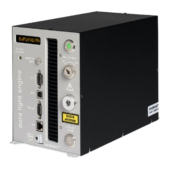
- Page 9 rotor is stopped, all light output channels automatically turn OFF and are locked in this state until the internal temperature is below 50°C and/or the fan restarts. The current reading of the on-board temperature sensor is displayed on the front panel status display (Figure 4, #2) and in the control GUI (Figure 6, #8).
- Page 10 OPERATION AND/OR DAMAGE THE PRODUCT, AND COULD IMPACT SAFETY. Customers planning to connect multiple Light Engine remote interlocks together will need to contact Lumencor prior to integration. INTERCONNECTING LIGHT ENGINES OR USING THE REMOTE INTERLOCK INCORRECTLY CAN RESULT IN ANOMALOUS BEHAVIOR AND/OR DAMAGE TO THE PRODUCTS.
-
Page 11: Operation
Do not press any buttons or insert any plugs during this time. 7. When the initiation sequence completes, “LUMENCOR” will flash on front display panel and then be replaced by a display showing the current light engine IP address, the internal temperature and the fan status. - Page 12 Notes: [1] The light output port incorporates an interlock circuit that disables light output unless a liquid light guide, optical fiber or custom fiber bundle is connected to the output port. Open interlock conditions are indicated by a red (●) ILK indicator in the control GUI (Figure 6, #9) [2] If the DC power supply remained energized after the the previous shut down, press the master power button to start.
- Page 13 Figure 6. Light Engine Control GUI. Control Page (Left) and Settings Page (Right). 1) Lumencor light engine model number and software version. 2) ON/OFF toggle control of source channel (filled circle = ON, ring = OFF). 3) Intensity control slider. 4) Live power read out in mW.
- Page 14 LEGACY command set. A complete listing of STANDARD mode commands is provided in Lumencor Light Engine Command Reference (Document number 57-10018). Note that LEGACY and STANDARD mode communications use different serial protocols (9600,8,N,1 and 115200,8,N,1 respectively).
-
Page 15: Light Output Characteristics
filters associated with each are shown on the Certificate of Conformance (Figure 1) included with the shipping documents e-mailed by Lumencor to the customer. The Figure 7. 9X BNC-terminated breakout cable to certificate of conformance also shows full (100%) power enable TTL triggering (Lumencor p/n 29-10156). - Page 16 [1]. Internal bandpass filters are not user-exchangeable and changes require return of the light engine to Lumencor’s factory for service (see Section 8). Since changing bandpass filters will result in source output power changes, a new certificate of conformance will be provided as part of this service.
-
Page 17: Operational Specifications
Certificates of conformance are also recorded in Lumencor’s database and copies can be requested by e-mail to techsupport@lumencor.com. The request message must include the 4- or 5-digit serial number of the light engine. -
Page 18: Routine Maintenance And Troubleshooting
503-213-4269 or through e-mail at techsupport@lumencor.com. Please be prepared to provide the 4- or 5-digit serial number of the light engine. Any light engine returned to Lumencor for repairs or upgrades requires a pre-issued return material authorization (RMA) number. To request an RMA... -
Page 19: Warranty
fill out and submit the online request form. It is the customer’s responsibility to properly package and safely ship products to Lumencor. Instructions for shipping will be provided in the e-mail giving notification of the RMA number. 9. Warranty The AURA Light Engine is backed by a 24 month warranty to end users.
Need help?
Do you have a question about the AURA N and is the answer not in the manual?
Questions and answers