Table of Contents
Advertisement
Quick Links
MP5 Plus Writer User's Guide
The purpose of this document is to provide instructions on how to use the MP5 Plus Writer to program Sonix MCUs in
online and offline modes. The document demonstrates an example of programming a 32-bit Cortex-M0 MCU and
includes solutions for common errors. The information disclosed in this document is based on MP5 Plus Writer V4.0 and
the software tool, MP5 Plus Writer V1.14.
Date
Revision
24-Jan-2024
WARNING
TIP
NOTE
www.sonix.com.tw
About This Document
1.0
Initial release
Indicates a hazard with a medium or low level of risk that, if not avoided, could result in minor or
moderate injury.
Indicates a tip that may help you solve a problem or save time.
Provides additional information to emphasize or supplement important points of the main text.
Revision History
Description
Convention
1
DTUG-2410
Advertisement
Table of Contents

Subscribe to Our Youtube Channel
Related Manuals for SONIX MP5 Plus Writer


Summary of Contents for SONIX MP5 Plus Writer
- Page 1 About This Document The purpose of this document is to provide instructions on how to use the MP5 Plus Writer to program Sonix MCUs in online and offline modes. The document demonstrates an example of programming a 32-bit Cortex-M0 MCU and includes solutions for common errors.
-
Page 2: Table Of Contents
MCU Product Series MP5 Plus Writer User's Guide Table of Contents Introduction .................................. 5 Hardware ................................6 1.1.1 MP5 Plus Writer ........................... 6 1.1.2 Accessories ............................7 1.1.3 Setup ..............................8 Software ................................11 1.2.1 Download and Installation ........................12 1.2.2... - Page 3 MCU Product Series MP5 Plus Writer User's Guide List of Figures Figure 1–1 MP5 Plus Writer Top View ......................... 6 Figure 1–2 MP5 Plus Writer Rear View ........................6 Figure 1–3 MP5 Plus Writer Side View ........................7 Figure 1–4 Insert Plug-in Transition Board ........................
- Page 4 List of Tables Table 1–1 Transition Board Selection Table ....................... 7 Table 1–2 MP5 Plus Writer UI Components ......................16 Table 2–1 Offline Programming Modes and Result Indications ................33 Table A1 Solutions for Errors in Online Mode ......................44 Table A2 Solutions for Errors in Offline Mode ......................
-
Page 5: Introduction
1.1 Hardware 1.2 Software The MP5 Plus Writer is a writer incorporating updates from the MP-III Writer and the MP PRO Writer to expand programming compatibility by supporting all Sonix MCUs. Complemented by the convenient software tool, the MP5 Plus Writer provides programming flexibility in online mode and standalone functionality in offline mode. -
Page 6: Hardware
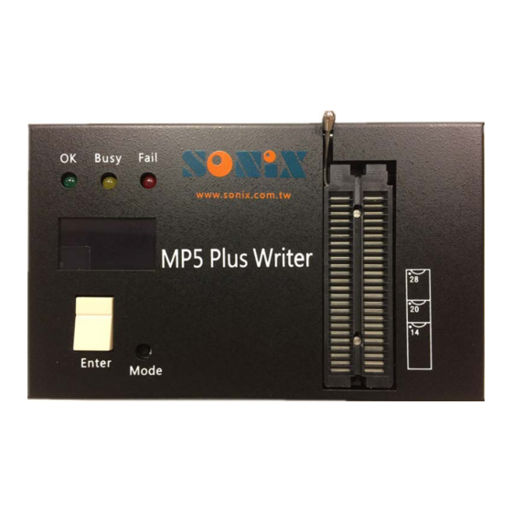
Hardware 1.1.1 MP5 Plus Writer The figures below display the components of the MP5 Plus Writer, and the names are listed and explained below. Figure 1–1 MP5 Plus Writer Top View OK/Busy/Fail light: Each LED light represents a programming status, green for success, yellow for in progress, and red for failure. -
Page 7: Accessories
– – Since the Texttool of the MP5 Plus Writer only holds DIP MCUs, the non-DIP MCUs must be placed in a corresponding socket before connecting to the MP5 Plus Writer via the Texttool. Refer to the socket product list the Sonix official website for an overview of the available options. -
Page 8: Setup
Flip up the lever of the Texttool. Open the cover of the MP5 Plus Writer. Insert J1 and J2 of the plug-in transition board into JP6 and JP6 of the MP5 Plus Writer, respectively. Figure 1–4 Insert Plug-in Transition Board Close the cover of the MP5 Plus Writer. -
Page 9: Figure 1-5 Insert Gold-Finger Transition Board
MCU Product Series MP5 Plus Writer User's Guide STEP 1b Connect the gold-finger transition board to the MP5 Plus Writer. Insert the gold-finger transition board directly into the slot on the side of the MP5 Plus Writer. Proceed to STEP 2. Gold-finger Transition Board Figure 1–5... -
Page 10: Figure 1-7 Socket And Wired Transition Board Connection
Open the cover of the MP5 Plus Writer. Connect one side of the 20-pin ribbon cable to JP5 of the MP5 Plus Writer. Connect the other side of the 20-pin ribbon cable to J2 of the socket board. Make sure the pin 1 of JP5 matches the VDD of J2. -
Page 11: Software
Enter the online mode. Connect the MP5 Plus Writer to a PC or NB with a USB-A to USB-B cable or a USB-A to USB-C cable. Once connected, the Busy light blinks in yellow with a beep sound, and the OLED display shows “USB”. If not, disconnect the USB cable and plug the cable in again. -
Page 12: Download And Installation
MCU Product Series MP5 Plus Writer User's Guide 1.2.1 Download and Installation Follow the steps below to download the setup program from the Sonix official website, https://www.sonix.com.tw/article-en-3980-26454, and install the tool. STEP 1 Locate the compressed installation file. Find the MP5 Writer_Vx.xx .rar in the Attachments section of the MP5 Plus Writer webpage. -
Page 13: Figure 1-12 Setup Wizard
MCU Product Series MP5 Plus Writer User's Guide STEP 5 Proceed the installation. Click Next to start. Figure 1–12 Setup Wizard STEP 6 Accept license agreement. Click I Agree to proceed. Figure 1–13 Accept License Agreement www.sonix.com.tw DTUG-2410... -
Page 14: Figure 1-14 Set Destination Of The Installation
MCU Product Series MP5 Plus Writer User's Guide STEP 7 Choose installation location. Click Install to install the tool in a preassigned destination. Figure 1–14 Set Destination of the Installation STEP 8 Wait for the completion of the tool installation. -
Page 15: Figure 1-16 Complete The Tool Installation
Complete the installation. Click Finish to complete the tool installation. Figure 1–16 Complete the Tool Installation STEP 10 Run the MP5 Plus Writer. Double-click the MP5 Writer Vx.xx.exe in the MP5Writer_Vxxx folder to run the tool. Figure 1–17 Run MP5 Plus Writer www.sonix.com.tw... -
Page 16: User Interface
User Interface I. Main Window The items on the main window of MP5 Plus Writer are categorized into three, action buttons (1 to 9), information display (10 to 16, 20 & 21), and settings (17 to 19). Figure 1–18 MP5 Plus Writer User Interface Table 1–2... -
Page 17: Figure 1-19 Rolling Code Dialog
Verify Mode Setting: Check the box to exclude the rolling code of the address when verifying the programmed data. Security checksum is displayed only when the security of the loaded *.sn8 file is enabled. The encrypt function is supported only in MP5 Plus Writer V1.07 or later versions. www.sonix.com.tw DTUG-2410... -
Page 18: Figure 1-20 Rolling Code Set
MCU Product Series MP5 Plus Writer User's Guide Click OK to complete the settings, and the Rolling Code dialog closes automatically. The Rolling Code button on the main window becomes clickable as framed in Figure 1–20. Click the Rolling Code button to reset the parameters if necessary. -
Page 19: Figure 1-21 Check Pin Assignment Window
MCU Product Series MP5 Plus Writer User's Guide III. Check Pin Assignment Click the Check Pin Information button on the left to inquire the pin assignment, programming pins, and the transition board of the MCU to be programmed. Figure 1–21 Check Pin Assignment Window Select the chip series, chip name, and the package type under the Description. -
Page 20: Figure 1-22 Pin Assignment Window
Double-click the Pin Assignment window to see the programming pin mapping as shown in Figure 1–23. The numbers in the square brackets indicate the pin numbers of JP5 of the MP5 Plus Writer. Double-click the window again to see the transition board as shown in Figure 1–24. -
Page 21: Figure 1-24 Transition Board View
IV. About MP5 Plus Writer Click the exclamation icon on the top of the main window for the About MP5 Plus Writer dialog to pop up. The dialog shows Sonix contact information. Click the Machine Code button at the lower-left corner to copy down the machine code required for the encryption of the programming files. -
Page 22: Figure 1-26 Option Dialog
Keyless mode: Select to enable the automatic detection and programming of the MCU without pressing the Enter key on the MP5 Plus Writer. This selection is available only after loading the ROM code file. Blank check for OTP type MCUs; Erase for flash type MCUs. -
Page 23: Figure 1-27 Sn8/Hex Encrypt Builder Dialog
Click the flash icon on the top of the main window for the SN8/HEX Encrypt Builder dialog to pop up. The components of the dialog are listed and explained below. Figure 1–27 SN8/HEX Encrypt Builder Dialog MP5 ID: Field to enter the machine code of the MP5 Plus Writer. Password: 123456 by default. Limit the number of burn : Field to set the maximum number of programming times (Default: 100). -
Page 24: Figure 1-28 Chip Information Window
MCU Product Series MP5 Plus Writer User's Guide VII. Report Click the R icon on the top of the main window for the chip information window to pop up. The chip information window is only available in the offline mode. -
Page 25: Figure 1-29 Information Of The Rom Code File In Offline Mode
MCU Product Series MP5 Plus Writer User's Guide Figure 1–29 Information of the ROM Code File in Offline Mode www.sonix.com.tw DTUG-2410... -
Page 26: Programming
Proceed to STEP 2 to encrypt the ROM code file prior to programming, or to STEP 3 for programming without encryption. Figure 2–1 MP5 Writer.exe STEP 2 Encrypt. (optional) Click the exclamation icon on the top of the main window for the About MP5 Plus Writer dialog to pop up. www.sonix.com.tw DTUG-2410... -
Page 27: Figure 2-2 About Mp5 Plus Writer Dialog
MCU Product Series MP5 Plus Writer User's Guide Figure 2–2 About MP5 Plus Writer Dialog Click the Machine Code button in the bottom and copy down the machine code. Figure 2–3 Machine Code Click OK to close the About MP5 Writer dialog. -
Page 28: Figure 2-4 Sn8/Hex Encrypt Builder Dialog
MCU Product Series MP5 Plus Writer User's Guide Figure 2–4 SN8/HEX Encrypt Builder Dialog Enter the machine code in the MP5 ID field. Leave the default value, 123456, as the password. Set a maximum number of programming times (optional), or use the default value, 100. -
Page 29: Figure 2-6 Encrypt Builder Dialog
MCU Product Series MP5 Plus Writer User's Guide Figure 2–6 Encrypt Builder Dialog Click OK to close the Encrypt Builder dialog. Close the SN8/HEX Encrypt Builder dialog. An encrypted file (.sn8d/.hexd) is created in the same folder as the .sn8/.hex file as circled in Figure 2–4. -
Page 30: Figure 2-9 Rom Code File Loading Complete
MCU Product Series MP5 Plus Writer User's Guide Figure 2–9 ROM Code File Loading Complete STEP 5 Auto program. Click the Auto Program button to blank check/erase, program the MCU, and verify the programmed data. Wait for the blank checking/erasing, programming, and the verification to complete. -
Page 31: Figure 2-11 Verification Complete
MCU Product Series MP5 Plus Writer User's Guide STEP 6 Verify. (optional) Click the Verify button for the verification of the programmed data in the MCU. The result in the figure below shows the programmed data matches the loaded ROM code file. -
Page 32: Offline
MP5 Plus Writer enters the offline programming mode. The MP5 Plus Writer automatically checks the checksum. If correct, the yellow light blinks once with a beep sound, and the OLED display shows the chip name, the firmware version, and the checksum of the ROM code file. -
Page 33: Table 2-1 Offline Programming Modes And Result Indications
MCU Product Series MP5 Plus Writer User's Guide Table 2–1 Offline Programming Modes and Result Indications Success Fail Mode Function OLED Display LED Light OLED Display LED Light Blank check/Erase + Checksum or FUN0 Green ERR0 to ER40 Program + Verify... -
Page 34: Example-Programming A 32-Bit Cortex-M0 Mcu
MCU Product Series MP5 Plus Writer User's Guide Example—Programming a 32-bit Cortex-M0 MCU 3.1 Preparation 3.2 Programming The example demonstrates how to program SN32F247B, a Sonix 32-bit MCU, with an MP5 Plus Writer in online mode. Preparation 3.1.1 Hardware The hardware requirements for this demonstration include a PC or NB and the parts listed below: Figure 3–1... -
Page 35: Figure 3-2 Insert Transition Board
MP5 Plus Writer User's Guide Follow the steps below to set up the hardware. STEP 1 Connect the plug-in transition board to the MP5 Plus Writer. Flip up the lever of the Texttool. Open the cover of the MP5 Plus Writer. -
Page 36: Software
Connect the socket to the MP5 Plus Writer. Flip the lever of the Texttool down until the lever is 90° to the surface of the MP5 Plus Writer. Place the socket on the Texttool in the direction referring to the pin 1 mark on the cover. -
Page 37: Programming
MCU Product Series MP5 Plus Writer User's Guide Programming After confirming the MP5 Plus Writer is powered on and properly connected to the PC or NB, follow the steps below to program the 32-bit MCU in online mode. STEP 1 Run the MP5 Plus Writer software tool. -
Page 38: Figure 3-7 Machine Code
MCU Product Series MP5 Plus Writer User's Guide Figure 3–7 Machine Code Click OK to close the About MP5 Writer dialog. Click the encrypt icon for the SN8/HEX Encrypt Builder dialog to show. Figure 3–8 SN8/HEX Encrypt Builder Enter the machine code, 23PY6711, in the MP5 ID field. -
Page 39: Figure 3-10 Encrypt Builder Dialog
MCU Product Series MP5 Plus Writer User's Guide Select HEX File (*.hex) in the Files of Type field. Confirm the file to be encrypted, SN32F247B.hex, in the File Name field. Click Open and the Encrypt Builder dialog pops up. Figure 3–10 Encrypt Builder Dialog Click OK to close the Encrypt Builder dialog. -
Page 40: Figure 3-12 Open Rom File Window
MCU Product Series MP5 Plus Writer User's Guide Figure 3–12 Open ROM File Window STEP 4 Load the ROM code file. Select the EncryptHEX_SN32F247B.hexd file created in STEP 2 and click Open to load. Wait for the loading to complete. -
Page 41: Figure 3-14 Set Code Option
MCU Product Series MP5 Plus Writer User's Guide STEP 5 Set code option. The Code Option window pops up after loading the ROM code file. Figure 3–14 Set Code Option Select CS0 for code security and click OK to close the Code Option window. -
Page 42: Figure 3-16 Auto Programming Complete
MCU Product Series MP5 Plus Writer User's Guide STEP 6 Auto program. Click the Auto Program button to erase ROM code of the MCU, program the MCU, and verify the programmed data. Wait for the auto programming to complete. The programming counts are updated upon completion. -
Page 43: Figure 3-18 Reading Complete
MCU Product Series MP5 Plus Writer User's Guide STEP 7 Read the programmed data. Click the Read button to start reading the ROM data. After reading, a .BBB file is saved in the same path as the EncryptHEX_SN32F247B.hexd file. Figure 3–18 Reading Complete www.sonix.com.tw... -
Page 44: Appendix A - Troubleshooting
Fail light on in red and a beeping sound. Press the Enter key once to turn off the red light and the sound. Table A2 explains each error code in offline mode and provides the corresponding solutions. Contact a Sonix representative or a distributor for assistance if the error still exists after applying all possible methods. -
Page 45: Table A2 Solutions For Errors In Offline Mode
Solutions Confirm the power adapter is connected and powered on. ERR0 Programming voltage fail Remove the MCU and power on the MP5 Plus Writer again. Remove the MCU. ERR1 Blank check fail Confirm the MCU is blank. -
Page 46: Appendix B - Test Mode
Appendix B – Test Mode Follow the steps below to measure the programming voltages, VXX and VPP, of the MP5 Plus Writer in test mode. The USB cable must remain disconnected from the PC or NB for the MP5 Plus Writer to enter the test mode. - Page 47 Unintended Use of Sonix products is solely at the user’s own risk and without recourse to Sonix or any of its suppliers, agents or representatives in connection therewith. The information contained in this document is the property of Sonix, and none of it may be used, reproduced or distributed without the express written permission by Sonix.
- Page 48 MCU Product Series MP5 Plus Writer User's Guide Sonix Technology Co., Ltd. Headquarter Taipei Office 10F-1, No. 36, Taiyuan Street, 15F-2, No. 171, Songde Road, Zhubei City, Hsinchu County, Taiwan Xinyi District, Taipei City, Taiwan Tel: +886-3-5600-888 Tel: +886-2-2759-1980 Fax: +886-3-5600-889 Fax: +886-2-2759-8180 http://www.sonix.com.tw/masterpage-en...
Need help?
Do you have a question about the MP5 Plus Writer and is the answer not in the manual?
Questions and answers