Table of Contents
Advertisement
Quick Links
Dual-Channel Arbitrary
Waveform Generator
User Manual
AG1012F
AG1022F
AG2052F
AG2062F
For product support, visit:www.owon.com.hk/download
※:The illustrations, interface, icons and characters in the user manual may be slightly
different from the actual product. Please refer to the actual product.
Advertisement
Table of Contents

Subscribe to Our Youtube Channel
Related Manuals for Owon AG1012F


Summary of Contents for Owon AG1012F
- Page 1 Waveform Generator User Manual AG1012F AG1022F AG2052F AG2062F For product support, visit:www.owon.com.hk/download ※:The illustrations, interface, icons and characters in the user manual may be slightly different from the actual product. Please refer to the actual product.
- Page 2 LILLIPUT Company. Fujian LILLIPUT Optoelectronics Technology Co., Ltd. No. 19, Heming Road Lantian Industrial Zone, Zhangzhou 363005 P.R. China Tel: +86-596-2130430 Fax: +86-596-2109272 Web: www.owon.com.cn E-mail: info@owon.com.cn...
- Page 3 General Warranty We warrant that the product will be free from defects in materials and workmanship for a period of 3 years from the date of purchase of the product by the original purchaser from our company. This warranty only applies to the original purchaser and is not transferable to a third party.
-
Page 4: Table Of Contents
Table of Contents 1. General Safety Requirements ................1 2. Safety Terms and Symbols ..................2 3. General Characteristics ..................3 4. Quick Start ......................4 Front/Rear Panel and User Interface ................5 Front Panel ...............................5 Rear Panel ............................... 6 User Interface ............................7 General Inspection ...................... - Page 5 FM (Frequency Modulation) ........................ 28 PM (Phase Modulation) ........................29 PWM (Pulse Width Modulation) ......................30 FSK (Frequency Shift Keying) ......................31 ASK (Amplitude Shift Keying) ......................33 PSK (Phase Shift Keying) ........................34 To Generate Sweep ....................... 35 To Generate Burst ......................36 Set the N-Cycle Burst ...........................37 Set the Gated Burst ..........................
-
Page 6: General Safety Requirements
1.General Safety Requirements 1. General Safety Requirements Before any operations, please read the following safety precautions to avoid any possible bodily injury and prevent this product or any other products connected from damage. In order to avoid any contingent danger, this product is only used within the range specified. -
Page 7: Safety Terms And Symbols
2.Safety Terms and Symbols 2. Safety Terms and Symbols Safety Terms Terms in this Manual. The following terms may appear in this manual: Warning: Warning indicates the conditions or practices that could result in injury or loss of life. Caution: Caution indicates the conditions or practices that could result in damage to this product or other property. -
Page 8: General Characteristics
3.General Characteristics 3. General Characteristics The product is dual-channel multi-function generator which combines Arbitrary Waveform Generation and Function Generation. The product introduces Direct Digital Synthesizer (DDS) technology to provide stable, precise, pure and low distortion signal. The user-friendly interface design and panel layout bring exceptional user experience. -
Page 9: Quick Start
4.Quick Start 4. Quick Start This chapter will deal with the following topics mainly: Front/Rear Panel Overview User Interface Overview How to Implement General Inspection How to Adjust the Foot Stools How to Implement Power-On Check... -
Page 10: Front/Rear Panel And User Interface
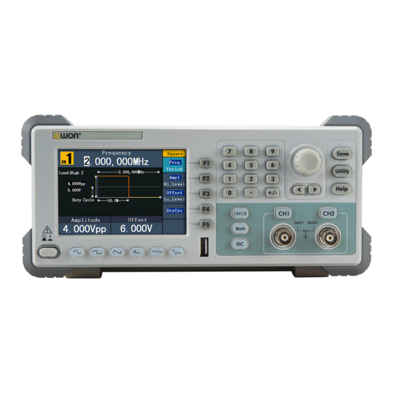
4.Quick Start Front/Rear Panel and User Interface Front Panel Figure 4- 1 Front panel overview ① LCD Display the user interface. ② Menu selection Include 5 buttons: F1 - F5, activate the corresponding buttons menu. ③ Number keys Input parameters, include: number, point and plus/minus sign. -
Page 11: Rear Panel
4.Quick Start Control lighted when CH2 is tuned on. ⑩ CH2 Output Output signal of CH2.(When "Sync" is turned on, it is the synchronization output signal end) ⑪ Foot stool Make the instrument to be tilted for ease of operation ⑫... -
Page 12: User Interface
4.Quick Start ① Power socket AC input connector ② Fuse The rating is 100 - 120 V 250 V, F1AL 220 - 240 V 250 V, F0.5AL ③ Power switch Switch between 110 V and 220 V. ④ USB (type B) This can be used to connect a USB type B controller. -
Page 13: General Inspection
4.Quick Start ① Current channel. ② Parameter 1, display parameter and edit the focused parameter. ③ Current signal type or mode. ④ The setting menu of current signal or mode. ⑤ Parameter 3, display parameter and edit the focused parameter. ⑥... -
Page 14: Foot Stool Adjustment
4.Quick Start Foot Stool Adjustment Unfold the foot stools on the bottom of the generator, as shown in the following figure. Power-On Check AC Power Input Setting Adopt 100 - 120 VAC or 220 - 240 VAC power source. Users should regulate the voltage scale of the Power Switch according to the standards in their own country (see Figure 4- 2) at the rear panel. -
Page 15: Power On
4.Quick Start Power On (1) Connect the instrument to the AC supply using the supplied power cord. Warning: To avoid electric shock, the instrument must be grounded properly. (2) Press down the power button at the front panel, the screen shows the boot screen. -
Page 16: Front Panel Operation
5.Front Panel Operation 5. Front Panel Operation This chapter will deal with the following topics mainly: How to Set Channels How to Output Sine Signals How to Output Square Signals How to Output Ramp Signals How to Output Pulse Signals ... -
Page 17: To Set Channels
5.Front Panel Operation To set channels To Switch Channels for Display Press CH1/2 button to switch channel displayed on the screen between CH1 and CH2. To Display/Edit Both Channels Press Both button to display the parameters of both channels. To switch channel: Press CH1/2 to switch the editable channel. -
Page 18: To Set Signals
5.Front Panel Operation (2) Press to select From CH2 To CH1, or press to select From CH1 To CH2. To set signals The following describes how to set and output Sine, Square, Ramp, Pulse, Noise, Arbitrary, DC signals and copy channel. To Output Sine Signals Press button to call the user interface of Sine signal, the Sine waveform... -
Page 19: To Set The Start Phase
5.Front Panel Operation Figure 5- 3: Set the frequency using number keys To Set the Start phase F2 , the "Start phase" menu item is highlighted.In Parameter 1, a cursor Press appears under the value of start phase. Use the knob or the number keys to set the desired value. - Page 20 5.Front Panel Operation menu selection buttons on the right. To set the Frequency/Period, Start phase,Amplitude/High Level, Offset/Low Level, please refer to To Output Sine Signals on page 13. Press button to enter the NextPage interface,then press button to select TTL Output, TTL level will be outputted. When the load is High Z, the output signal is set to 5Vpp amplitude and 2.5V offset.
-
Page 21: To Set The Duty Cycle
5.Front Panel Operation To Set the Duty Cycle (1) Press F5 button to enter the NextPage interface,then press F1 button to select the "DtyCyc" menu item is highlighted, the current value of the Duty cycle is displayed in Parameter 1. (2) Turn the knob to change the value directly;or press the number keys to input the desired value, press F4 to choose "%". -
Page 22: To Set The Symmetry
5.Front Panel Operation Figure 5- 6: The User Interface of Ramp Signal Term Explanation Symmetry: The percentage that the Rising Period takes up the whole Period. To Set the Symmetry (1) Press button, the "Symmetry" menu item is highlighted, the current value of the symmetry is displayed in Parameter 1. -
Page 23: To Set The Pulse Width / Duty Cycle
5.Front Panel Operation parameters can be set by operating the Pulse setting menu on the right. The parameters of Pulse waveform are: Freq/Period,Start phase, Ampl/Hi_Level, Offset/Lo_Level, P_Width/DtyCyc. You can operate the menu by using the menu selection buttons on the right. To set the Frequency/Period,Start phase, Amplitude/High Level, Offset/Low Level, please refer to To Output Sine Signals on page 13. -
Page 24: To Output Noise Signals
5.Front Panel Operation Figure 5- 9: Set the Pulse Width of Pulse signal To Output Noise Signals The noise signal which the generator output is white noise. Press button to call the user interface of Noise signal, the Noise waveform parameters can be set by operating the Noise setting menu on the right. -
Page 25: To Select The Built-In Waveform
5.Front Panel Operation menu items of Arbitrary waveform are: Freq/Period,Start phase, Ampl/Hi_Level, Offset/Lo_Level, Built-in Wform, Editable Wform. You can operate the menu by using the menu selection buttons on the right. To set the Frequency/Period,Start phase, Amplitude/High Level, Offset/Low Level, please refer to To Output Sine Signals on page 13. - Page 26 5.Front Panel Operation press F1 to enter the Built-in Wform menu. (2) Press F1 to select Common, Maths, Window or Others. E.g. select Maths to enter the following interface. (3) Turn the knob or press direction key to choose the desired waveform. E.g.
-
Page 27: The User-Definable Waveform
5.Front Panel Operation Square function HaverSine HaverSine function Lorentz Lorentz function Natural logarithm function Cubic Cubic function Cauchy Cauchy distribution Besselj Bessel I function Bessely Bessel II function Error function Airy Airy function Windows Rectangle Rectangle window Gauss Gauss distribution Hamming Hamming window Hann... -
Page 28: To Output Dc
5.Front Panel Operation turn the knob or press the number keys to input the desired value and choose the unit. X1, XK, XM respectively represent 1, 1000, 1000,000. The waveform points range is 2 - 1000,000. (3) Set the interpolation: Press to switch between On/Off. -
Page 29: To Recall Wave File
5.Front Panel Operation (2) Press button, then press F4 to enter the Built-in Wform menu. (3) Press F4 to select Others. Select DC. Press F1 to output DC. F4 , confirm whether the "Offset" menu item is highlighted; if not, (4) Press to switch into "Offset". -
Page 30: Use Waveform Generators To Recall Wave
5.Front Panel Operation Figure 5- 13: Cut Wave Use waveform generators to recall wave: (1) Enter the operation menu: Press →Editable Wform →Select Wform. Enter the following interface: Figure 5- 14: Choose storage device (2) Select USBDEVICE, select Next Level. Turn the knob or press direction key to select the saved example.ota waveform file. - Page 31 2. The max data number of AG1012F AG1022F ARB is 8192. When the wave cut from oscilloscope contains data number more than 8192, AG1012F and AG1022F will compress data.
-
Page 32: To Generate The Modulated Waveform
5.Front Panel Operation To Generate the Modulated Waveform Modulation function is only used for CH1. Press the Mod button, then press to select Mod to generate modulated waveform. The waveform generator can modulate waveform using AM, FM, PM, PWM, FSK, ASK, and PSK. To turn off the modulation, press the Mod button. -
Page 33: Fm (Frequency Modulation)
5.Front Panel Operation Noise or Arb . (6) Press to set AM Freq. The range is 2 mHz - 20 kHz (Internal source only). (7) Press F4 to set Mod Depth. The range is 0% - 100%. Term Explanation AM Frequency: The frequency of modulating waveform. -
Page 34: Pm (Phase Modulation)
5.Front Panel Operation Signals on page 13. Press button again to return to the Modulation mode interface. (4) Press F5 to select the source. If the source is External, use the Ext Mod In connector in the rear panel to input the external signal, then skip ahead to step (7). -
Page 35: Pwm (Pulse Width Modulation)
5.Front Panel Operation (1) Press Mod function button, then press F1 to select Mod. (2) Press to switch Mod Type to PM. If the Carrier Waveform is not Sine, the system will switch it to Sine automatically. (3) Press button to display the waveform and parameters of the Carrier Waveform. -
Page 36: Fsk (Frequency Shift Keying)
5.Front Panel Operation How to set the parameters of PWM (1) Press Mod function button, then press F1 to select Mod. (2) Press F1 to switch Mod Type to PWM. If the Carrier Waveform is not Pulse, the system will switch it to Pulse automatically. (3) Press button to display the waveform and parameters of the Carrier Waveform. - Page 37 5.Front Panel Operation Figure 5- 21: The User Interface of FSK How to set the parameters of FSK (1) Press Mod function button, then press F1 to select Mod. (2) Press to switch Mod Type to FSK. If the Carrier Waveform is not Sine, the system will switch it to Sine automatically.
-
Page 38: Ask (Amplitude Shift Keying)
5.Front Panel Operation Term Explanation FSK Rate: The frequency at which the output frequency shifts between the carrier frequency and the Hop frequency (Internal Modulation only). ASK (Amplitude Shift Keying) Amplitude Shift Keying modulation is a modulation technique that shifts the output signal amplitude between two amplitudes: the carrier amplitude and modulating amplitude. -
Page 39: Psk (Phase Shift Keying)
5.Front Panel Operation set to Negative. (6) Press to set Ampl. Carrier waveform amplitude shifts to the modulating amplitude with the specified ASK rate, and then returns to the original amplitude. Term Explanation ASK Rate: The rate at which the output amplitude shifts between the carrier amplitude and the modulating amplitude is called the ASK rate (Internal Modulation only). -
Page 40: To Generate Sweep
5.Front Panel Operation Negative. The external source can be offered by the Ext Trig/Burst/Fsk In connector in the rear panel. Set the Slope to Positive and the generator would output the carrier phase when the external input signal is logic low level and output the modulating phase when the external input signal is logic high level. -
Page 41: To Generate Burst
5.Front Panel Operation instance, press to display the waveform and parameters. You can change the parameters, please refer to To set signals on page 13. Press button again to return to the Sweep mode interface. (3) Press to set Sweep Time, the Time Span of the Sweep for which the Frequency changes from the Start Frequency to Stop Frequency. -
Page 42: Set The N-Cycle Burst
5.Front Panel Operation Set the N-Cycle Burst Figure 5- 25: The User Interface of N-Cycle Burst (1) When the output signal is Sine, Square, Ramp, Pulse or Arbitrary waveform, press the Mod button, then press F3 to select Burst. (2) Press button to choose the waveform. -
Page 43: Set The Gated Burst
5.Front Panel Operation Set the Gated Burst Figure 5- 25: The User Interface of Gated Burst (1) When the output signal is Sine, Square, Ramp, Pulse or Arbitrary waveform, press the Mod button, then press F3 to select Burst. (2) Press button to choose the waveforms. -
Page 44: To Edit The File Name
5.Front Panel Operation desired storage. Press to enter the chosen storage. Provide operations as Next level, Up one level, New folder, Delete, Rename, Copy, Paste. (3) Remove the USB device: Remove the USB device from the USB port on the front panel. -
Page 45: To Set The Separator
5.Front Panel Operation percent, press F4 to select the unit. The bright range is 0% - 100%. To Set the Separator The user can set the separator of the displayed parameter. (1) Press Utility and choose Disp Setup, press F2 to select Sepr. (2) Press F2 to switch between Comma, Space, Off, Dot. -
Page 46: To Set Output Parameter
5.Front Panel Operation For low amplitude signal, the “Middle” or “High” sensitivity should be used. For low frequency signal with high amplitude and slower rising edge, low sensitivity is a better choice. To set the high frequency restrain on/off: Press F3 to switch HFR as ON/OFF. -
Page 47: To Set Sync
5.Front Panel Operation To Set Sync (1) Press Utility and choose Output Setup, press F4 to select Sync. (2) Press F4 to switch between On/Off. (3) If On is selected, button light is on; press again to disable the synchronous output, and the output level of the CH2 output is logic low. Note: When the amplitude is relatively low, disabling Sync Signal can reduce the distortion in output. -
Page 48: To Set The System
5.Front Panel Operation zero intersections). To Set the System Language Setting Press Utility and choose System, press F1 to switch display languages. Power On Setting (1) Press Utility and choose System, press F2 to select Power On. (2) Press to switch between Default/Last. Default means that all the settings return to default when powered. -
Page 49: To Set The Beep
5.Front Panel Operation PWM deviation 0.0% FSK Hop Frequency 100.000 0 Hz FSK Rate 100.000 0 Hz ASK Rate 100.000 0 Hz PSK Rate 100.000 0 Hz Source Internal Sweep Default Start/Stop Frequency 100.000 0 Hz/1.000 000 kHz Time 1 sec Mode Linear Burst... -
Page 50: To Set The Clock Source
5.Front Panel Operation To Set the Clock Source The waveform generator provides an internal clock source and also accepts external clock source input from the [Ref Clk/Counter In] connector at the rear panel. It can also output a clock source from the [Ref Clk Out] connector for other device to use. -
Page 51: Communication With Pc
USB driver. The driver is in the "USBDRV" folder under the directory where the ultrawave communication software is installed, such as "C:\Program Files\OWON\ultrawave\USBDRV". (3) Port setting of the software: Run the ultrawave software; click "Communications" in the menu bar, choose "Ports-Settings", in the setting dialog, choose "Connect using"... -
Page 52: Scpi
7.SCPI 7. SCPI The waveform generator supports SCPI, and the users can operate and control the device by USB port. For the detailed information about SCPI, please refer to AG Series Waveform Generator SCPI Protocol. 8. Troubleshooting 1. The instrument is powered on but no Display. ... -
Page 53: Technical Specifications
Arbitrary Waveforms Staircase, etc. 45 built-in waveforms, User-Definable Waveform Numbers of channel Frequency Characteristic Frequency resolution: 1 μHz AG1012F,AG1022F Max sampling rate 125 MSa/s, AG2052F ,AG2062F Max sampling rate 300 MSa/s Sine AG1012F 1 μHz—10 MHz AG1022F 1 μHz—25 MHz AG2052F 1 μHz—50 MHz... - Page 54 1 mV Accuracy Output 50 Ω (typical) Impedance Waveform Characteristic Sine AG1012F 1 μHz to 10 MHz:0.2 dB AG1022F 10 MHz to 25 MHz:0.3 dB Flatness (when the Amplitude is 1.0 V (+4 dBm), relative to 1 μHz to 10 MHz:0.2 dB...
- Page 55 9.Technical Specifications AG1012F 1 ns + 30 ppm AG1022F Jitter (rms) AG2052F 300 ps + 100 ppm of period AG2062F Non-symmetry (below 50% 1% of period+ 5 ns Duty Cycle) Overshoot < 5% AG1012F 20% - 80% (< 1 MHz)
- Page 56 9.Technical Specifications Modulated Waveform Carrier Waveforms Sine Source Internal/ External Internal Modulating Waveforms Sine,Square,Ramp, White Noise, Arbitrary Internal AM Frequency 2 mHz - 20 kHz Depth 0.0% - 100.0% Carrier Waveforms Sine Source Internal/ External Internal Modulating Waveforms Sine,Square, Ramp,White Noise, Arbitrary Internal Modulating Frequency 2 mHz - 20 kHz Frequency Deviation...
- Page 57 9.Technical Specifications Sweep Time 1 ms to 500 s ± 0.1% Source Source, External or Manual Burst Waveforms Sine, Square, Ramp, Pulse, Arbitrary Types Count (1 to 50,000 periods), infinite, gated Start Phase -360° - +360° Internal Period (10 ms - 500 s) ± 1% Gated Source External Trigger Trigger Sources...
- Page 58 9.Technical Specifications Trigger Delay 0.0 ns - 60 s External Reference Clock Input Impedance 1 kΩ, AC coupled Requested Input voltage swing 100 mV to 5 V Locking range 10 MHz ± 9 kHz Counter Input (share the same port as External Reference Clock Input) DC offset range ±1.5 VDC 250 mV...
- Page 59 9.Technical Specifications Relative Humidity ≤ 90% Operating: 3,000 m Height Non-operating: 15,000 m Cooling Method Fan cooling Mechanical Specifications Dimension 235 mm × 110 mm × 295 mm (W*H*D) Weight 3 kg Interval Period of Adjustment: One year is recommended for the calibration interval period.
-
Page 60: Appendix
10.Appendix 10. Appendix Appendix A: Enclosure A power cord that fits the standard of the destination country A USB cable A CD (PC link application software) A Quick Guide A BNC/Q9 cable Appendix B: General Care and Cleaning General Care Do not store or leave the instrument where the liquid crystal display will be exposed to direct sunlight for long periods of time.
Need help?
Do you have a question about the AG1012F and is the answer not in the manual?
Questions and answers