Advertisement
Quick Links
Machine Translated by Google
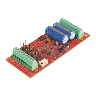
#36125 PIKO SmartDecoder 4.1 G
locomotive decoder for large
railways multiprotocol
SmartDecoder 4.1
Description
This PIKO SmartDecoder 4.1 G is a compact, very powerful multi-protocol decoder. It can be used in DCC, Motorola® and mfx® digital systems and also runs in analogue operation with direct or
alternating voltage.
The respective operating mode is recognized automatically, but it can also be set manually. The load-controlled decoder works with a motor frequency of 18.75 kHz and is therefore suitable not only
for DC but also for bell-armature motors (e.g. Faulhaber, Maxon, Escap) up to to a continuous current consumption of 5 A. Short-term higher motor currents are well tolerated. Thanks to its large
energy storage, the decoder is ideal for use in garden railway vehicles, as it can buffer dirty rail sections very well.
The PIKO SmartDecoder 4.1 G is RailCom® and RailCom Plus® capable and can handle both ABC braking and ABC slow travel. The motor characteristic curve is set using the minimum, average
and maximum speed (simple characteristic curve), or via the extended characteristic curve with individual settings for 28 speed levels.
The decoder has two direction-dependent lighting outputs, as well as eleven additional special function outputs, three of which are equipped with logic levels.
It also offers four connections for standard model building servos. Decoder-internal processes can be called up automatically via the three inputs for reed contacts, for example. The maneuvering
gear with an extended slow travel range and the three possible acceleration and braking delays can be switched using function keys.
Features •
Suitable for DC and bell-armature motors up to 5 A • Quiet motor
running thanks to motor control at 18.75 kHz • 14, 27, 28, 128
speed levels, depending on data format • Short
(1-127) and long (128-9999) addresses • NMRA
compliant •
RailCom® and RailCom Plus® •
mfx®
capable • Energy storage with adjustable start-up and supply time •
Minimum, maximum and average speed adjustable • Extended
speed characteristic curve adjustable •
Additional starting characteristic curve can be activated for smooth starting
• Shunting gear (half speed) can be switched • 3
adjustable acceleration and braking delays, each switchable via F0 - F28 • Direction-
dependent light outputs, dimmable • 11 function outputs
(3x logic), A1 -A7 dimmable, direction dependence adjustable • 4 servo outputs, two stopping
positions each and speed adjustable • 3 inputs for reed contacts or Hall sensors
for Triggering decoder-internal processes • Activation of the light and function outputs for
analogue operation, adjustable • Second dimming for lighting, A1 to A7 adjustable,
switchable • Simple function mapping, F0 - F12 for lighting, A1 to A7,
acceleration, braking delay and maneuvering gear • Extended Function mapping,
F0 - F44 for switching several outputs
depending on linked conditions • The function keys F1 -F44 can be assigned directly to
the outputs A8 -A11 • Train-side lighting
can be switched off
Installation and connection of the PIKO SmartDecoder 4.1 G
You can attach the decoder to a suitable location in your vehicle using the appropriate screws. When installing, ensure that you do not pinch or damage any cables
with the screw heads. When placing the module in the vehicle, make sure that there is no conductive connection anywhere. Connect the decoder as described in
Figure 1. Only use suitable cable material with a sufficient cross-section for cabling. When using the screw terminals, make sure the screwdriver is the right size
so that the screw terminals are not damaged. The assignment of the respective connections can be found in the following figures. The first commissioning should
take place on the programming track with the control center in programming mode. When reading or programming, very small currents usually flow that do not
damage the decoder in the event of a short circuit.
Special functions A1 to A11
The special function outputs A1 to A8 of the decoder are designed as a row of screw terminals on the right side of the decoder. The second connection for these
consumers is labeled U+ in the same terminal row in Figure 1.
engine
M
Rear
light
Wheelset
Figure 1: Connection of motor, front and rear lighting, wheelset
A11 logic output
A10 logic output
A9 logic output
3.3 volts
Figure 3: Connection pads on the back
ATTENTION: Soldering on the decoder and connecting electronic circuits should only be carried out by experienced specialists with the appropriate knowledge and appropriate tools. The warranty
does not apply to decoders that have been damaged due to improper handling.
A short circuit in the area of the motor, lighting, grinder and wheelsets destroys the module and
Input 3
red
Engine 1
blue
Engine 2
brown
Light H
Light V
Light
yellow black
U+
in front
Input 1
GND
white
Wheel left.
Gray
Wheel right.
Input 2
A11 A10 A9
3.3V
possibly the electronics of the locomotive!
• Function outputs: flashing with variable on/off time • Function
outputs: 2 phases for alternating flashers • Load-
dependent smoke generator control • Firebox
with setting parameters for brightness changes and flickering rhythm • Shunting clutch
and shunting tango • Showing and
hiding the light and function outputs, adjustable • Energy-saving lamp
effect: achieving the maximum Brightness after an adjustable time • Fluorescent lamp
switch-on effect with adjustable flash time and number • 8 PWM banks, each
with 64 modulation entries for e.g. North American lighting effects such as Mars Light, Gyra Light,
Strobe, etc. • With SUSI socket for
corresponding PIKO sound modules and function decoders • Braking with DCC
Braking signal, braking distances with DC voltage or ABC brakes • ABC slow travel distance •
2 adjustable braking
distances in cm, can be activated via ABC, DC, DCC brake signal, as well as via speed level
0 with adjustable speed level threshold • 2 motor control
types for precise motor control with many setting parameters • Motorola with 3
addresses for the functions F1 - F12 when used with Motorola control panels • All outputs
protected against short circuits • Error memory
for motor and function outputs, as well as temperature shutdown • Conventional direct
and alternating current operation with automatic switching to the respective operating mode •
All CVs have digital devices
DCC and Motorola formats • Programmable in DCC mode via register, CV direct or page
programming • Main track programming (DCC) • Decoder programming lock
SUSI
U+
Aux 1
Aux 2
Servo 1 GND
Aux 3
Aux 4
Servo 2
GND
Aux 5
Aux 6
Servo 3
GND
Aux 7
Aux 8
Servo 4
GND
Connection of the function outputs
The terminals U+ and GND (-) required for connecting the logic outputs A9 - A11 are located on the screw
terminal row on the front of the decoder.
The soldering pad marked 3.3V is used to connect a Hall sensor, which is connected as shown in Figure 2.
3.3V soldering pad back
Hall sensor
e.g. TLE4906L
Inputs 1, 2, 3
Reed contact
GND
Figure 2: Connection of reed contact or Hall sensor
Advertisement

Related Manuals for PIKO 36125


Summary of Contents for PIKO 36125
- Page 1 SmartDecoder 4.1 Description This PIKO SmartDecoder 4.1 G is a compact, very powerful multi-protocol decoder. It can be used in DCC, Motorola® and mfx® digital systems and also runs in analogue operation with direct or alternating voltage. The respective operating mode is recognized automatically, but it can also be set manually. The load-controlled decoder works with a motor frequency of 18.75 kHz and is therefore suitable not only for DC but also for bell-armature motors (e.g.
- Page 2 Commissioning the decoder (delivery status) Enter address 3 on the control unit. Depending on which data format it was addressed with, the PIKO SmartDecoder 4.1 G runs in DCC mode with 28 speed levels or in Motorola mode. When using a RailCom Plus®- capable digital control center or an mfx®-capable digital control center, the decoder logs on automatically and can be operated immediately.
- Page 3 Machine Translated by Google RailCom Plus® switched on via bit 7. If RailCom Plus® is switched on, the decoder automatically logs on to a RailCom Plus® capable control center (e.g. PIKO SmartControl) with its locomotive symbol, decoder name and its special function symbols. Thanks to this RailCom Plus® technology, no locomotive data has to be stored in the control center and no locomotive addresses have to be programmed into the decoder.
- Page 4 Machine Translated by Google Example 1: The rear light output should only be switched using the F5 function key. The CV to be programmed is CV39 for the function key F5. The value 2 (rear light output) is programmed into this CV39. So that the rear light output is no longer switched backwards in the direction of travel via the function button F0, the CV34 must also be programmed to the value 0 for the function button F0 in the direction of travel backwards.
- Page 5 Machine Translated by Google Softly show and hide light and function outputs If the output is switched on or off, it will fade in or out smoothly. In CV186 you can specify which output should receive this blending function. CV 186: Value Value Bit 4 A4 with blend function 16...
- Page 6 Servo control On the PIKO SmartDecoder 4.1 G, up to four servos can be operated on the corresponding pin strips (see Figure 1). Please pay attention to the correct polarity when connecting the servo connectors. As a rule, the darkest cable of a commercial model building servo (usually black) is the GND cable. As can be seen in Figure 1, this must point in the direction of the adjacent row of clamps.
- Page 7 CV180 has expired. This holding time results from the value of CV 180 multiplied by 100ms. To make programming easier, especially for modulating the PWM output, we recommend using the testing and programming device PIKO SmartProgrammer (# 56415) and PIKO SmartTester (#56416).
- Page 8 CV169 must therefore be programmed with the value 81 for servo 2. To make programming easier, especially for extended function mapping, we recommend that you use the testing and programming device PIKO SmartProgrammer (# 56415) and PIKO SmartTester (#56416). Second dimming of the light and function outputs (CV96 = 1) The light and function outputs can be set to an alternative, i.e.
-
Page 9: Resetting To Factory Settings (Reset)
The configuration variables (CVs) form the basis of all setting options for the decoder. The decoder can be programmed with the digital control centers PIKO SmartControl, PIKO SmartControl Light, or other DCC control centers, as well as with Motorola control centers. - Page 10 Machine Translated by Google Programming with Mobile Station 1, 2 & 3 Mobile Station 1: The programming menu is only available in the locomotive menu for certain locomotives. A locomotive that has a programmable decoder must be selected from the database. Proceed as follows: 1.
- Page 11 Machine Translated by Google Area Value* Description 0-255 Simple function mapping Assignment of the function outputs to the CVs of the function keys F0 - F12 CV 33 Light function button (F0) when driving forward CV 34 Light function button (F0) when reversing CV 35 function key F1 CV 36 Function key F2 CV 37 Function key F3...
- Page 12 Machine Translated by Google Area Value* Description 0-255 Forward speed correction Extended speed level characteristic for speed levels 1 - 28 0-255 each different. 0-255 Reverse speed correction 0, 1 Type of function mapping 0 = simple function mapping, 1 = extended function mapping 97 ABC brakes 0-255 Voltage difference for diode path is approx.
- Page 13 Machine Translated by Google Area Value* Description 0-255 144 Start-up delay 2 (as a replacement for CV3) 0-255 145 Braking delay 2, (as a replacement for CV4) 0-255 146 Start-up delay 3 (as a replacement for CV3) 0-255 147 Braking delay 3, (as a replacement for CV4) 0-28 148 Function key number for ABV 2 (255=off) 0-28...
- Page 14 Machine Translated by Google CV table for programming banks 1 - 4 Bank 1, extended function mapping, lines 1 - 16 (CV31=8,CV32=0), factory values range 257-272 Condition ON: 144, 0, 0, 0, 0, 0, Condition OFF: 0, 0, 0, 0, 0, 0, Output: 0, 1, 0, 0, 0 - 255 each 273-288 Condition ON: 16, 0, 0, 0, 0, 0, Condition OFF: 128, 0, 0, 0, 0, 0, Output: 0, 2, 0, 0, 0 - 255 each 289-304 Condition ON: 1, 0, 0, 0, 0, 0, Condition OFF: 0, 0, 0, 0, 0, 0, Output: 1, 0, 0, 0,...
- Page 15 Please note that, according to EMC law, the module may only be operated in vehicles that have the CE mark carry. Subject to changes and printing errors. As of 09/19. Copying and copying only with the permission of the publisher. PIKO Spielwaren GmbH Lutherstr. 30 96515 Sonneberg 36125-90-7100_2019...
Need help?
Do you have a question about the 36125 and is the answer not in the manual?
Questions and answers