
Related Manuals for Automatic Systems BL 229


Summary of Contents for Automatic Systems BL 229
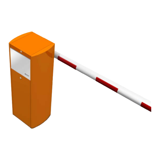
- Page 1 BL 229 Automatic rising barrier Technical manual Rev.D • Update 06/2022 BL 229 BL 229 Toll For more information, please visit www.devancocanada.com or call toll free at 855-931-3334...
-
Page 3: Table Of Contents
Balancing table for BL 229 Toll (For information only) ....... . - Page 4 Fig. 40 - Dimensions of BL 229 with articulated arm....... .
-
Page 5: Safety Warnings
This equipment is designed to control and manage vehicle access and cannot be applied to any other use without risk to users or to the integrity of the equipment. Automatic Systems cannot be held responsible for damage caused by improper use of the equipment. - Page 6 BL 229 This symbol is used to highlight information that may help you to better understand the product. This symbol is used to highlight an important instruction for the correct use and/or maintenance of the product. ATTENTION! This symbol is used to indicate a risk of injury or property damage.
-
Page 7: Presentation
2. PRESENTATION There are currently two BL 229 models: The first model, which we will call 'BL 229': • for a wide range of applications; • equipped with a round arm for free passage from 10' [3.05m] to 19'8'' [6m];... -
Page 8: Description
BL 229 3. DESCRIPTION 3.1. COMPONENT LOCATION REP. DESCRIPTION Housing Lockable cover Front panel Lockable door Raised base (optional) Arm fastening clamp Bearing Arm shaft Connecting rod lever Fig. 1 - Component location - General Spring lever Balance spring Spring anchor plate... -
Page 9: Operation Principle
The breakaway device, which comes as standard with toll model and is available as an option for the BL 229 Standard, allows the arm to pivot (the arm comes out of its fastening jaw) when an impact occurs. The breakaway device reduces damage to the barrier and the vehicle hitting it. -
Page 10: Location Of Labels And Documents
Inside of the door. following documents: • Technical manual Dossier Technique Électrique Electrical Technical File Schaltplan • Electrical diagram • Implementation drawing • Option documents BL 229 BL 229 Toll BL 229 BL 229 Toll Rev. 00 • Update 07/2021 www.automatic-systems.com... - Page 11 BL 229 REP. REPRESENTATION DESCRIPTION LOCATION Label with QR Code giving access to the On the top plate of the housing technical documentation of the product (inside the gate). digitally (web). Product identification label. On the top plate of the housing (inside the gate).
-
Page 12: Installation
BL 229 4. INSTALLATION On receipt, check the state of the material. Immediately notify your insurance company or your distributor if any damage occurred during transport. If necessary, proceed with the repairs. ATTENTION! SAFETY INSTRUCTIONS! 1. The installation personnel must follow all local regulations and standards applicable to the gate installation site. -
Page 13: Preparing The Base Plate
BL 229 4.1. PREPARING THE BASE PLATE The barrier cannot be installed directly on the ground, you can choose between: - A concrete base plate, by means of the fixing frame provided when requested (detailed procedure hereafter); - Or on a raised base (provided as an option);... -
Page 14: Placing The Equipment
BL 229 4.2. PLACING THE EQUIPMENT • Bring the equipment on site by means of an appropriated handling device (hand truck or equivalent). • Remove the cardboard packaging. • Unlock and remove the side door (5). The keys are attached on the arm’s fixing clamp (7). - Page 15 BL 229 • If needed, add adjustment shims under the housing to obtain the correct levelling of the barrier. Only tighten the nuts (36) after the arm ( Chap. 4.4, page 17) and the optional tip support are installed. ( Chap. 4.5, page 21) ATTENTION! THE FOLLOWING PROCEDURE MUST BE PERFORMED PRIOR TO OPERATING YOUR GATE.
-
Page 16: Conversion From One Solution To Another
BL 229 4.3. CONVERSION FROM ONE SOLUTION TO ANOTHER The barrier can be configured in 4 different ways, according to the position of the arm with regard to the door and the road. To change from one configuration (solution) to another, the mechanism must be adapted: the arm is either on the door side (solution 2+3) or opposite to the door side (solution 1+4), and the motor turns in one direction (solution 1+2) or the other one (solution 3+4). - Page 17 BL 229 Table of operations to be carried out, marked , to move from one solution to another: 1 2 1 3 1 4 2 3 2 4 3 4 ...
- Page 18 BL 229 1 2 1 3 1 4 2 3 2 4 3 4 Insert the shaft into the bearings by passing it through the two correctly positioned levers: they must be directed respectively towards the...
-
Page 19: Installation Of The Arm
BL 229 4.4. INSTALLATION OF THE ARM 4.4.1. INSTALLATION OF A ROUND ARM BL 229: standard equipment. BL 229 Toll: unavailable. M 12 x 40 DIN 933 M 12 DIN 127 M 12 DIN 125 Fig. 17 - Installation of a round arm •... -
Page 20: Installation Of A Round Arm With Breakaway Device
BL 229 4.4.2. INSTALLATION OF A ROUND ARM WITH BREAKAWAY DEVICE BL 229: available in option. BL 229 Toll: unavailable. Fig. 18 - Installation of a round arm with breakaway device • Jaw (8) in vertical position, remove screws (1) and the lock washers (2), the flat washers (3) the rod threaded at its ends (4) and the spacers (5) of the jaw. -
Page 21: Installation Of An Oval Arm With Breakaway Device
BL 229 4.4.3. INSTALLATION OF AN OVAL ARM WITH BREAKAWAY DEVICE BL 229 Toll: standard equipment. BL 229: available in option. Fig. 19 - Installation of an oval arm with breakaway device • Jaw (8) in vertical position, remove the screw (1), the washer (2), the nut (3), the spacers (4) and the sleeve (5) of the jaw. -
Page 22: Installation Of A Protecta ® Arm With Breakaway Device
® BL 229: available in option. BL 229 Toll: available in option. Fig. 20 - Installation of a Protecta® arm with breakaway device • Jaw (7) in vertical position, remove screw (1), lock washer (2), flat washer (3), the rod threaded at its ends (4) and the spacers (5) of the jaw. -
Page 23: Installation Of The Tip Support
BL 229 4.5. INSTALLATION OF THE TIP SUPPORT BL 229: availablein option. BL 229 Toll: unavailable. The tip support is automatically provided with any barrier that is longer than 16'5'' [5m] and is optionally available for shorter arms. The tip support’s role is to maintain the end of the arm in its horizontal position and to ensure its rigidity. -
Page 24: Electrical Connections
BL 229 4.6. ELECTRICAL CONNECTIONS DO NOT CONNECT TO A FLOATING NETWORK OR TO HIGH IMPEDANCE EARTHED INDUSTRIAL DISTRIBUTION NETWORK. HIGH LEAKAGE CURRENT. IMPERATIVELY CONNECT TO THE GROUND WITH A 14 AWG CABLE MINIMUM BEFORE CONNECTING THE MAINS. DO NOT CONNECT MORE THAN 1 GATE TO THE SAME DIFFERENTIAL BREAKER. -
Page 25: Adjustments
BL 229 5. ADJUSTMENTS 5.1. POSITIONING THE LEVERS ON THE ARM SHAFT The connecting rod and spring levers ( Rep.10 and 11, Chap. 3.1, page 6) must be positioned on the arm shaft ( Rep.9, Chap. 3.1, page 6) according to the chosen solution. -
Page 26: Balancing Of The Arm By Means Of The Spring
BL 229 5.2. BALANCING OF THE ARM BY MEANS OF THE SPRING The tension of the spring must be adjusted in such a way as to ensure minimal effort for the motor both at the opening and the closing of the barrier: 1. -
Page 27: Balancing Table For Bl 229 (For Information Only)
BL 229 5.3. BALANCING TABLE FOR BL 229 (FOR INFORMATION ONLY) POSITION Ø OF NB OF LENGTH ARM TYPE OPTION SPRING SPRINGS SPRINGS WIRE ON LEVER Round Ø 81 Round Ø 81 1 arm light kit Round Ø 81 2 arm light kits Round Ø... -
Page 28: Balancing Table For Bl 229 Toll (For Information Only)
BL 229 5.4. BALANCING TABLE FOR BL 229 TOLL (FOR INFORMATION ONLY) POSITION Ø OF NB OF LENGTH ARM TYPE OPTION SPRING SPRINGS SPRINGS WIRE ON LEVER Oval arm Protecta ® Spring position on lever: mark: (5) Fig. 25, page 24. -
Page 29: Levelling Of The Arm
BL 229 5.5. LEVELLING OF THE ARM 1. First check the position of the levers on the arm shaft ( Fig. 23, page 23). 2. Close the barrier so the arm is in its horizontal position. 3. On the connecting rod ( Rep. 19, Chap. 3.1, page 6), loosen nuts (1) and (2). -
Page 30: Limit Switch Settings
BL 229 5.6. LIMIT SWITCH SETTINGS The limit switches are usually installed in the factory according to the customer requested solution and will not require any adjustment. The limit switch comes standard with the standard BL229 with arm length between 10' [3.05 m] and 16'5'' [5 m]. -
Page 31: Analog Sensor Settings
BL 229 5.7. ANALOG SENSOR SETTINGS The analog sensor and cam are usually installed in the factory according to the customer requested solution and will not require any adjustement. The analog sensor comes standard with the BL229 Toll and with standard BL229 with arm of 18' [5.5m] or longer. - Page 32 BL 229 Arm in open position Fig. 32 - Gate mechanism in open position Mounting screws Spiral cam Analog sensor Fig. 33 - Detail of mounting screws fixing the spiral cam...
-
Page 33: Calibration Of The Analog Sensor
BL 229 5.8. CALIBRATION OF THE ANALOG SENSOR THE GATE WILL NOW MOVE TO DETERMINE THE UP AND DOWN POSITION! 1. Place the gate arm in the closed position; 2. Disconnect the RJ45 connector of the frequency converter to prevent gate arm from moving. -
Page 34: Configuring The Frequency Converter
The factory settings allow the frequency drive and gear motor to be protected against all malfunctions. These values should therefore not be changed under any circumstances. ANY CHANGES TO THESE PARAMETERS WITHOUT HAVING THE EXPRESS PERMISSION OF AUTOMATIC SYSTEMS WILL VOID THE PRODUCT WARRANTY The frequency converter is a Schneider Altivar ATV12 connected in Modbus. -
Page 35: Use
BL 229 6. USE 6.1. COMMISSIONING Before commissioning, review the procedures described in chapters 4. Installation, 5. Adjustments, 6. Use and 6.3. Maintenance. The following list can be used as a checklist for commissioning the barrier. F Anchor the gate to the base in accordance with the recommendations of the ( Ch. 4. Installation, page 10). -
Page 36: Manual Opening In The Event Of Power Failure
BL 229 6.2. MANUAL OPENING IN THE EVENT OF POWER FAILURE 6.2.1. PROCEDURE FOR SOLUTION 1 OR 2 The BL229 barriers are available in 4 solutions depending on the position of the arm and the door in relation to the road (... -
Page 37: Procedure For A Solution 3 Or 4
• Check if the frequency converter ( Rep. 25, Fig. 1, page 6) is in fault: the red LED on the side of the converter blinks. In this case, contact an Automatic Systems representative. • Check the connection of the commands according to the electrical diagram provided with the equipment. - Page 38 BL 229 When you decommission the equipment, empty the oil from the gear motor ( Rep. 18, page 6) and scrap the various components of the machine by the appropriate means (metal parts, electronic components, etc) according to your local...
-
Page 39: Dimensions
2 1/2 � [64mm] : J �{�t*���s���r. � � ;�4 NOTE elevation to prevent the Fig. 38 - Dimensions of BL 229 with round arm water accu mu lotion at base of the MA TË RIAU/MATERIA L DIMENSIONS I FORMAT... -
Page 40: Dimensions Of Bl 229 With Articulated Arm (Option)
- - - - - - - - - - - - - - - - - - CONCRETE BASE MATËRIAU/MATERIAL LES DIMENSIONS SONT EN Fig. 40 - Dimensions of BL 229 with articulated arm. POUCES / DIMENSIONS ARE IN INCHES TRAITEMENT /TREATMENT 1 IULtl<ANCtS... -
Page 41: Appendix
BL 229 8. APPENDIX • Electrical drawings : can be found in the document pocket ( Chap. 3.5, page 8). • Implementation drawings: NAM-BL229-IN-01-EN and NAM-BL229-IN-02-EN. • Preventive maintenance guide: NAM-BL229-PM-EN. • AS1620 Control Unit handbook. HOW TO ORDER REPAIR PARTS...
Need help?
Do you have a question about the BL 229 and is the answer not in the manual?
Questions and answers