Table of Contents

Related Manuals for Lumistar LS-27-M


Summary of Contents for Lumistar LS-27-M
- Page 1 LS-27-M User’s Manual 03/17/2024 LS-27-M Modular RF Downconverter/Receiver User’s Manual Lumistar Inc. 3186 Lionshead Ave. Suite 100 Carlsbad, California 92010 (760) 431-2181 www.lumistar.net Lumistar Inc. DOC-LS-27-M-01-USM-02...
- Page 2 Lumistar, Inc. This document is provided as is, with no warranties of any kind. Lumistar, Inc. disclaims and excludes all other warranties and product liability, expressed or implied, including but not limited to any implied...
-
Page 3: Table Of Contents
.................... 21 ESKTOP CHASSIS ABLING NTERFACES ....................... 26 HASSIS PTIONS 3.5.1 ..........................26 ESKTOP HASSIS 3.5.2 1U 12” LS-27-M C ........................29 HASSIS ................... 30 OOLING AND HERMAL ONDITIONING COMMUNICATIONS AND PROGRAMMING INTERFACE ..............31 /USB I ....................... 31 ERIAL NTERFACE ..................... - Page 4 PPLICATION PERATIONS 5.3.1 LS-27-M S .......................... 50 ETUP 5.3.1.1 LS-27-M Setup Tab – Status Area ....................51 5.3.1.2 LS-27-M Setup Tab – Channel 1 and 2 Controls ................. 52 5.3.2 ..........................56 ONFIGURE 5.3.3 ........................... 58 YSTEM ALUES Lumistar Inc.
- Page 5 Figure 2-4 Block Diagram: Slice 4 – Processing, and DC Power Conversion ............12 Figure 3-1 Representative Top View of the LS-27-M brick assembly ................. 15 Figure 3-2 Representative Top View of the LS-27-M brick assembly mounted on optional Mounting Plate ..........................................16 Figure 3-3 Representative front View of the LS-27-M brick assembly mounted on optional Mounting Plate ..........................................
- Page 6 Figure 5-2 Device Manager Ports – Expanded (Example) ....................49 Figure 5-3 IP Address Changer Application .......................... 50 Figure 5-4 LumistarDevice – LS-27-M Setup Tab ........................ 51 Figure 5-4 LumistarDevice – Configure Tab .......................... 57 Figure 5-4 LumistarDevice – System Values Tab ......................... 59 List of Tables Table 2-1 General LS-27-M Device Specifications Table ....................
- Page 7 LS-27-M User’s Manual 03/17/2024 Acronyms AGC - Automatic Gain Control AM - Amplitude Modulation BNC - Bayonet Neill–Concelman (connector) BSC – Best Source Combining BW – Bandwdith dB – Decibel dBm – Decibel milliwatts DHCP – Dynamic Host Configuration Protocol...
-
Page 8: Introduction
Consult the web site for the most recent release of all related product documentation. 1.2 Document Outline This document contains the following sections: Section 1 provides a document overview as well as a brief on the LS-27-M design ▪ Section 2 provides receiver theory of operation ▪... -
Page 9: List Of Referenced Documents
LS-27-M User’s Manual 03/17/2024 Figure 1-1 Document Flag Formats 1.3 List of Referenced Documents Several documents were referenced in the making of this document. A list of these documents includes: Telemetry Standards: (IRIG-106-2015) ▪ User Datagram Protocol (RFC 768) ▪... -
Page 10: Theory Of Operation
Future additions include second IF Automatic Frequency Control (AFC). Some of the primary design objectives of the LS-27-M product line were to reduce the platform size, to provide an “OS-less” environment by eliminating product use of commercial software operating systems for functional processing, to provide easy and flexible field upgrade/enhancements capabilities, and to provide a network appliance for device control and data transport. -
Page 11: Figure 2-1 Block Diagram: Slice 1 - Rf To If Downconversion
LS-27-M User’s Manual 03/17/2024 Figure 2-1 Block Diagram: Slice 1 - RF to IF Downconversion Figure 2-2 Block Diagram: Slice 2 - 2 IF and Analog Processing Lumistar Inc. DOC-LS-27-M-01-USM-02... -
Page 12: Figure 2-3 Block Diagram: Slice 3 - Fm Video Discrimination And Processing
LS-27-M User’s Manual 03/17/2024 Figure 2-3 Block Diagram: Slice 3 – FM Video Discrimination and Processing Figure 2-4 Block Diagram: Slice 4 – Processing, and DC Power Conversion Lumistar Inc. DOC-LS-27-M-01-USM-02... -
Page 13: Table 2-1 General Ls-27-M Device Specifications Table
(2) MicroDSub-15 Plug Power/Digital I/O Connector (1) MicroDSub-25 Receptacle/Plug Environmental Temperature, Operational -20° to 70° Celsius Temperature, Storage -40° to 85° Celsius <40° C 10-90%, >40° C 0-75% Humidity, non-condensing Table 2-1 General LS-27-M Device Specifications Table Lumistar Inc. DOC-LS-27-M-01-USM-02... -
Page 14: Table 2-2 Desktop Rackmount Chassis - Device Specifications Table
Total Power (both Channels) ~ 30 Watts Performance All Receiver Performance Parameters (Same as that of the LS-27-M shown in Error! Reference s ource not found.) DC Power Supply Desktop mount in. (mm.) 8.20 (208) x 2.90 (73) x 1.6 (39) -
Page 15: Hardware Specifications, Cabling And Operations
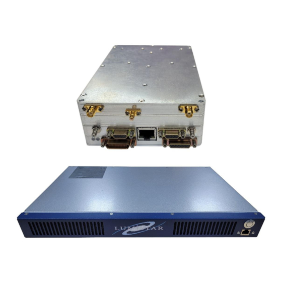
3.1 Mechanical Outline – Basic Receiver The LS-27-M is described as a “brick” configuration having the same traditional footprint as a standard 3.5” host computer hard disk drive. Figure 3-1 provides a diagram of the top view of the device. Figure 3-2 illustrates that unit mounted on an optional mounting plate. -
Page 16: Figure 3-2 Representative Top View Of The Ls-27-M Brick Assembly Mounted On Optional Mounting Plate
LS-27-M User’s Manual 03/17/2024 Figure 3-2 Representative Top View of the LS-27-M brick assembly mounted on optional Mounting Plate Figure 3-3 Representative front View of the LS-27-M brick assembly mounted on optional Mounting Plate Lumistar Inc. DOC-LS-27-M-01-USM-02... -
Page 17: Figure 3-4 Front-Views Of The Ls-27-M Brick Assembly
LS-27-M User’s Manual 03/17/2024 Figure 3-4 Front-Views of the LS-27-M brick assembly Lumistar Inc. DOC-LS-27-M-01-USM-02... -
Page 18: Interface Signals: Micro-D Sub Pin-Outs
The LS-27-M contains either one or two multi-color status LEDs on the front of the device. These are shown in Figure 3-3 and referenced as D1 and D2. The LEDs provide high-level functional status to the user and can be used in physical location of a particular device in the case that multiple devices have been deployed. -
Page 19: Figure 3-5 Revision 2 Cable: Ls-27-M J4 And J5 Connector Pin-Out Details
LS-27-M User’s Manual 03/17/2024 Figure 3-5 Revision 2 Cable: LS-27-M J4 and J5 Connector Pin-out Details Figure 3-6 Revision 2 Cable: LS-27-M J11 and J12 Connector Pin-out Details Lumistar Inc. DOC-LS-27-M-01-USM-02... -
Page 20: Interface Signals: Electrical Definitions/Characteristics
LS-27-M User’s Manual 03/17/2024 3.3 Interface Signals: Electrical Definitions/Characteristics The interface signals of the LS-27-M vary in type and electrical complexity. There are several different types of signals deployed as detailed in Table 3-1. Signal Name Interface Interface Input Input... -
Page 21: Desktop Chassis Cabling Interfaces
03/17/2024 3.4 Desktop chassis Cabling Interfaces The LS-27-M in the Desktop chassis assembly is typically delivered with a set of four interface cables. These cables interface connections on the Micro D-Sub connections to more commonly available interface connections such as BNC, USB-B, DSub9 and HD15 connections. -
Page 22: Figure 3-7 P4 User Interface Cable
LS-27-M User’s Manual 03/17/2024 Figure 3-7 P4 User Interface Cable Lumistar Inc. DOC-LS-27-M-01-USM-02... -
Page 23: Figure 3-8 P5 User Interface Cable
LS-27-M User’s Manual 03/17/2024 Figure 3-8 P5 User Interface Cable Lumistar Inc. DOC-LS-27-M-01-USM-02... -
Page 24: Figure 3-9 P11 User Interface Cable
LS-27-M User’s Manual 03/17/2024 Figure 3-9 P11 User Interface Cable Lumistar Inc. DOC-LS-27-M-01-USM-02... -
Page 25: Figure 3-10 P12 User Interface Cable
LS-27-M User’s Manual 03/17/2024 Figure 3-10 P12 User Interface Cable Lumistar Inc. DOC-LS-27-M-01-USM-02... -
Page 26: Chassis/Case Options
Lumistar offers an optional LS-27-M desktop chassis that provides mounting, power cabling provisions, and cooling functions for the LS-27-M. The fixture comes with a desktop AC to DC power converter. This unit is shown in Figure 3-11. The fixture can be operated on input voltages between 9 and 36VDC. In addition, fixtures can be stacked and mounted together as shown in Figure 3-12. -
Page 27: Figure 3-12 Ls-27-M Desktop Chassis - Stacked Iso View
LS-27-M User’s Manual 03/17/2024 Figure 3-12 LS-27-M Desktop chassis – Stacked ISO view Figure 3-13 LS-27-M Desktop chassis – Envelope Dimensions Lumistar Inc. DOC-LS-27-M-01-USM-02... -
Page 28: Figure 3-14 Ls-27-M Desktop Chassis - Lower Housing Mounting Points
LS-27-M User’s Manual 03/17/2024 Figure 3-14 LS-27-M Desktop chassis – Lower Housing Mounting Points Lumistar Inc. DOC-LS-27-M-01-USM-02... -
Page 29: 12" Ls-27-M Chassis
LS-27-M User’s Manual 03/17/2024 3.5.2 1U 12” LS-27-M Chassis Lumistar offers the LS-27-M designs in 19” 1U rackmount configuration. Figure 3-15 LS-27-M 1U 12” Chassis Front and Rear Panels Lumistar Inc. DOC-LS-27-M-01-USM-02... -
Page 30: Cooling And Thermal Conditioning
LS-27-M User’s Manual 03/17/2024 The 12” deep 1U LS-27-M chassis requires an external host PC to run the application software to control and status the LS-27-M. The chassis contains the receiver and all power and cooling provisions. The chassis also contains an unmanaged 100/10Mbps Ethernet 5-Port Switch (model: Netgear GS305-100PAS) for network connections between the internal receiver and the front and rear panel mounted Ethernet connectors. -
Page 31: Communications And Programming Interface
The LS-27-M provides a USB 2.0 serial interface. Included with the delivery is a driver installation that converts the USB serial interface into a standard MS Windows or Linux COM port for simplifying the interface. -
Page 32: Initial Setup Of The Network Interface For The Ls-28-Drsm
The LS-27-M supports the traditional protocol of all existing LS-27-B product families as well as “extended” LS-27-M series commands. By default, the LS27 protocol is backwards compatible with all previous generations of the LS-27-B products. The LS-27-M series of commands will be additions to the existing set of LS-27-B commands. -
Page 33: Figure 4-1 Message Header - Ls-27 Protocol
LS-27-M User’s Manual 03/17/2024 All host messages require a message header of six (6) bytes. If the host command requires additional data be transferred to the host, the data will immediately follow the command header. Figure 4-1 contains a diagram of the message header for the interface protocol. -
Page 34: Ping Command Messaging - 0X0000 Message Id
LS-27-M User’s Manual 03/17/2024 Figure 4-2 Message Transaction Examples – LS27 Protocol 4.3.1.1.1 Ping Command Messaging – 0x0000 Message ID The “Ping” command is used to determine the health and presence of the communications channel between the host and the receiver. In response to the “Ping” command, the receiver will echo the received message header back to the host only if the responding device identifies as the device ID being requested. -
Page 35: Primary Setup Command/Response Message - 0X1000 Message Id
LS-27-M User’s Manual 03/17/2024 Figure 4-3 Ping Message Construction 0x0000 – LS-27 Protocol 4.3.1.1.2 Primary Setup Command/Response Message – 0x1000 Message ID The “Primary Setup” message provides fundamental control information to the receiver channel. The message header is followed by eight (8) data bytes as defined in Figure 4-4. Bit definitions are also defined below. -
Page 36: Secondary Setup Command/Response Message - 0X1001 Message Id
LS-27-M User’s Manual 03/17/2024 Command Description/Definition Logic State/Explanation Mnemonic Radio Selection Number 0=Radio 1 or Down Converter 1, 1=Radio 2 or Down Converter 2 Automatic Frequency Control 0 =Disabled, 1 = Enabled (Future LS27M Option) INTREF Internal/External Reference Clock Selection... -
Page 37: Figure 4-7 Secondary Setup Message Mode Command Definitions - Ls-27 Protocol
LS-27-M User’s Manual 03/17/2024 Figure 4-7 Secondary Setup Message Mode Command Definitions – LS-27 Protocol Lumistar Inc. DOC-LS-27-M-01-USM-02... -
Page 38: Figure 4-8 Secondary Setup Message Mode Command Responses - Ls-27 Protocol
LS-27-M User’s Manual 03/17/2024 Figure 4-8 Secondary Setup Message Mode Command Responses – LS-27 Protocol Figure 4-9 Secondary Setup Message Mode Command Get Setup Info Responses – LS-27 Protocol Lumistar Inc. DOC-LS-27-M-01-USM-02... -
Page 39: Downconverter Setup Command/Response Message - 0X1100 Message Id
This “extended” firmware command provides all the commanding offered by the 0x1000 command with some expansions of controls added to the LS-27-M second generation of the LS-27 product line. Many of these controls do not apply to the LS-27-B hardware platform. This command can be used in place of the 0x1000 command. -
Page 40: Downconverter Auxiliary Setup Command/Response Message - 0X1101 Message Id
LS-27-B command set. This command, in conjunction with the 0x1100 command, provide most critical commanding of the LS-27-M platform. Many of the functions of this command do not apply to the original LS-27-B generation of hardware. The message structure is shown in Figure 4-12. Content definition of the command is provided in Figure 4-11. -
Page 41: General Status Command/Response Message - 0X2000 Message Id
LS-27-M User’s Manual 03/17/2024 Figure 4-13 Downconverter Auxiliary Setup Message Content Definitions 0x1101 – LS-27 Protocol 4.3.1.1.6 General Status Command/Response Message – 0x2000 Message ID The General Status command provides receiver operational status such as signal strength, deviation amounts, AM index values, and certain lock states. The message definition is shown in Figure 4-14. Bit definitions for the command are shown in Figure 4-15. -
Page 42: Eeprom Page Read Command/Response Message - 0X2009 Message Id
LS-27-M User’s Manual 03/17/2024 Figure 4-16 System Values Status Command 0x2002 – LS-27 Protocol 4.3.1.1.8 EEPROM Page Read Command/Response Message – 0x2009 Message ID The primary receiver configuration information, used to drive software GUIs and controls, is found in the first page (indexed from 0) of the receivers primary internal EEPROM. -
Page 43: Figure 4-17 Eeprom Page Read Message Construction 0X2009- Ls-27 Protocol
LS-27-M User’s Manual 03/17/2024 Figure 4-17 EEPROM Page Read Message Construction 0x2009– LS-27 Protocol Figure 4-18 EEPROM Page Read Message Bit Definitions – LS-27 Protocol Lumistar Inc. DOC-LS-27-M-01-USM-02... -
Page 44: Figure 4-19 Eeprom Page Read Of Primary
LS-27-M User’s Manual 03/17/2024 Figure 4-19 EEPROM Page Read of Primary Page 0 Lumistar Inc. DOC-LS-27-M-01-USM-02... -
Page 45: Current Downconverter Setup Command/Response Message - 0X4100 Message Id
LS-27-M User’s Manual 03/17/2024 4.3.1.1.9 Current Downconverter Setup Command/Response Message – 0x4100 Message ID The Current Downconverter Setup command provides the user software with the present setup state of the receiver. This command reflects the present set of setup information sent by the 0x1100 and/or 0x1000 commands. -
Page 46: Figure 4-21 Current Downconverter Auxiliary Setup Message Construction 0X4101 - Ls-27 Protocol
LS-27-M User’s Manual 03/17/2024 Figure 4-21 Current Downconverter Auxiliary Setup Message Construction 0x4101 – LS-27 Protocol Lumistar Inc. DOC-LS-27-M-01-USM-02... -
Page 47: Application Software Information
03/17/2024 5 Application Software Information Lumistar provides a user application that is capable of control and status for the LS-27-M regardless of its physical configuration. The application is referred to as LumistarDevice. The application is somewhat generic and supports a number of Lumistar product platforms, including the LS-27-B and LS-27-M. The application can communicate over Serial (RS232 or RS422 4-Wire, and USB) or Ethernet interfaces. -
Page 48: Usb 2.0 Interface
LS-27-M User’s Manual 03/17/2024 Figure 5-1 Serial COM Port Connection Window 5.2.2 USB 2.0 Interface To utilize the USB interface to the LS-27 platform, the use of a USB-to-COM port driver is required. This driver is supplied in the “Utilities” folder of the support DVD in the “Prolific USB Driver Installation”. Run the PL23XX-M_LogoDriver_Setup_v400_20211229.exe on the target Windows host machine to install the USB... -
Page 49: 100Mbps Ethernet Interface
Figure 5-2 Device Manager Ports – Expanded (Example) 5.2.3 100Mbps Ethernet Interface The LS-27-M devices will be delivered with a default static IP address of 192.168.1.27 and a subnet mask set to 255.255.255.0. If the user network does not allow for this address, launch the IP_AddressChanger application. -
Page 50: Lumistardevice Application Operations
This section provides LumistarDevice application operations information. 5.3.1 LS-27-M Setup Tab The LS-27-M Setup is the main operational tab of the LumistarDevice application. Once the connection window closes, the user will be presented with an operational window similar to Figure 5-4. -
Page 51: Ls-27-M Setup Tab - Status Area
LS-27-M User’s Manual 03/17/2024 Figure 5-4 LumistarDevice – LS-27-M Setup Tab 5.3.1.1 LS-27-M Setup Tab – Status Area The LumistarDevice application Setup Tab contains an area at the top of the display window that provides the user with receiver status. Each of the statuses are discussed further in the paragraphs within this section. -
Page 52: Ls-27-M Setup Tab - Channel 1 And 2 Controls
RSSI values from both channels. Files will be stored by device Serial number. 5.3.1.2 LS-27-M Setup Tab – Channel 1 and 2 Controls The LumistarDevice application Setup Tab contains a left- and right-hand channel control panels. Controls within these two areas are identical between channels. - Page 53 Tune Frequency: The tune frequency for the receiver channel can be entered in this window. The minimal tune step for the LS-27-M is 1kHz and the minimal tuning step for the LS-27-B is 50kHz. RF Bands Installed Status: This area of the receiver control panel contains status on the RF band filters installed in the receiver channel.
- Page 54 AM Output Impedance Select: This control allows the user to select the output impedance of the AM output. Options of 50 ohms and 75 ohms are available. This option is only available in the LS-27-M configuration. AM HW AGC Time Constant Enable: This option applies a hardware integrator in the output of the AM signal.
- Page 55 AFC On/Off Select: Automatic Frequency Control is processing applied to the IF output. This functionality is a future addition to the LS-27-M. Read Setup 0x4100: This button retrieves the current settings of the upper controls panel.
-
Page 56: Configure Tab
32. Each step represents an approximate 0.5dBm level control. This option is only available in the LS-27-M configuration. Video Gain Adjust: This gain adjustment control is only functional if the FM demodulator is present. This control allows for Video output adjustment using values between 0 and 16383. -
Page 57: Figure 5-4 Lumistardevice - Configure Tab
User Note Entry Window: To simplify unit network identification, especially where multiple LS-27-Ms are present on a network, a 16-character network name tag can be stored in non-volatile memory inside the LS-27-M. This identification tag will be displayed for all LS-27-M devices that can be identified on a given network when launching the LumistarDevice application. -
Page 58: System Values Tab
It should be noted that simply storing the setups internally via the LS-27-M Setup tab will not make the settings recover at power up. Selecting this button will make that action active at boot time. -
Page 59: Figure 5-4 Lumistardevice - System Values Tab
LS-27-M User’s Manual 03/17/2024 Figure 5-6 LumistarDevice – System Values Tab Lumistar Inc. DOC-LS-27-M-01-USM-02...
Need help?
Do you have a question about the LS-27-M and is the answer not in the manual?
Questions and answers