Table of Contents
Advertisement
Quick Links
Advertisement
Table of Contents

Related Manuals for Donnergy GT400TL


Summary of Contents for Donnergy GT400TL
- Page 1 Single-phase Microinverter USER MANUAL Model: GT400TL / GT600TL / GT800TL...
- Page 2 PV module. This setup is highly flexible and reliable as the system enables direct control of the production of each PV module. About the Manual This manual contains important instructions for GT400TL/GT600TL/GT800TL microinverters and users shall read in its entirety before installing or commissioning the equipment. For safety reasons, only...
-
Page 3: Table Of Contents
CONTENTS 1. Important Notes 1.1 Product Range 1.2 Target Group 1.3 Symbols Used 1.4 Radio Interference Statement 2. About Safety 2.1 Important Safety Instructions 2.2 Explanation of Symbols 3. About Product 3.1 About PV Microinverter System 3.2 About Microinverter 3.3 About 2-in-1 Unit 3.4 Highlights 3.5 Terminals Introduction 3.6 Dimensions (mm) - Page 4 13. Frequently Asked Questions...
-
Page 5: Important Notes
Important Notes 1.1 Product Range This manual describes the assembly, installation, commissioning, maintenance and troubleshooting of the following models of Microinverter: · GT400TL · GT600TL · GT800TL *Note: “400” means 400W, “600” means 600 W, “800” means 800 W. 1.2 Target Group This manual is only for qualified technicians. -
Page 6: About Safety
2 . About Safety 2.1 Important Safety Instruction The GT400TL/GT600TL/GT800TL microinverter is designed and tested according to international safety requirements. However, certain safety precautions must be taken when installing and operating this inverter. The installer must read and follow all instructions, cautions and warnings in this installation manual. -
Page 7: Explanation Of Symbols
2.2 Explanation of Symbols Symbol Usage Treatment To comply with European Directive 2002/96/EC on Waste Electrical and Electron- ic Equipment and its implementation as national law, electrical equipment that has reached the end of its life must be collected separately and returned to an approved recycling facility. -
Page 8: About Product
3 . About Product 3.1 About PV Inverter System A typical grid-tied PV inverter system includes PV modules, PV inverter, meter and power grid, as shown below. PV inverter converts the DC power generated by PV modules into AC power that meets the require- ments of the power grid. -
Page 9: About 2-In-1 Unit
3.3 About 2 - in- 1 Unit Microinverters can be divided into 1-in-1, 2-in-1etc., depending on how many PV modules are connected to them. This means that the microinverter can connect to one module and two modules modules respectively, as shown below. This manual is about 2-in-1 microinverter with the output power up to 800 VA. -
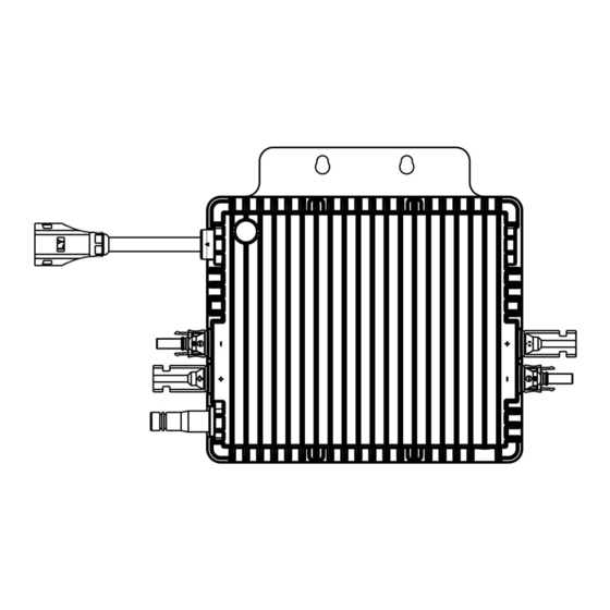
Page 10: Terminals Introduction
3.5 Terminals Introduction Object Description Antenna DC Connector AC Sub Connector 3.6 Dimensions (mm) -
Page 11: Installation Preparation
Installation Preparation 4.1 Position and Space Required Please install the microinverter and all DC connections under the PV module or on the balcony wall to avoid direct sunlight, rain exposure, snow buildup, UV etc. The flat side of the microinverter should be up and facing the PV module or balcony wall. -
Page 12: Installation Tools
Safety shoes 4.4 AC Branch Circuit Capacity GT400TL/GT600TL/GT800TL can be used with 12AWG AC Trunk Cable and the AC Trunk Connector. The number of micro-inverters on each 12AWG AC branch shall not exceed the limit as shown below. Maximum Over current... -
Page 13: Precautions
4.5 Precautions The equipment is installed based on the system design and the location of installation. • The installation must be done with the equipment disconnected from the grid (power disconnect switch open) and with the PV modules shaded or isolated. •... - Page 14 Description Remark Microinverter Include M6X14 Expansion screw*2 Include User Manual Include Protective plug Optional withdrawal tool Optional Microinverter Main Connection cable-800mm 2.5 Optional ㎟ (12AWG) T-shaped Connector BC05C-T 300V/40A Optional BC05A+Euro/Korea general standard plug L- Optional 800mm 3*1.5㎟ BC05A+Euro/Korea general standard plug L- Optional 800mm 3*1.5㎟...
-
Page 15: Microinverter Installation
Microinverter Installation 5 . 1 Accessories Description AC Trunk Cable, 12 AWG Cable M6 × 10 screws (Prepared by the installer) AC Trunk Connector * Note: All accessories above are not included in the package and should be purchased separately. 5 . - Page 16 Note: 1 . Microinverter installation and DC connections must be done to avoid direct sunlight, rain exposure, snow buildup, UV etc. 2 . Leave a minimum of 2 cm of space around the microinverter enclosure to ensure ventilation and heat dissi- pation.
- Page 17 Step 3 . Complete the AC Connection A ) Plug the AC Sub Connector of the microinverter into the AC Trunk click Connector until you hear the click. B ) Connect the AC end cable to the distribution box, and wire it to the local grid network. C ) Please plug the AC Trunk Port Cap click in any vacant AC Trunk Port to...
-
Page 18: Troubleshooting
6 . Troubleshooting 6 . 1 Troubleshooting List Handling suggestions Alarm status 1. Check the ventilation and ambient temperature at the microinverter installation location. 2. If the ventilation is poor or the ambient temperature exceeds Over temperature the limit, please improve the ventilation and heat dissipation. protection 3. -
Page 19: Led Indicator Status
6 .2 LED Indicator Status (1) During Start-up • Green flash slowly (2) During operation • Solid green (3 ) Faul t Sta tus • Solid red (4 )Netwo rki ng • During networking:Red green alternating flash fast • Allow APP to network:Red green alternating flash slowly •... -
Page 20: On-Site Inspection (For Qualified Installer Only)
6 .3 On- site Inspection ( For qualified installer only) Troubleshoot a malfunctioning microinverter according to the following steps. Check if the utility voltage and frequency are within the respective range shown in Technical Data section of this manual. Check the connection to the utility grid. Disconnect the AC and the DC power. -
Page 21: Decommission
7 . Decommission 7.1 Decommission Disconnect the inverter from DC input and AC output, remove all connection cable from the microinverter, and remove the microinverter from the frame. Please pack the microinverter in the original packaging. If the original packaging is no longer available, you can use a carton box that can hold 5 kg and can be fully closed. -
Page 22: Technical Data
Technical Data Be sure to verify the following before installing Microinverter System. WARNING 1. Verify that the voltage and current specifications of the PV module match those of the microinverter. • The maximum open circuit voltage rating of the PV module must be within the operating voltage range of the microinverter. •... -
Page 23: Registration On Pc
9. Registration on PC 9.1 User Account Registration (1) Enter the website https://www.mini-ems.com. (2) Click on “Register” to start registering user account. (3) Fill in the corresponding information according to the prompts and click on “Register”. -
Page 24: Add Power Station
9.2 Add Power Station (1) Fill in the registered account and password, and log in to the system. (2) Click on the “Power station configuration”of “Site management”, then click on “Add power station” (3) Fill in the corresponding information according to the prompts and click on “Add”. -
Page 25: Add Wifi Dongle
9.3 Add WiFi Dongle (1) Select the power station at “Power station configuration”, then click on “Wifi Dongle Setup” (2) Click on “Add Wifi Dongle” (3) Fill in according to the serial number and verification code on the back of Microinverter, and then click on “Add”. -
Page 26: Registration On App
10.Registration on APP 10.1 User Account Registration (1) Enter APP, and click on “Register” to start registering user account. (2) Fill in the corresponding information according to the prompts. (3) Click on “Register”. 10.2 Add Power Station (1) Fill in the registered account and password on APP, and log in to the system. (2) Click on “Add Plants”and Fill in the corresponding information (3) Click on “Add”... -
Page 27: Add Wifi Dongle
10.3 Add WiFi Dongle (1) Click on the corresponding plant of plant list to enter. (2) Click on“Collector”and fill in according to the serial number and verification code on the back of Microinverter. (3) Click on “Add” to complete WiFi Dongle adding. 11.Network Configuration 11.1 Preparing work (1) Turn on the Inverter... - Page 28 (2) Connect the phone to 2.4G WiFi and place the inverter within this WiFi coverage range. (3) Open the Mini EMS app, click on the "WiFi Settings" option, agree to authorize the app's location permissions, and enter the WiFi password.
- Page 29 (4)Click "Start" on the app while waiting for the LED light of microinverter to slowly flash red and green alternately; When the app interface displays the content: SmartLink completed, it indicates that the network pairing is completed. Then wait for the LED green light to solid on, indicating that the microinverter networking is successful.
-
Page 30: Led Status Description
12.LED Status Description Status description LED Status Red green alternating flash fast Networking Red green alternating flash slowly Allow APP to network Monitoring server is connected Solid green 13.Frequently Asked (1) WiFi Dongle can't connect to the network a) Move the wireless router closer to the inverter, or use a wireless signal booster. - Page 31 b) Check again whether the serial number of the registered WiFi Dongle is consistent with the current serial number of microinverter. C) Restart the microinverter.
Need help?
Do you have a question about the GT400TL and is the answer not in the manual?
Questions and answers