Advertisement
Available languages
Available languages
Quick Links
LC-181
Outdoor Octa-Quad™ Mirror Detector with Anti-Mask Installation Instructions
Introduction
Detector's Features
• Patented 8 independent quad PIR detectors (Octa-QUAD™) operating in true Quad
configuration with true motion recognition (TMR) processing for each of the 8 PIR
detectors and central motion processing - can distinguish between a moving intruder
and moving trees and bushes.
• Advance Obsidian Black Mirror™ optics (patent pending).
• High protection against snow, rain, dust, wind and direct sunlight.
• Tamper protection against opening and removal from wall.
• Alarm LED is visible in sunlight.
• Low voltage detection
• Self test
• Robust housing with recessed window.
• Smart anti masking can distinguish between masking spray and rain.
• Immunity to false alarms from small pets.
• Built-in swivel bracket.
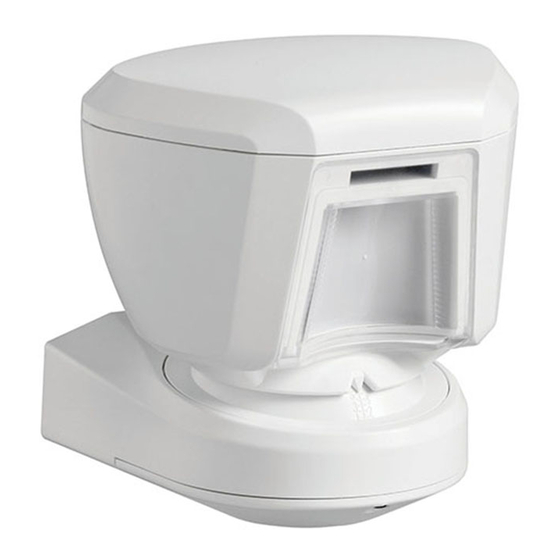
Figure 1: LC-181
Specifications
Optical
Black Mirror Max. Coverage: At least 12 meters (40 ft)/90º.
Detector Technology: 8 independent quad PIR detectors operating in true Quad configu-
ration.
Pet immunity: Small pets.
Electrical
Input Voltage: 8-16VDC
Standby Current: 15mA@12VDC.
Supply Current: 70 mA max. (red and yellow LEDs light steadily)
Low Voltage Detection: If input voltage is below 7.5 VDC
Outputs
Alarm output: Solid State Relay. NC, 100 mA / 30 V, 35 ohm maximum internal resis-
tance. (see Table 4).
Trouble output: Solid State Relay. NC, 100 mA / 30 VDC, 35 ohm maximum internal
resistance. (see Table 4).
Tamper output: NC switch, 50mA / 30 VDC. "Open" by opening detector's cover or
removing it from mounting surface.
Masking detection delay: 120 sec.
Remote LED enable input (TST): High impedance input. Affects LEDs operation only
if internal LEDs selector is set to OFF.
Mounting
Mounting type: Wall mounting
Mounting height: 1.5 - 3.0 meters (5 – 10 ft)
Vertical adjustment: 0º to -10º, in 2.5º steps.
Horizontal adjustment: -45º to +45º, in 5º steps.
Environmental
Operating Temperature: -35°C to 60°C (-31°F to 140°F)
Storage Temperature: -35°C to 60°C (-31°F to 140°F)
Humidity: 95% max.
White light immunity: Above 25000 lux
Physical
Dimensions (height x length x width: 157x147x124mm (6-3/16 x 5-13/16 x 4-7/8").
Weight: 600g (21 oz)
Color: White
Standards Compliance
CE
FCC CFR 47 Part 15
IP 55
Designed to Comply with:
EN 50131-2-2, Security Grade 2, Environmental class IV.
US Patents: 7250605, 6818881, 5693943. Other patents pending.
Figure 2: Coverage Pattern
Installation
DIP Switches Setup
Remove the detector's bottom covers (see Figure 3, steps 4-8) to gain access to the DIP
switches. Set the DIP switches according to Table 1:
Table 1: DIP Switch Setup
DIP SW #
Function
Description
1
LEDs ON/OFF
ON: Motion and masking alarm
LEDs is enabled (ON).
OFF: Motion and masking alarm
LEDs is disabled (OFF). Can be
enabled by TST input (Active "low")
2
PIR Sensitivity
ON: High PIR sensitivity.
OFF: Normal PIR sensitivity.
3
AM ON/OFF
ON: AM on
OFF: AM off *
4
Masking event opens
ON: masking event reported to panel
Alarm relay (EN standard)
as TROUBLE and ALARM (EN
standard). Trouble and Alarm relay
opens at the same time.**
OFF: masking event reported to
panel as TROUBLE (Trouble relay
opens).
*Switching from OFF to ON resets the detector for a stabilization period of 60 sec. and
causes the detector to re-adapt to its current surroundings. Remain at a distance of at least
0.5 m (1.5 ft.) from the detector to prevent disruption of this process.
**Use ON for EN approved control panels / installations. However, many installers prefer
not to have the ALARM relay opened on a masking event.
Installation
Bracket installation (see figure 3) – firmly fix the bracket on a stable wall or pillar. The
orientation of the fixed bracket should be as parallel as possible to the surveyed ground
surface.
Wiring
Perform wiring (see figure 3, step 8 - 10)
Adjustments
Adjust detector's horizontal and vertical angles (see Fig. 4, steps 1 - 6), according to the
surveyed ground surface and close the detector, as shown in Fig. 3, steps 7 - 12.
The vertical angle indicator position for various installation height and coverage distance
combinations is detailed in Table 2 (the information refers to a relatively flat surveyed
area. however, in any case the correct installation should be verified by walk-test).
Table 2: Vertical Adjustment Reference
Mounting Height
Coverage Distance
2m / 6.7ft
4m / 13ft
3.0m / 9,8ft
-
1
2.5m / 8,2 ft
1
1
2.0m / 6,7 ft
1
2
1.5m / 4,9 ft
2
3
Note: The grayed-in cells in Table 2 are the installation alternatives recommended for
further reducing false alarms from pets.
Note: To decrease false alarms, which can be triggered by pets, it is recommended to
install the detector at a height of 2 to 2.5 meters from the ground surface. In addition, ver-
tical adjustment must be fixed on #4 or #5 position. It is recommended to aim the detector
at a background such as walls, houses, fences but not at open space.
Test
A. The detector enters Walk-Test mode after one of the following occurs:
• The 60-second stabilization period ends.
• DIP-SW1 position changes from OFF to ON.
• TST input state changes from OFF to ON.
Note: Regardless of the DIP-SW1 and TST input settings, the Alarm and AM LED indi-
cations are enabled in Walk-Test mode. Crossing a single beam causes the red LED to
double-blink.
B. Walk into the detector's field of view at the expected far edge of the coverage area. Ver-
ify that each time your motion is detected the red LED lights for 2 seconds and the control
panel receives the alarm. If required, perform detector's horizontal / vertical readjust-
ments.
Important! Instruct the user to perform walk test at least once a week, to verify proper
operation of the detector.
C. Place a piece of cardboard on the detector's front side, to deliberately mask the optical
window. After 2 minutes, the yellow LED should light (see Table 3) and the alarm control
panel should receive the masking alarm.
D. Remove the masking from the detector's front side. The LED should extinguish (after
Default
about 30 seconds).
ON
Table 3: LED Operation
Event/Status
Low voltage
OFF
Warm-up (60sec.)
Self-test failure
ON
AM detection
ALARM
OFF
Crossing Beam during Walk-Test
Table 4: Relay Outputs
Event/Status
Complete power failure
Standby
Low voltage
Self-test failure
AM detection DIP-SW4 = ON
AM detection DIP-SW4 = OFF
Alarm
6m / 20ft
8m / 26ft
10m/33 ft
12m/39 ft
2
2
3
3
2
3
4
4
3
4
5
5
4
5
5
-
Indication
Red flashing
Yellow + Red flashing alternately
Yellow + Red flashing simultaneously
Yellow ON
Red ON for 2 sec.
Red Double blink
Relay Output
Trouble
Alarm
Open
Open
Closed
Closed
Open
Closed
Open
Closed
Open
Open
Open
Closed
Closed
Open for 2 sec.
Advertisement

Related Manuals for DSC Outdoor Octa-Quad LC-181


Summary of Contents for DSC Outdoor Octa-Quad LC-181
- Page 1 Humidity: 95% max. Wiring White light immunity: Above 25000 lux Perform wiring (see figure 3, step 8 - 10) Physical Adjustments Dimensions (height x length x width: 157x147x124mm (6-3/16 x 5-13/16 x 4-7/8"). Adjust detector's horizontal and vertical angles (see Fig. 4, steps 1 - 6), according to the Weight: 600g (21 oz) surveyed ground surface and close the detector, as shown in Fig.
- Page 2 • Reorient or relocate the receiving antenna. Toronto, Canada • www.dsc.com • Printed in Israel • Tech. Support: 1- • Increase the separation between the equipment and receiver. 800-387-3630 (Canada, US), 905-760-3000 •...
- Page 3 • Protección alta contra nieve, lluvia, polvo, viento y la exposición directa a la luz solar. Figura 6: Patrón de la cubierta 3,0 m / 9,8 ft • Protección antisabotaje contra la apertura y a remoción del muro. 9 m (30 ft) 2,5 m / 8,2 ft •...
- Page 4 • Consulte al representante comercial o un técnico de TV/radio experimentado. Toronto, Canadá • www.dsc.com • Impreso en Israel • Soporte técnico: 1-800-387-3630 ¡Advertencia de la FCC! Las modificaciones sin la autorización expresa de Visonic Ltd. (Canadá, Estados Unidos), 905-760-3000 puede anular la autorización del usuario para operar el equipo bajo el reglamento de la...
- Page 5 LC-181 FCC CFR 47, Parte 15 A posição do indicador do ângulo vertical para várias combinações entre a altura de IP 55 instalação e a distância de cobertura é detalhada na Tabela 2 (os dados se referem a uma Instruções de Instalação do Detector de Espelho Externo Octa-Quad™ com Projetado para a conformidade com: área vigiada relativamente plana.
- Page 6 A disponibilidade varia por região; contate seu representante de vendas. receptor está conectado. Toronto, Canadá • www.dsc.com • Impresso em Israel • Assistência Técnica: 1-800-387- • Consulte o revendedor ou um técnico experiente de rádio/TV. 3630 (CA, US), 905-760-3000 Aviso da FCC! Modificações não expressamente aprovadas pela Visonic Ltd.
Need help?
Do you have a question about the Outdoor Octa-Quad LC-181 and is the answer not in the manual?
Questions and answers