Table of Contents
Advertisement
Quick Links
Advertisement
Table of Contents

Related Manuals for Fortinet FortiExtender 311F


Summary of Contents for Fortinet FortiExtender 311F
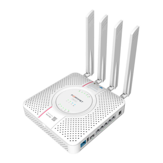
- Page 1 FortiExtender 311F QuickStart Guide...
-
Page 2: Register For Support
® ® 本日、 フォーティネッ ト製品の登録をしてください。 of Fortinet, Inc., in the U.S. and other jurisdictions, and other Fortinet names herein may also be registered and/or common law trademarks of Fortinet. 登録すると次のメリッ トがあります。 All other product or company names may be trademarks of their respective テクニカルサポート... -
Page 3: Packing List
Packing List Product Description All FEX-311F devices feature the same FEX-300F chassis with one (1) CAT16 LTE module pre- installed, as highlighted below. FEX-311F LTE/GPS Antennas Product Features Model Modem FEX-311F FEX-300F chassis with one (1) CAT16 LTE module pre-installed. Mounting Kit Notes: •... - Page 4 Ports, LEDs, & Buttons LED Behavior Description • Green Steady: 1 G network connected. • Green Flashing: 1 G network activity. LAN (1–4) Ports & LEDs. USB 2.0 Port SFP Port & LED WAN Port & LED • OFF: No network connection. Port 4 is PoE PD LAN (802.3at) WAN/LAN LEDs •...
- Page 5 RF Connectors & System LEDs System LEDs on top of FEX-311F Description Power • Green Steady—System has booted up, and is working LTE Modem 1 RF Connectors properly. • Green Flashing—System is booting up. Main MIMO1 DIVERSITY/GNSS MIMO2 • Amber—System is in error state. •...
-
Page 6: Basic Connections
Mounting Holes and Slots Basic Connections Internet Rubber feet slot (one in each corner) Wall-mounting hole LAN/PoE Wall-hanging slots Optional Power Connection 1. Insert one end of an Ethernet cable into the LAN/PoE port on the device. 2. Insert the other end of the Ethernet cable into the PoE LAN port on your FortiGate appliance. - Page 7 IP Configuration Assembly 1. Unscrew the SIM sockets dust cover fastening screw on the bottom of the device, and After you have connected the FortiExtender network interfaces, the device automatically then remove the dust cover that protects the SIM sockets. attempts to obtain an IP address from a DHCP server.
-
Page 8: Installation
Hang on a wall Installation 1. Peel off the drill template sticker, and stick it onto the wall in a desired location. 2. Use the template to mark and drill the pilot holes. The FortiExtender device is designed for placement near a window (desk or wall mount) to 3. - Page 9 Fasten onto a wall Cautions and Warnings 1. Peel off the drill template sticker, and stick it onto the wall in a desired location. Environmental specifications 2. Use the template to mark and drill the pilot holes. Ambient operating temperature: 0°C to 40°C 3.
- Page 10 EU or countries that have implemented the EU Directives and/or spectrum regulation. • Reorient or relocate the receiving antenna. Any Fortinet products not obtained directly from Fortinet or Fortinet’s authorized partners may not comply with EU Directives and Fortinet makes no • Increase the separation between the equipment and receiver.
- Page 11 Note: The full declaration of conformity for this product is available in the link below: Band 38: 2570 — 2620 MHz (Uplink); 2570 — 2620 MHz (Downlink) https://site.fortinet.com/ProductRegulatory/EU Band 40: 2300 — 2400 MHz (Uplink); 2300 — 2400 MHz (Downlink) —...
-
Page 12: Training Services
Create a support account, register and manage your products, download updates, firmware images and release notes, and create technical support tickets. https://support.fortinet.com Fortinet Document Library Up-to-date versions of Fortinet publications for the entire family of Fortinet products. https://docs.fortinet.com Training Services Course descriptions, availability, schedules, and location of training programs in your area.
Need help?
Do you have a question about the FortiExtender 311F and is the answer not in the manual?
Questions and answers