Table of Contents
Advertisement
Quick Links
SECTION
TOPIC
OVERVIEW................................................................
II)
INSTALLATION..........................................................
III)
STATUS INDICATORS.................................................
IV)
LOW VOLTAGE BATTERY DISCONNECT....................... 15
V)
TROUBLESHOOTING................................................... 17
VI)
SPECIFICATIONS......................................................... 19
VII)
BREAKER SPECIFICATIONS/ORDERING GUIDE............ 19
U.S.A. HEADQUARTERS
P.O. Box 1306, Newport Beach, CA 92663
Phone: 714-751-0488 Fax: 714-957-1621
E-Mail: sales@newmarpower.com
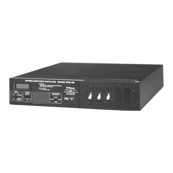
Power Function Manager
MODEL: PFM-400
INSTALLATION / OPERATION MANUAL
A) Materials Provided............................................
B) PFM Mounting..................................................
C) Bus Bar Mounting............................................
D) Input Wiring.....................................................
Quick Connect Wiring Option
E) Output Wiring...................................................
F) Battery Wiring...................................................
G) Status and Alarm Contact Wiring......................
H) Chassis Grounding...........................................
I) Circuit Breakers.................................................
Breaker Installation
Breaker Functions
A) Output Voltage/Current Meter........................... 14
B) "BATTERY ON LINE" L.E.D................................. 14
C) "CHECK SYSTEM" L.E.D.................................... 15
D) LVBD "OPEN" L.E.D........................................... 15
A) Circuit Purpose.................................................. 15
B) Adjusting the Connect/Disconnect Voltages........ 16
Telecom Power Products
www.newmartelecom.com
CONTENTS
(Unit shown with optional
breakers installed)
PAGE
3
3
3
3
3
4
6
9
9
12
12
14
M-PFM400
As of June 2001
EURO WAREHOUSE
Phone:+31-35-603-2494 Fax:+31-35-603-2149
E-Mail: newmareuro@newmarpower.com
1
Advertisement
Table of Contents

Subscribe to Our Youtube Channel
Related Manuals for NewMar PFM-400


Summary of Contents for NewMar PFM-400
-
Page 1: Table Of Contents
Power Function Manager MODEL: PFM-400 (Unit shown with optional breakers installed) INSTALLATION / OPERATION MANUAL CONTENTS SECTION TOPIC PAGE OVERVIEW..............INSTALLATION............A) Materials Provided..........B) PFM Mounting..........C) Bus Bar Mounting..........D) Input Wiring............. Quick Connect Wiring Option Standard Wiring E) Output Wiring........... - Page 2 QUICK REFERENCE CONTENTS Each of the main front or rear panel accessible features of the PFM-400 is illustrated below, along with the page number where information on that particular feature is located. FIGURE 1: PFM FRONT PANEL Low Voltage Battery Ammeter/Voltmeter;...
-
Page 3: I) Overview
OVERVIEW The Power Function Manager (model PFM -400) converts multiple d.c. power sources (or NEWMAR Power Modules) into a fully integrated and multi-functional power sys- tem. The unit provides control, monitoring, paralleling and protection of 12V, 24V or 48V d.c., positive, negative or floating ground power sources. -
Page 4: D) Input Wiring
48 volt position. The unit will operate with positive or negative ground. Simplified Wiring Option: d.c. Quick Connect Wiring Kit A d.c. wiring harness quick connect kit is available from NEWMAR which simplifies parallel wiring installation of multiple Power Modules with the Power Function Man- ager, and also facilitates “hot change-out”... - Page 5 * Positive Ground Systems: Connect Ground Wire to (+) V OUT Terminal and Hot Wire to (-) V OUT Terminal ** Power Plugs shown present only if using NEWMAR QCK d.c. Quick Connect Kit 1) “Hot” input wires are attached to the heavy duty bus bar labeled “INPUT (POWER MODULE)”...
-
Page 6: E) Output Wiring
PFM (either positive or negative ground system). Also illustrated is a typical status and alarm wiring configuration which is discussed later. Note: When paralleling multiple NEWMAR Power Modules, use (+) and (-) V OUT termi- nals only. Do not use V2 terminal. -
Page 7: Unswitched Output
FIGURE 4: Typical PFM d.c. Output and Battery Wiring BBA-400 RTN/ RTN/ RTN/ RTN/GND HOT BATTERY RTN/GND (Pos. or Neg. Ground) To Unswitched Loads To Switched Loads Unswitched Output Use of the PFM unswitched output may be required under certain circumstances; for instance: * PFM output is routed through an external d.c. -
Page 8: Switched Output
Five switched output bus bars are provided for systems with multiple loads or where over-current protection/on-off switching at the PFM is required. Use of any of the switched outputs requires installation of a plug-in breaker (available from NEWMAR) at that position. (See section II-I for installation details and breaker functions. See section VII for available amperages and ordering guide.) -
Page 9: F) Battery Wiring
PFM for ease of installation and to ensure proper connections. This harness is designed for installations which employ NEWMAR Power Modules, though it may be modified for use with other types of equipment, as well, provided they are equipped with Form C or Normally Open (N.O.) failure contacts. - Page 10 TO REMOTE SUMMARY ALARM Status Contact Harness Connection A typical system with six NEWMAR Power Modules is illustrated above. The provided status contact harness may also be used with non-NEWMAR equipment, however, it is likely that each connector on the harness which would normally plug into the power module will require removal and replacement with another suitable for that particular piece of equipment.
-
Page 11: H) Chassis Grounding
Alarm Wiring with NEWMAR DST-20A Distribution Panel NEWMAR's DST-20A is provided with its own four-wire harness for alarm wiring. Plug one end of the harness into the keyed connector on the rear of the DST which is labeled BREAKER STATUS. Note: The harness is reversible, therefore it does not matter which end is plugged in. -
Page 12: I) Circuit Breakers
Circuit breakers must be installed to use any of the switched outputs. The PFM ac- cepts only specially designed plug-in “mid-trip” circuit breakers with auxiliary con- tacts, which are available from NEWMAR. (The mid-trip function is explained later). Refer to the Specifications section for available breaker values and ordering info. - Page 13 3) Prior to installing circuit breakers, make note of the following: The conductor for each breaker position runs straight through to the rear of the PFM so that the breaker in Position 1 (as you face the front) is on the far left, and the Position 1 output terminal (as you face the rear) is on the far right, and so on with each breaker/output terminal position reversed from front to back.
-
Page 14: Status Indicators
Circuit Breaker Function/Mid-Trip Feature The plug-in circuit breaker functions as an on/off switch and provides over-current protection as rated. However, the special mid-trip feature allows the operator to dis- tinguish between a condition where the breaker has been tripped by over-current and where it has been intentionally shut off. -
Page 15: C) "Check System" L.e.d
If either test reveals no voltage is present, check for a blown or missing battery fuse or a bad connection to the battery. C) “CHECK SYSTEM” L.E.D. - Red This L.E.D. illuminates during any of three failure conditions: 1) Loss of d.c. input from one or more of the power modules wired to the PFM provided the loss of output is accompanied by a “FAIL”... -
Page 16: B) Adjusting The Connect/Disconnect Voltages
B) Actuation Voltage Adjustment The factory set actuation voltages are as follows: 12 Volt 24 Volt 48 Volt Disconnect (OPEN) 10.4V d.c. 20.0V d.c. 40.0V d.c. Connect (CLOSE) 12.4V d.c. 24.8V d.c. 50.0V d.c. The connect and disconnect voltages may be adjusted ± 15%. Access to the contactor actuation voltage potentiometers is through the front panel ports labeled “OPEN”... -
Page 17: Troubleshooting
8) Verify the correct connect voltage by turning the variable power supply voltage down until the contactor opens, then slowly raise the supply voltage until the contactor closes. If necessary, slightly adjust the potentiometer up or down, then reverify connect voltage. Repeat this process until the desired connect voltage is achieved. - Page 18 “DISCONNECT” position. “AUTO”. Factory Contact Information If a problem with the PFM-400 persists after you have applied the above-outlined solutions, or if you have any questions about the installation and proper operation of the unit, please contact NEWMAR's Technical Services Manager: Phone: 714-751-0488 —...
-
Page 19: Specifications
Magnetic-Hydraulic Plug-in with Auxiliary Contacts (Normally Open) and Mid-Trip Function UL Listed Telecom Breaker CSA Certified To order additional or replacement breakers for the PFM-400 refer to the following NEWMAR model or Carlingswitch part numbers: Rating NEWMAR Model Carlingswitch P/N...
Need help?
Do you have a question about the PFM-400 and is the answer not in the manual?
Questions and answers