Table of Contents
Advertisement
Quick Links
Advertisement
Table of Contents

Related Manuals for Robe Anolis E-box Daisy


Summary of Contents for Robe Anolis E-box Daisy
- Page 1 QR code for user manual Version 2.8...
-
Page 2: Table Of Contents
5.1 DMX Addr ........................ 22 5.2 Info ........................... 23 5.3 Personality ....................... 23 5.4 Special settings ......................24 6. Robe Ethernet Access Portal (REAP) ................. 25 6.1 Settings on computer ....................25 6.2 Settings on fixtures ....................25 6.3. REAP menu screens ....................25 6.4 Status screen ...................... -
Page 3: Safety Information
1. Safety information FOR YOUR OWN SAFETY, PLEASE READ THIS USER MANUAL CAREFULLY BEFORE POWERING OR INSTALLING YOUR E-BOX! Save it for future reference. DANGEROUS VOLTAGE CONSTITUTING A RISK OF ELECTRIC SHOCK IS PRESENT WITHIN THIS UNIT! Make sure that the available voltage is not higher than stated on the fixture. Always disconnect the fixture from AC power before removing its cover. - Page 4 installed and used in accordance with the instructions, may cause harmful interference to radio communications. However, there is no guarantee that interference will not occur in a particular installation. If this equipment does cause harmful interference to radio or television reception, which can be determined by turning the equipment off and on, the user is encouraged to try to correct the interference by one or more of the following measures: - Reorient or relocate the receiving antenna.
-
Page 5: Fixture Description
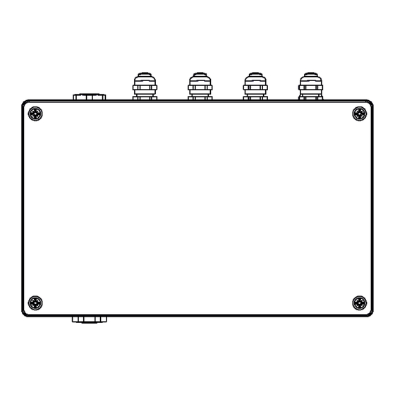
2. Fixture description 2.1 E-box Daisy A - Top cover B - Top cover screws C - Mounting holes D - Antenna cover E - Display F - Control buttons G - Screws of terminal blocks cover H - Terminal blocks cover 1 - Power IN (cable gland M20x1.5) 2 - DMX OUT(cable gland M12x1.5) 3 - DMX IN (cable gland M12x1.5) - Page 6 E-Box Daisy - connection points Power IN D+ D- 0V D+ D- 0V NC NC RD- NC NC RD+ TD- TD+ NC NC RD- NC NC RD+ TD- TD+ DMX OUT DMX IN Ethernet OUT Ethernet IN Fuse T 0.5A H Data OUT 0V D- D+ LED Output...
-
Page 7: E-Box Star
2.2 E-box Star A - Top cover B - Top cover screws C - Mounting holes D - Antenna cover E - Display F - Control buttons G - Screws of terminal blocks cover H - Terminal blocks cover 1 - Power IN (filler plug M25 x 1.5/ cable gland M20x1.5) 2 - DMX OUT (cable gland M12x1.5) 3 - DMX IN (cable gland M12x1.5) 4 - Ethernet OUT (cable gland M12x1.5) - Page 8 E-Box Star - connection points Power IN NC NC RD- NC NC RD+ TD- TD+ D+ D- 0V NC NC RD- NC NC RD+ TD- TD+ D+ D- 0V DMX OUT DMX IN Ethernet OUT Ethernet IN Fuse T 0.5A H Data OUT Data OUT Data OUT...
-
Page 9: E-Box Lite
2.3 E-box Lite A - Top cover B - Top cover screws C - Mounting holes D - Antenna cover E - Display F - Control buttons G - Screws of terminal blocks cover H - Terminal blocks cover 1 - Power IN (cable gland M20x1.5) 2 - DMX OUT (cable gland M12x1.5) 3 - DMX IN (cable gland M12x1.5) 6 - LED Output (cable gland M20x1.5) - Page 10 E-Box Lite - connection points DMX OUT DMX IN Power IN LED OUTPUT Data OUT...
-
Page 11: Mounting
3. Mounting Fixture must be installed by a qualified electrician in accordance with all national and local electrical and construction codes and regulations. Setting and addressing the E-box without top cover can be done by a qualified person only! Note for cable glands. We recommend to apply an adequate layer of the paste LOCTITE 5331 on the plastic holder of the cable gland before inserting it into the body of the gland and an adequate layer of the paste LOCTITE 577 on the thread of the gland body. - Page 12 Power connection Core (EU) Braun Blue Green/yellow Core (US) Black White Green DMX connection Data + Data - Data ground (shielding) Ethernet connection Function Eminere connection Cable CE Leader: Wire Power Connection Wire Data Connection Brown Orange Data - Blue Purple Data + Yellow/Green...
- Page 13 The tables below state max. theoretical number of Emineres connected to the one LED output of the E-box without using Booster boxes. Number of Emineres depends on voltage and cable length. The following tables apply for the Standard mode of E-boxes. EMINERE 1(Eminere Side 1) Voltage Cable length *...
- Page 14 Example 2: E-box Star, voltage=230V, cable length=100m,fixture= Eminere 4, total number of Emineres 4 =16 pcs, without Booster box, Standard mode. LED Output 1 =16 x Eminere 4 LED Output 2 = not connected LED Output 3 = not connected LED Output 4 = not connected LED Output 5 =not connected LED Output 6 =not connected...
- Page 15 The Booster box To compensate a voltage drop in a large installation, the Booster boxes have to be connected in the chain of Eminere modules. Example: E-box Daisy, Power supply= 230V, Total cable length=70m, Standard mode, type of Eminere: Eminere 2 The Booster box has to be connected after every 45th Eminere 2 (fixture 45 and fixture 90 from 94 fixtures).
- Page 16 200 m 4,8,12,16,20,24,28,32,36,40, 11,22,33,44,55,66, 16,32,48,64,80 23,46,69,92 44,48,52,56,60,64,68,72,76,80 77,88 ,84,88,92 Eminere 3 Max. possible number of Emineres 3= 64 Eminere Side 3 Voltage Cable length 120V 190V 230V 277V 10 m 28,56 20 m 28,56 30 m 19,38,57 50 m 12,24,36,48,60 29,58 70 m 8,16,24,32,40,48,56...
-
Page 17: Eminere Modes
Emineres Inground. DMX addressing of connected LED modules has to be done manually by means of RDM (software RDM Manager and the device Robe Universal Interface). Only connected LED modules will be shown in the RDM Manager. - Page 18 Examples of RDM manager screenshots. Initial screen of the RDM manager - Standard mode: E-box is shown Connected LED module(s) is (are) shown Initial screen of the RDM manager - Pass Through mode: Only connected LED module(s) is (are) shown...
- Page 19 Click on the LED device to show and set options in the Control panel Occupied channels are displayed in the window DMX patch Click on the green arrow to save adjusted values DMX preset and number of used channels DMX address If some DMX Preset shows xx instead of number of channels, it means that DMX preset is reserved for future using (e.g.
- Page 20 Options in the control panel: Last Eminere on each DMX line may be terminated by setting the ‘Manufacturer PID’ ’Terminator active’ to ‘1’,...
- Page 21 The option "Pixel swap" from RDM control panel allows you to swap the pixel order. Example: Desired pixel order Eminere turned by 180°-->Pixels 5 and 6 light in reverse order.
-
Page 22: E-Box Menu
5. E-box menu The E-box is equipped with 2-row LCD display and four buttons which allows to address the fixture and set the fixture´s behaviour according to your needs. The four control buttons have the following functions: - ESCAPE button- to escape function or menu. - ENTER button- to select a function or confirm adjusted value. -
Page 23: Info
5.2 Info Use this menu to read useful information about the fixture. Software version - select this menu item to read software versions of the E-box and connected Emineres. Databox - version of the E-box. WL - version of installed wireless DMX module. IP Addr - - IP address. -
Page 24: Special Settings
* If wireless DMX module is installed. Software Update - The menu item switches the the E-box to the update mode. If the software update is done by means of the software ROBE RDM Uploader, switching the E-box to the update mode will be done automatically. -
Page 25: Robe Ethernet Access Portal (Reap)
Art-Net mode. 6.3. REAP menu screens Type the IP address of the ROBE fixture to your web browser, e.g. http://2.247.92.33, enter the user name: robe and the password: 2479, the first menu screen of the ROBE fixture will appear. 6.4 Status screen The screen gives you a fast overview of fixture settings. -
Page 26: Personality Screen
6.5 Personality screen The screen allows you to change some fixture settings by clicking on the icon in a corresponding table . 6.6 Settings screen The screen allows you to change password to REAP. -
Page 27: Software Update
2. Option “Pass-Thr” is selected from the menu “E-box mode” and LED modules are connected in series. Set the E-box to the Standard mode and switch it off/on. Only E-box will be shown in the ROBE Uploader. You have to use the file EminereEbox.lib in the ROBE Uploader for software update of the E-box and connected LED modules. - Page 28 In the second step you have to set the E-box to the Standard mode and switch it off/on. Use the file EminereEbox.lib in the ROBE Uploader for software update of the E-box. Only E-box will be shown in the ROBE Uploader.
-
Page 29: Technical Specifications
8. Technical specifications E-box Daisy Number of inputs: Input voltage 120-277 V AC; 50/60Hz Power consumption 5W (self-consumption of the E-box) Fuse T 0.5A H LED Output Number of outputs Voltage 120-277 V Max. Current Control 2-row LCD display & 4 buttons Supported protocols USITT DMX 512, ArtNet, sACN, RDM W-DMX control (optional) - Page 30 E-box Star Number of inputs: Input voltage 120-277 V AC; 50/60Hz Power consumption 5W (self-consumption of the E-box) Fuse T 0.5A H LED Outputs Number of outputs Voltage 120-277 V each output) Max. current 16A in total for all outputs Warning: In view of the fact that e E-box Star has only one power input, outputs to Emineres cannot be so loaded as outputs for Emineres at the E-box Pro.
- Page 31 E-box Lite Number of inputs: Input voltage 120-277 V AC; 50/60Hz Power consumption 5W (self-consumption of the E-box) Fuse T 0.5A H LED Output Number of outputs Voltage 120-277 V Max. current Control 2-row LCD display & 4 buttons Supported protocols USITT DMX 512, RDM W-DMX control (optional) Connection...
-
Page 32: Disposing Of The Product
DMX chart ver. 3.3 (Eminere), DMX chart ver. 1.3 (Calumma), Menu Test program removed March 5, 2024 Specifications are subject to change without notice. Copyright © 2019-2024 Robe Lighting - All rights reserved Made in CZECH REPUBLIC by ROBE LIGHTING s.r.o. Palackeho 416/20 CZ 75701 Valasske Mezirici... - Page 33 DMX protocol DMX protocol for: Eminere 1/2/3/4; Eminere Side 1/2/3/4; Eminere Inground 2/4; Eminere Remote 1/2/3/4; UVinere 2/4; UVinere Remote 1/2/4 Version: 3.3 (23 modes in total), software version 3.0 and higher Mode/Channels in all Mode 1: RGBW(A)-8bit, Mode 2: RGB 8-bit, Mode 3: full RGBW(A) 8-10 Mode 4: White-full control, Mode 5: Reduced RGBW(A) Mode 6- Reduced RGBW(A)+white control...
- Page 34 DMX protocol Mode/channels Type of Function Value control (21-1800K, 66-2700K, 91-3200K,141-4200K, 211-5600K, 255- 6500K) Virtual Colour Wheel No function step White 1800 K step White 2700 K step step White 3200 K White 4200 K step 9-10 White 5600 K step 11-12 White 6500 K step...
- Page 35 Random strobe-effect from slow to fast 192-223 proportional Shutter open 224-255 step Dimmer 0-255 Light intensity coarse (0-100%) proportional Dimmer Fine 0-255 Light intensity fine proportional Copyright © 2022-2024 Robe Lighting s.r.o. - All rights reserved All Specifications subject to change without notice Page 3...
- Page 36 Dimmer 0 - 255 Light intensity coarse (0 - 100%) proportional Dimmer Fine 0 - 255 Light intensity fine proportional Copyright © 2022-2024 Robe Lighting s.r.o. - All rights reserved All Specifications subject to change without notice Page 4...
- Page 37 DMX protocol DMX protocol for: Eminere 1/2/3/4; Eminere Side 1/2/3/4; Eminere Inground 2/4; Eminere Remote 1/2/3/4; Version: 3.3 (23 modes in total) Mode/Channels in all Mode 17: RGBW(A) pixels, Mode 18: RGB pixels, Mode 19: TW pixels, 21-23 Mode 20: PW dimmer pixels Reserved Pixel modes Mode/channels...
- Page 38 Dimmer 4 0 - 255 Light intensity coarse (0 - 100%) proportional Dimmer Fine 4 0 - 255 Light intensity fine proportional Copyright © 2022-2024 Robe Lighting s.r.o. - All rights reserved All Specifications subject to change without notice Page 6...
- Page 39 DMX protocol DMX protocol for Calumma - All sizes - MC and SC Version: 1.3 (16 modes in total) Mode/Channels in all Mode 1- RGBW(A)-8bit, Mode 2- RGB 8-bit, Mode 3- full RGBW(A) 8-10 Mode 4- White-full control, Mode 5- Reduced RGBW(A) Reserved Mode 6- Reduced RGBW(A)+white control, Mode 7- Full control Mode 7-Full RGBW(A)+virt.
- Page 40 DMX protocol Mode/channels Function DMX Value Type of control White 1800 K step White 2700 K step White 3200 K step White 4200 K step step 9-10 White 5600 K 11-12 White 6500 K step Blue (Blue=full, Red+Green+White/Amber=0) step proportional 14-23 Red=0, Green->up,Blue =full, White/Amber=0 step...
- Page 41 224-255 Shutter open step Dimmer 0 - 255 Light intensity coarse (0-100%) proportional Dimmer Fine 0 - 255 Light intensity fine proportional Copyright © 2022-2024 Robe Lighting s.r.o. - All rights reserved All Specifications subject to change without notice Page 3...
- Page 42 Dimmer 0 - 255 Light intensity coarse (0 - 100%) proportional Dimmer Fine 0 - 255 Light intensity fine proportional Copyright © 2022-2024 Robe Lighting s.r.o. - All rights reserved All Specifications subject to change without notice Page 4...
Need help?
Do you have a question about the Anolis E-box Daisy and is the answer not in the manual?
Questions and answers