Advertisement
Instructions
Power plug wiring:
For either 110 or 220VAC, the GREEN wire is the ground wire. The WHITE and BLACK wires are hot wires.
For Plasma Cutting:
- Wear a Lotos auto darkening plasma cutting helmet (Figure 1.1, not included in the box. To purchase, please go to our website.) to protect your eyes from harmful plasma cutting arc radiation and safety gloves to protect your hands during welding.
![]()
- Connect the machine gas inlet (on the back of the machine, Figure 1.2) with an air compressor (Figure 1.3) and set the air pressure to 65-70 PSI. (The Air Regulator is optional if your air compressor has the capability to control output air pressure.)
![]()

- Connect your plasma cutting torch and ground cable to the front panel of the machine. Make sure the ground cable is connected on the right hand side where the "+" sign is located.


![]() Set TIG Weld
Set TIG Weld![]() /Stick Weld
/Stick Weld ![]() /Plasma Cut to Plasma Cut mode.
/Plasma Cut to Plasma Cut mode.- Set "2.5S/5S" to "2.5S" mode.
- Set "Machine/PEDAL" to "Machine" mode.
- Adjust current dial between 10 and 50 amps.
 Set TIG Weld
 /Stick Weld
  /Plasma Cut to Plasma Cut mode.
- Attach the ground clamp to the metal you want to cut. Grind the metal to make sure the clamp is securely attached to the work piece. Press the trigger of the torch and make sure the air is flowing. Finally, move the torch head to the work piece and start cutting.
- Change your consumables (tip, electrode, ring and cup) if they are worn out. The consumables' type is PCS. If you want to cut the perfect circle or perfect straight line, order a Lotos LCK roller guider compass kits from our website www.uwelding.com.
For TIG Welding:
- Wear our auto darkening helmet and gloves to protect your eyes and hands from any harmful welding arc. (Please see step 1 in Plasma Cutting.)
- Connect the machine gas inlet (on the back of the machine, Figure 1.5) to the argon regulator and adjust the knob to set gas pressure between 15 and 20 min/L (an argon regulator is necessary, Figure 1.6.)


- Connect your TIG torch and ground cable to the front panel of the machine.
- Make sure the ground cable is connected on the right hand side where the "+" sign is located
- Set TIG Weld/Stick Weld/Plasma Cut to TIG Weld mode (refer to Figure 1.4)
- Set "2.5S/5S" to "2.5S" mode.
- Set "Machine/PEDAL" to "Machine" mode.
- Adjust current dial from 10 to 200 amps (Figure 1.8).


- If you want to dynamically control the welding heat, please use a foot pedal (not included in the box. To purchase, please go to our website). Then connect the "on/off" connector to your foot pedal and leave the wire of the TIG torch unplugged.
- Set TIG Weld/Stick Weld/Plasma CUT to TIG Weld mode (refer to Figure 1.4).
- Set "2.5S/5S" to "2.5S" mode.
- Set "Machine/PEDAL" to "Pedal" mode.
- Adjust current dial between 10 and 200 amps (Figure 1.9).


- TIG torch head parts (Figure 1.9) and assembly (Figure 1.10)
(The tungsten is not included in the picture; please buy proper DC Lotos tungsten electrodes.) Grind and sharpen the tungsten before first use.


For Stick/Arc/MMA Welding:
- Wear our auto darkening welding helmet and gloves to protect your eyes and hands from any harmful welding arc. (Please see step 1 in Plasma Cutting.)
- You don't need to connect the machine to any gas or air supply. It's a plug and play.Panel connection instructions:
- Set TIG Weld/Stick Weld/Plasma Cut to Stick Weld mode (refer to Figure 1.4).
- Set "2.5S/5S" to "2.5S" mode.
- Set "Machine/PEDAL" to "Machine" mode.
- Adjust current dial between 10 and 200 amps (Figure 1.11).


Please be sure to turn off the machine when you switch from one function to another. This is important, because otherwise the machine could be damaged.
All accessories and consumables can be purchased at www.uwelding.com or Lotos's authorized resellers.
Introduction
Overview
Feel free to check out our other products at www.uwelding.com.
This User Manual documents policies and procedures for proper operation of the equipment.

Be sure to review the contents of this manual before attempting to operate the equipment. This manual should be located where it can be easily referenced by all users of the machine.
Audience
This manual assumes that all individuals reading the manual and using the welder/cutter are able, qualified, and/or certified to operate this type of machinery.
Safety Precautions
Read Before Using
Overview
Protect yourself and others from injury — read and follow these precautions.
Caution Recommendations

Welding and arc cutting can cause bodily injury.
- Do NOT switch off the machine while machine is in operation for internal circuitry can be damaged.
- Connect the machine to a UL-approved outlet only. Do not hard wire the machine directly to the power source.
- Wear safety goggles at all times. This will darken the arc that is generated by the machine and protect your eyes from harmful rays.
- All machine operators should be technically certified for welding/cutting.
Avoiding Fatal Electric Shock

- Isolate yourself from both the earth and the work piece.
- Make sure that your working area is nonflammable and explosive-free.
Avoiding Harmful Smoke, Gases, and Vapors that can injure or kill.

Welding produces fumes and gases. Breathing these fumes and gases can be hazardous to your health.
Avoiding Harmful Arc Emissions/Rays that can burn eyes and skin.

Arc rays from the welding process produce intense visible and invisible rays that can burn eyes and skin. Sparks fly off from the weld.
- Wear appropriate clothing and a welding or cutting mask to protect your eyes and skin.
- Use appropriate screen or curtain to prevent emissions from reaching individuals near the work area.
- Ensure that your working area contains no flammable items; and that none are nearby.
![]()
Welding and cutting spray can ignite.
Avoiding Harmful Noises that can damage hearing.

Noise from some processes can damage hearing.
- Wear protective earplugs while operating machine.
Welding or Cutting can cause Fire or Explosion.

Welding, cutting, and allied processes can cause fire or explosion if precautionary measures are not followed.
- Develop adequate procedures, and use proper equipment to do the job safely.
- Remove combustible materials from a sphere with a minimum radius of 35 feet around the work area or move the work to a location well away from combustible materials.
Burn Protection: HOT PARTS can cause serious burns.

The work piece and equipment get hot. The hot metal, hot work piece, and hot equipment can cause burns.
- Use approved helmets or hand shields that provide protection for the face, neck, etc.
- Wear approved safety goggles or glasses with side shields, even under your helmet.
- Wear dry, hole-free insulated gloves.
Protect eyes from FLYING METAL or DIRT.

- Welding, chipping, wire brushing, and grinding cause sparks and flying metal.
- Wear approved safety glasses with side shields, even under your welding helmet.
PACEMAKERS AND WELDING: MAGNETIC FIELDS can affect implanted devices.

Electric arc welding and cutting processes produce intense electric and magnetic (electromagnetic) fields. The function of pacemakers can be affected by strong electromagnetic fields.
- Persons with a pacemaker should not go near welding or cutting operations until they have consulted their doctors and obtained information from the manufacturer of the device.
CYLINDER HANDLING: it can explode if damaged.

Shielding gas cylinders contain gas under high pressure. If damaged, a cylinder can explode. Be sure to treat gas cylinders carefully.
- Keep cylinders away from any welding or other electrical circuits.
- Protect compressed gas cylinders from excessive heat, mechanical shocks, physical damage, slag, open flames, sparks, and arcs.
- Install cylinders in an upright position by securing to a stationary support or cylinder rack to prevent falling or tipping.
If you encounter any difficulties during set up or operation:
- Consult this manual.
- Contact Lotos Customer Service by visiting http://www.uwelding.com/about-us/contact-us/.
Equipment
General Overview
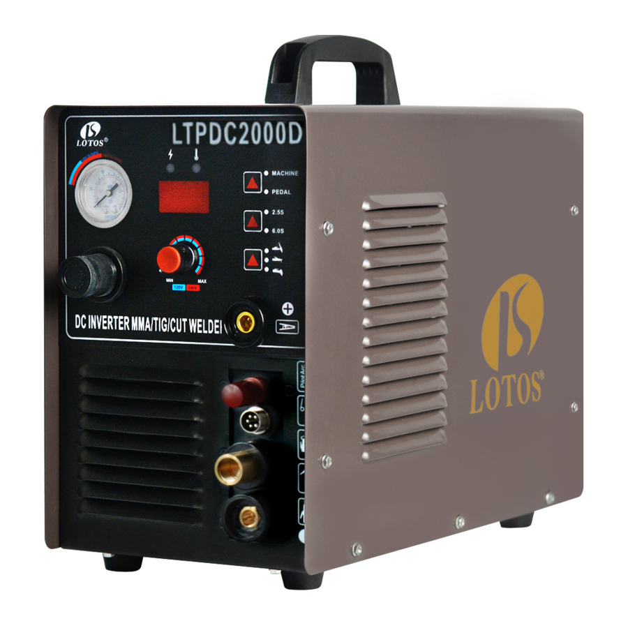
The LOTOS LTPDC2000D is a first to market multi-process welder that allows the user to DC TIG/ STICK and Plasma Cut all from one portable machine. The LTPDC2000D combines three processes into one with a 200amp DC TIG Welder, a 200amp Stick Welder, and a 50amp Pilot Arc Plasma Cutter all available with the flip of a switch, making it the perfect model for DIY users!
Main Characteristics
- Stabilization
- Reliability
- Portability
- Power efficiency and low noise output
- High cutting speed
- Smooth cuts
Specifications
| General | Model Name | LTPDC2000D |
| Functions | 50 A Pilot Arc Plasma Cutter 200 A TIG Welder 200 A STICK Welder | |
| Dimension with handle LxWxH | 19.5''x 7.9''x 14'' | |
| Weight | 25.8 lbs (11.72 kg) | |
| Input voltage | 110-220 V, 1-PH, 50/60 Hz | |
| Power supply type | Inverter - MOSFET | |
| Accessories | Pilot Arc Plasma Cutting Torch | 50 A 13.3 ft. (4m) |
| TIG welding torch | 200 A 12.9 ft. (3.93m) | |
| Arc/Stick clamp | 200 A 6.5 ft. (1.98m) | |
| Argon regulator | 0-250 psi | |
| Air regulator | 0-150 psi | |
| Plasma Cutting | Rated input current | 110 V, 1-PH, 50 A 220 V, 1-PH, 35 A |
| Output current | 10-50 A | |
| Duty cycle @ 40°C (104°F) | 60% @ 50 A 100% @ 35 A | |
| Gas supply | Clean, dry, oil-free air | |
| Recommended gas inlet flow rate / pressure | 3.6 scfm @ 65 psi | |
| DC TIG Welding | Power usage | 35 A @220 V, 50A @ 110V |
| Output current | 15-200 A | |
| Material can weld | Steel, Stainless, Moly, Ferrous | |
| Duty cycle @ 40°C (104°F) | 60% @ 200 A 100% @ 105 A | |
| No load voltage | 62 V | |
| Working voltage | 16.9 V | |
| Gas supply | Clean, dry, oil-free argon gas | |
| Starting mechanism | High Frequency Start / HF Welding | |
| Recommended gas inlet flow rate | 2-5 L/M | |
| DC Stick Welding | Power usage | 45 A @ 220 V, 55 A @110 V |
| Output current | 15-200 A | |
| Material can weld | Steel, Stainless, Moly, Ferrous | |
| Duty cycle @ 40°C (104°F) | 60% @ 200 A 100% @ 95 A | |
| No load voltage | 62 V | |
| Working voltage | 25 V | |
| Starting mechanism | High Frequency Start / HF Welding |
INSTALLATION
Figure 2.1: Adjustor Diagram 1

Figure 2.2: Adjustor Diagram 2

Figure 2.3: Air Regulator Configuration

Figure 2.3: Plasma Cutting Diagram

Figure 2.4: TIG Welding without Foot Pedal Diagram

Figure 2.4: TIG Welding with Foot Pedal Diagram

Figure 2.6: Arc/Stick/MMA Welding Diagram

Power Plug Wiring
Connect this welding & cutting equipment with a power supply of 110 or 220V AC. For the wiring, please note that:
For 110VAC,
- The green wire with yellow stripe is the ground wire
- The red/brown wire is the hot wire
- The blue/black wire is the neutral wire
For 220VAC,
- The green wire with yellow stripe is the ground wire
- The red/brown wire is positive 110VAC
- The blue/black wire is negative 110VAC
Connect the earth terminal with the earth cable (minimum diameter of 2.5 mm2.)
Connection of the Output Cables
- Install welding torch according to the picture.
- Connect the one-knob connector air plug to the corresponding connector on the panel board and fasten the screw.
- Plug the air plug of the back cable to "+"of the air socket on the panel board, and fasten it in clockwise. Connect earth clamp with work piece.
Power Supply Switch
If the power switch is on, the built-in fan start working and the current meter displays the current value.
Function Switch
The function switch enables the machine to alternate between MMA, TIG, and CUT welding according to the practical welding task requirement.
- TIG Welding
- Connect the copper nozzle in the back of the machine to the argon tank with the hose. The gas supply system includes the gas bottle, air regulator, and gas hose. Connect the parts of the gas system firmly to prevent gas leakage. - Install the argon torch according to the drawing.
- Connect the copper screw on the cutting torch to the output terminal of the one-knob of the front panel and fasten it clockwise to avoid gas leakage.
- Connect the plug of the closed circuit to the "+" socket on the panel board. Connect the earth clamp to the work piece.
Function Switch
- MMA Function
- Connect the plug of the electrode holder to the (-) socket on the front panel.
- Connect the plug of the ground clamp to the (+) socket on the front panel.
- Plasma Cutting Function
- Use the gas hose to connect to one of the terminals on the air regulator and connect the other terminals to the copper tub.
- Connect the copper nut of the cutting torch to the knob on the panel board.
Connect the plug of the ground clamp to the (+) socket on the front panel.
Welding Current Output Setting
According to practical demand, set the parameters of the current output by the operation of "ARC," "TIG," or "CUT."
Air/Argon Regulator Installation

OPERATION
TIG Welding Function
- While this welding & cutting equipment is operated, the power supply indicator is on, and the built-in fan will function.
- Switch to the TIG welding function mode.
- Press the gas release button and modulate the volume of gas output to the required value.
- Press the button on the welding torch and the electromagnetic valve will function. The sound of releasing electricity is audible and there is gas coming out of the welding torch.
Please note: Before the initial welding operation, press the button on the welding torch for several seconds in order to remove the gas inside the gas tub, and the welding operation is accessible. There is gas output within a few seconds after the welding operation, that is a special design to protect the welding point before it cools down. Therefore, after the arc is gone, maintain the welding position until the heat produced during the welding operation dissipates. - The welding current output is adjustable, according to the thickness of the welding material and required craftsmanship.
- Maintain a distance of 1-4mm between the tungsten electrode and the work piece. Press the button on the welding torch. HF electricity will release between the welding electrode and the work piece. After the arc starts, the splash of the HF arc will vanish and the welding operation can begin.
MMA Function
- Switch to MMA welding mode.
- While this welding & cutting equipment is operated, the power supply indicator is on and the built-in fan will function.
- According to the thickness of the work piece, adjust the welding current output and choose the rod, then the MMA welding can begin.
Plasma Cutting Function
- Switch to the plasma-cutting mode.
- While this welding & cutting equipment is operated, the power supply indicator is on and the built-in fan will function.
- Release the regulator valve and modulate the pressure and volume of output gas.
- Press the cutting torch button. The sound of releasing electricity is audible and there is gas coming out of the welding torch.
- According to the thickness of the work piece, adjust the current output, and then the plasma cutting can begin.
- Put the nozzle of the cutting torch to the work piece and press the welding torch button. The sound of the HF arc vanishes and the cutting operation can begin. After the arc starts, maintain a distance of about 1mm in order to protect the nozzle from possible damage.
- In case of difficulty with starting the arc, it is recommended to reduce the pressure of the gas output.
- If the nozzle is damaged, adjust the pressure of the gas output.
Instruction Notes
Working Environment
- The location in which this welding & cutting equipment is installed should be free of dust, corrosive chemical gases, flammable gases or materials, and be at no more than 80% humidity.
- Avoid welding & cutting in the open air unless sheltered from the sun, rain, and snow.
The temperature of the working environment should be maintained within -10°C to +40°C. - Keep this welding & cutting equipment 30cm away from the wall.
- Ensure the working environment has good ventilation.
Safety
- Ventilation
This welding & cutting equipment is small, compact in structure, and has excellent current output performance. Fans are required to remove heat generated by this cutting equipment while the machine is being operated.
![]()
Maintain good ventilation of the louvers of this welding & cutting equipment. The minimum distance between this welding & cutting equipment and any other object in or near the working area should be 30 cm. Good ventilation is of critical importance for the normal performance and service life of this welding & cutting equipment. - Welding cannot be performed if equipment is overloaded.
A sudden halt may occur while the cutting operation is carried out if the machine is in over-load status. Under this circumstance, it is unnecessary to restart the equipment. Keep the built-in fan running to bring down the temperature inside the equipment. - Beware of over-voltage.
Regarding the power supply voltage range of the welding & cutting machine, please refer to the "Specifications" table. This equipment has automatic voltage compensation, which enables it to maintain the voltage within the given range. If the power supply input voltage current exceeds the stipulated value, it is possible to damage the components of this equipment. - An earth terminal is available for this welding & cutting equipment.
Connect the earth cable to avoid static and electric shock. It is not recommended to touch the output terminal while welding and cutting. An electric shock may occur.
Maintenance
Exposure to extremely dusty, damp, or corrosive air is damaging to this welding & cutting machine.
In order to prevent any possible failure or fault of this equipment, clean the dust out at regular intervals with clean and dry compressed air of required pressure.
Please note: Lack of maintenance can lead to the unavailability and cancellation of the guarantee; the guarantee of this welding and cutting equipment will no longer be available if attempts have been made to take the machine apart or the factory-made sealing of the machine has been opened.
Troubleshooting
The following trouble shooting guide is for your reference only. Lotos Technology will NOT take any liability or responsibility for any injury or damage caused in such action(s). Always turn off electrical power and air supply before performing inspection and reconnection.
Only qualified technicians are authorized to undertake the repair of this equipment in the case of machine failure.
| Fault Symptoms | Rectification |
|
|
|
|
|
|
|
|
|
|
|
|
|
|
|
|
|
|
LTPDC2000D Other Accessories
 GC01 Ground Cable |  PT01 |
 NCP243 |  PCS22 |
 PC S33 |  PC S77 |
 HM03 |  HM02 |
 FP05 |  TA01 |
Documents / Resources
References

Download manual
Here you can download full pdf version of manual, it may contain additional safety instructions, warranty information, FCC rules, etc.
Advertisement


Need help?
Do you have a question about the LTPDC2000D and is the answer not in the manual?
Questions and answers