Table of Contents
Advertisement
Available languages
Available languages
Quick Links
FBOEL1333-30
FBOEL1340-30
SINGLE OR DOUBLE WALL OVENS
MODEL NUMBER SERIES: FBOEL1333-30 | FBOEL1340-30
INSTRUCTION MANUAL &
INSTALLATION GUIDE
5015011
Conforms to UL STD 858 & CSA / ANSI STD Z21.1
Certified to CSA STDs C22.2#61 & CSA STD 1.1
Read these instructions carefully before using your appliance, and keep them carefully.
If you follow the instructions, your appliance will provide you with many years of good service.
10/2023
Advertisement
Chapters
Table of Contents

Related Manuals for Forno FBOEL1333-30


Summary of Contents for Forno FBOEL1333-30
- Page 1 FBOEL1333-30 FBOEL1340-30 SINGLE OR DOUBLE WALL OVENS MODEL NUMBER SERIES: FBOEL1333-30 | FBOEL1340-30 INSTRUCTION MANUAL & INSTALLATION GUIDE 5015011 Conforms to UL STD 858 & CSA / ANSI STD Z21.1 Certified to CSA STDs C22.2#61 & CSA STD 1.1 Read these instructions carefully before using your appliance, and keep them carefully.
-
Page 2: Table Of Contents
TABLE OF CONTENTS Customer Care Safety Product Content Package Contents Door Handle Installation Oven Rack Installation Electrical Requirement Product Dimension Installation Instruction Operating Instructions Care and Maintenance Troubleshooting Wire Diagram Warranty... - Page 3 SINGLE OR DOUBLE WALL OVENS FBOEL1333-30 FBOEL1340-30 MODEL NUMBER SERIES: FBOEL1333-30 | FBOEL1340-30...
-
Page 4: Customer Care
Customer Care Thank you for purchasing a Forno product. Please read the entire instruction manual before operating your new appliance for the first time. Whether you are an occasional user or an expert, it will be beneficial to familiarize yourself with the safety practices, features, operation and care recommendations of your appliance. -
Page 5: Safety
Safety Your safety and the safety of others are very important. We have provided many important safety messages in this manual and on your appliance. Always read and obey all safety messages. This is a safety alert symbol. It will alert you to potential personal or property safety hazards. Obey all safety messages to avoid any property damage, personal injury or death. - Page 6 Safety (continued) 12. Never place cooking utensils, pizza or baking stones, or any type of foil or liner on the oven floor. These items can trap heat or melt, resulting in damage to the product and risk of shock, smoke or fire. 13.
-
Page 7: Product Content
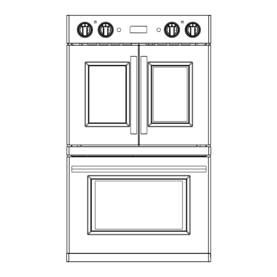
Product Contents FBOEL1333-30 FBOEL1340-30 FBOEL1340-30 FBOEL1333-30 Oven control knob Oven indicator (Upper oven ) Oven indicator Oven control knob (Upper oven ) Temperature control knob Digital Display (Upper oven ) Oven light push button Oven light push button (Upper oven ) - Page 8 Product Contents (continued) Supplied Parts For FBOEL1388-30 4x Baking rack 1x Baking Pan 1x Air Fryer Rack 1x Air Fry Basket 3x Forno Door Handle Double wall oven Supplied Parts For FBOEL1371-30 4x Baking rack 1x Baking Pan 1x Air Fryer Rack...
-
Page 9: Package Contents
1. Remove all packing material. 2. Make sure all accessories are present. Contact customer support for damaged or missing parts at 1-866-231-8893 or email info@forno.ca. Door handle installation The door handle is not pre-installed. To install the handles, you can refer to the diagram below which will show you how to install step-by-step. -
Page 10: Oven Rack Installation
Door handle installation (continued) Chef Door: Only for FBOEL1340-30: Lower oven Step 2: Step 1: To reach the embedded screw, insert the screwdriver Open the oven door and remove the 2x black rubber into the hole and push the screw forward until the caps located at the back of the oven door. -
Page 11: Electrical Requirement
Performance may be compromised if the electrical supply is less than 240 volts. The oven is supplied with a conduit consisting of two insulated hot lead conductors and a bare ground conductor. The wiring diagram covering the control circuit is provided with the oven. Electrical Requirement- FBOEL1333-30 (Single Oven) Electrical Supply Grounded, 240 VAC, 60Hz... -
Page 12: Product Dimension
Product Dimension FBOEL1340-30 FBOEL1333-30... - Page 13 The bracing should be 2” (5 cm) minimum width to support the oven side rails. Standard 2” x 4” (5 cm x 10 cm) studs are recommended. FBOEL1340-30 FBOEL1333-30 1. Base must be capable of supporting 1. Base must be capable of supporting 330 pounds (150 kg).
- Page 14 Product Dimension (continued) WARNING Do not remove spacers (if equipped) on the side walls of the built-in oven. These spacers center the oven in the space provided. The oven must be centered to prevent excess heat buildup that may result in heat damage or fire. FBOEL1340-30 30 1/8”...
- Page 15 Do not remove spacers (if equipped) on the side walls of the built-in oven. These spacers center the oven in the space provided. The oven must be centered to prevent excess heat buildup that may result in heat damage or fire. FBOEL1333-30 25 ⁵/16”...
-
Page 16: Installation Instruction
Installation Instruction IMPORTANT: This appliance shall be installed only by authorized persons and in accordance with the manufacturer’s installation instructions, municipal building codes, electrical wiring regulations. IT IS RECOMMENDED TO HAVE AT LEAST 2 PEOPLE TO ASSIST WITH THE INSTALLATION PROCESS. TO INSTALL YOUR WALL OVEN, FOLLOW THESE STEPS CAREFULLY: Step 1: Note: Do not use the handle or any portion of the front frame for lifting. - Page 17 Installation Instruction (continued) STEP 4: Make electrical connection WARNING Electrical Shock Hazard Grounding through the neutral conductor is prohibited for new branch-circuit installations (1996 NEC); mobile homes; and recreational vehicles, or in an area where local codes prohibit grounding through the neutral conductor. For instal- lations where grounding through the neutral conductor is prohibited, see the Ungrounded Neutral graphic.
- Page 18 Installation Instruction (continued) Ungrounded Neutral Junction Box Black Wires Red Wires Cable from Oven UL listed or CSA Approved Conduit Connector Ground (Green or Bare) Wire UL Listed Wire Connectors Neutral (White)Wires House Electrical Supply 1. Disconnect power 2. Connect the 2 black wires b together using a UL listed wire connector. 3.
-
Page 19: Operating Instructions
Installation Instruction (continued) STEP 6: Replace the door (if necessary) IMPORTANT: The oven door is heavy and fragile, and the door front is glass. To avoid oven door glass breakage, use both hands, and grasp only the sides of the oven door to remove. 1. - Page 20 Operating Instructions (continued) Bake Baking is cooking with heated air. Follow the recipe or convenience food directions for baking temperature, time and rack position. Baking time will vary with the temperature of ingredients and the size, shape and finish of the bakeware. 1.
- Page 21 Operating Instructions (continued) Clean Use the Clean mode to clean the oven interior regularly. The working temperature is 500°F, and the working time is 1 hour. No need to remove the baking racks. Any soil is burned off by the intense heat. 1.
-
Page 22: Care And Maintenance
Operating Instructions (continued) pressing the UP or DOWN buttons (01-12), when done, press the CLOCK and repeat the steps for the minutes (00-59). To confirm the setting simply press the CLOCK again or wait approximately 5 seconds. Other Function: 1. Press and hold on the UP or DOWN button can speed up the setting. 2. -
Page 23: Wire Diagram
Wire Diagram... - Page 24 Wire Diagram...
-
Page 25: Warranty
Retain proof of original purchase to establish warranty • Replacement of parts/service calls due to wear and tear period. Forno’s liability on any claim of any kind, with respect of components such as seals, knobs, pan supports, to the goods and/or services provided, shall in no event... - Page 26 TO PURCHASER AND PURCHASER’S PROPERTY AND TO OTHERS AND THEIR PROPERTY ARISING FROM THE USE, MISUSE, OR INABILITY TO USE THIS PRODUCT SOLD BY FORNO THAT IS NOT A DIRECT RESULT OF NEGLIGENCE ON THE PART OF FORNO THIS LIMITED WARRANTY SHALL NOT EXTEND TO ANYONE OTHER THAN THE ORIGINAL PURCHASER OF THIS PRODUCT, IS NON-TRANSFERABLE, AND STATES YOUR EXCLUSIVE REMEDY.
- Page 27 FBOEL1333-30 FBOEL1340-30 FOURS MURAUX SIMPLES OU DOUBLES NUMÉRO DE MODÈLE SÉRIE : FBOEL1333-30 | FBOEL1340-30 MANUEL D'INSTRUCTION ET GUIDE D'INSTALLATION 5015011 Conforms to UL STD 858 & CSA / ANSI STD Z21.1 Certified to CSA STDs C22.2#61 & CSA STD 1.1 Lisez attentivement ces instructions avant d'utiliser votre appareil et conservez-les soigneusement.
- Page 28 TABLE DES MATIÈRES Service clientèle Sécurité Contenu du produit Contenu du paquet Installation de la poignée de porte Installation des grilles de four Exigences électriques Dimension du produit Instructions d'installation Instructions d'utilisation Entretien et maintenance Dépannage Schéma de câblage Garantie...
- Page 29 FOURS MURAUX SIMPLES OU DOUBLES FBOEL1333-30 FBOEL1340-30 NUMÉRO DE MODÈLE SÉRIE : FBOEL1333-30 | FBOEL1340-30...
-
Page 30: Service Clientèle
Toute intervention sous garantie doit être autorisée par le service clientèle de FORNO. Tous nos prestataires de services agréés sont soigneusement sélectionnés et rigoureusement formés par nos soins. -
Page 31: Sécurité
Sécurité Votre sécurité et celle des autres sont très importantes. De nombreux messages de sécurité importants figurent dans ce manuel et sur votre appareil. Lisez et respectez toujours tous les messages de sécurité. Il s'agit d'un symbole d'alerte de sécurité. Il vous avertit des risques potentiels pour la sécurité des personnes et des biens. - Page 32 Sécurité (suite) suffisamment chaudes pour provoquer des brûlures. Les surfaces potentiellement chaudes comprennent l'ouverture de l'évent du four, les surfaces proches de l'ouverture, les crevasses autour de la porte du four, les pièces métalliques au-dessus de la porte, toute protection arrière ou surface d'étagère élevée. 10.
-
Page 33: Contenu Du Produit
Contenu du produit FBOEL1333-30 FBOEL1340-30 FBOEL1340-30 FBOEL1333-30 Bouton de commande du four Indicateur de four (Four supérieur) Indicateur de four Bouton de commande du four (Four supérieur) Bouton de contrôle de la température Affichage numérique (Four supérieur) Bouton-poussoir de l'éclairage Bouton-poussoir de l'éclairage... - Page 34 FBOEL1340-30 4x Grille de cuisson 1x moule à pâtisserie 1x support pour friteuse 1x Panier à friture à air 3x Poignée de porte Forno Four à double paroi Pièces fournies pour FBOEL1333-30 2x Grille de cuisson 1x moule à pâtisserie 1x support pour friteuse 1x Panier à...
-
Page 35: Contenu Du Paquet
1. Retirer tous les matériaux d'emballage. 2. Assurez-vous que tous les accessoires sont présents. Contactez le service clientèle pour les pièces endommagées ou manquantes au 1-866-231-8893 ou envoyez un courriel à info@forno.ca. Installation de la poignée de porte La poignée de porte n'est pas préinstallée. Pour installer les poignées, vous pouvez vous référer au diagramme ci-des- sous qui vous montrera comment les installer étape par étape. - Page 36 Installation de la poignée de porte (suite) Porte Chef : Uniquement pour FBOEL1340-30 : Four Étape 2 : inférieur Pour atteindre la vis encastrée, insérez le tournevis dans Étape 1 : le trou et poussez la vis vers l'avant jusqu'à ce que le Ouvrez la porte du four et retirez les deux capuchons filetage apparaisse de l'autre côté.
-
Page 37: Exigences Électriques
Le schéma de câblage du circuit de commande est fourni avec le four. Exigences électriques - FBOEL1333-30 (four simple) Fourniture d'électricité Mise à la terre, 240 VAC, 60Hz Service circuit dédié... -
Page 38: Dimension Du Produit
Dimension du produit FBOEL1340-30 FBOEL1333-30... - Page 39 être plats et de niveau. Le renfort doit être d'une largeur minimale de 5 cm (2") pour soutenir les rails latéraux du four. Il est recommandé d'utiliser des montants standard de 5 cm x 10 cm (2" x 4"). FBOEL1340-30 FBOEL1333-30 1. La base doit pouvoir supporter 330 1. La base doit pouvoir supporter 200 livres (150 kg).
- Page 40 Dimension du produit (suite) AVERTISSEMENT Ne retirez pas les entretoises (le cas échéant) sur les parois latérales du four encastré. Ces entretoises permettent de centrer le four dans l'espace prévu à cet effet. Le four doit être centré afin d'éviter toute accumulation de chaleur excessive susceptible d'entraîner des dommages ou un incendie.
- Page 41 Ne retirez pas les entretoises (le cas échéant) sur les parois latérales du four encastré. Ces entretoises permettent de centrer le four dans l'espace prévu à cet effet. Le four doit être centré afin d'éviter toute accumulation de chaleur excessive susceptible d'entraîner des dommages ou un incendie. FBOEL1333-30 25 ⁵/16” 24”...
-
Page 42: Instructions D'installation
Instructions d'installation IMPORTANT : Cet appareil ne doit être installé que par des personnes autorisées et conformément aux instructions d'in- stallation du fabricant, aux codes de construction municipaux et aux réglementations en matière de câblage électrique. IL EST RECOMMANDÉ D'AVOIR AU MOINS DEUX PERSONNES POUR AIDER AU PROCESSUS D'INSTALLATION. - Page 43 Instructions d'installation (suite) ÉTAPE 4 : Effectuer la connexion électrique AVERTISSEMENT Risque de choc électrique La mise à la terre par le conducteur neutre est interdite pour les nouvelles installations de circuits de dérivation (NEC 1996), les maisons mobiles et les véhicules de loisirs, ou dans une zone où les codes locaux interdisent la mise à la terre par le conducteur neutre.
- Page 44 Instructions d'installation (suite) Ungrounded Neutral Boîte de jonction Fils noirs Fils rouges Câble du four Connecteur de conduit homo- logué UL ou CSA Fil de terre (vert ou nu) Connecteurs de fils homo- logués UL Fils neutres (blancs) Fourniture d'électricité à domicile 1.
-
Page 45: Instructions D'utilisation
Instructions d'installation (suite) ÉTAPE 6 : Remettre la porte en place (si nécessaire) IMPORTANT : La porte du four est lourde et fragile, et la façade de la porte est en verre. Pour éviter de briser la vitre de la porte du four, utilisez vos deux mains et ne saisissez que les côtés de la porte du four pour la retirer. - Page 46 Mode d'emploi (suite) Cuisson La cuisson est une cuisson à l'air chaud. Suivez les instructions de la recette ou du produit alimentaire pour la température de cuisson, le temps et la position de la grille. Le temps de cuisson varie en fonction de la température des ingrédients et de la taille, de la forme et de la finition du moule.
- Page 47 Mode d'emploi (suite) Nettoyer Utilisez le mode Clean pour nettoyer régulièrement l'intérieur du four. La température de travail est de 500°F et le temps de travail est de 1 heure. Il n'est pas nécessaire de retirer les grilles de cuisson. Le sol est brûlé par la chaleur intense. 1.
-
Page 48: Entretien Et Maintenance
Mode d'emploi (suite) Horloge Appuyez sur la touche CLOCK pendant environ 3 secondes pour accéder au réglage. L'écran affiche 12:00. Réglez l'heure en appuyant sur les boutons UP ou DOWN (01-12), puis appuyez sur CLOCK et répétez les étapes pour les minutes (00-59). -
Page 49: Schéma De Câblage
Schéma de câblage... - Page 50 Schéma de câblage...
-
Page 51: Garantie
Garantie Ce que couvre cette garantie limitée : • L'utilisation du produit dans une application commerciale La couverture de la garantie fournie par Forno Appliances dans non résidentielle. cette déclaration s'applique exclusivement à l'appareil Forno • L'utilisation du produit à d'autres fins que celles prévues. - Page 52 CONSÉCUTIF CAUSÉ PAR L'UTILISATION, LA MAUVAISE UTILISATION OU L'INCAPACITÉ D'UTILISER CE PRODUIT, QUELLE QUE SOIT LA THÉORIE JURIDIQUE SUR LAQUELLE REPOSE LA RÉCLAMATION, ET MÊME SI FORNO A ÉTÉ INFORMÉE DE LA POSSIBILITÉ DE TELS DOMMAGES. DE MÊME, LE MONTANT DE TOUT RECOUVREMENT À L'ENCONTRE DE FORNO NE POURRA ÊTRE SUPÉRIEUR AU PRIX D'ACHAT DU PRODUIT VENDU PAR FORNO ET À...
- Page 53 FBOEL1333-30 FBOEL1340-30 HORNOS DE PARED SIMPLES O DOBLES NÚMERO DE MODELO SERIE: FBOEL1333-30 | FBOEL1340-30 MANUAL DE INSTRUCCIONES Y GUÍA DE INSTALACIÓN 5015011 Conforms to UL STD 858 & CSA / ANSI STD Z21.1 Certified to CSA STDs C22.2#61 & CSA STD 1.1 Lea atentamente estas instrucciones antes de utilizar el aparato y guárdelas cuidadosamente.
- Page 54 ÍNDICE DE CONTENIDOS Atención al cliente Seguridad Contenido del producto Contenido del paquete Instalación del tirador de la puerta Instalación de la rejilla del horno Requisitos eléctricos Dimensiones del producto Instrucciones de instalación Instrucciones de uso Cuidado y mantenimiento Solución de problemas Diagrama de cableado Garantía...
- Page 55 HORNOS DE PARED SIMPLES O DOBLES FBOEL1333-30 FBOEL1340-30 NÚMERO DE MODELO SERIE: FBOEL1333-30 | FBOEL1340-30...
-
Page 56: Atención Al Cliente
Si no entiende algo o necesita más ayuda, visite nuestro sitio web o envíe un correo electrónico a: info@forno.ca Si hay algún problema, póngase en contacto con el servicio de atención al cliente de FORNO. Tenga en cuenta que antes de poder enviar a un proveedor de servicios será... -
Page 57: Seguridad
Seguridad Tu seguridad y la de los demás son muy importantes. Hemos incluido muchos mensajes de seguridad importantes en este manual y en su aparato. Lea y obedezca siempre todos los mensajes de seguridad. Se trata de un símbolo de alerta de seguridad. Le alertará de posibles peligros para la seguridad personal o de la propiedad. - Page 58 Seguridad (continuación) superficies potencialmente calientes incluyen la abertura de ventilación del horno, las superficies cercanas a la aber- tura, las hendiduras alrededor de la puerta del horno, las piezas de adorno metálicas encima de la puerta, cualquier protección trasera o superficie alta del estante. 10.
-
Page 59: Contenido Del Producto
Contenido del producto FBOEL1333-30 FBOEL1340-30 FBOEL1340-30 FBOEL1333-30 Perilla de control del horno Indicador del horno (Horno superior ) Indicador del horno Perilla de control del horno (Horno superior ) Perilla de control de Pantalla digital temperatura (Horno superior ) Pulsador de la luz del horno... - Page 60 Piezas suministradas para FBOEL1340-30 4x Rejilla para hornear 1x Molde 1x Rejilla para freidora 1x Cesta para freír 3x Manilla de puerta Forno Horno mural doble Piezas suministradas para FBOEL1333-30 2x rejilla para hornear 1x Molde 1x Rejilla para freidora 1x Cesta para freír...
-
Page 61: Contenido Del Paquete
2. Asegúrese de que están todos los accesorios. Póngase en contacto con el servicio de atención al cliente en caso de piezas dañadas o faltantes llamando al 1-866-231- 8893 o enviando un correo electrónico a info@forno.ca. Instalación del tirador de la puerta El tirador de la puerta no está... -
Page 62: Instalación De La Rejilla Del Horno
Instalación del tirador de la puerta (continuación) Puerta Chef: Sólo para FBOEL1340-30: Horno inferior Segundo paso: Primer paso: Para alcanzar el tornillo incrustado, introduzca el Abra la puerta del horno y retire las 2 tapas de goma destornillador en el orificio y empuje el tornillo hacia negras situadas en la parte posterior de la puerta del delante hasta que aparezcan las roscas en el otro lado. -
Page 63: Requisitos Eléctricos
El diagrama de cableado que cubre el circuito de control se suministra con el horno. Requisitos eléctricos- FBOEL1333-30 (Horno individual) Conexión a tierra, 240 VCA, 60 Suministro eléctrico... -
Page 64: Dimensiones Del Producto
Dimensiones del producto FBOEL1340-30 FBOEL1333-30... - Page 65 5 cm (2") para soportar los rieles laterales del horno. Se recomiendan tacos estándar de 5 cm x 10 cm. FBOEL1340-30 FBOEL1333-30 1. La base debe poder soportar 150 kg 1. La base debe poder soportar 90 kg (330 libras).
- Page 66 Dimensiones del producto (continuación) ADVERTENCIA No retire los espaciadores (si los hay) de las paredes laterales del horno empotrado. Estos espaciadores centran el horno en el espacio previsto. El horno debe estar centrado para evitar una acumulación excesiva de calor que pueda provocar daños térmicos o un incendio.
- Page 67 No retire los espaciadores (si los hay) de las paredes laterales del horno empotrado. Estos espaciadores centran el horno en el espacio previsto. El horno debe estar centrado para evitar una acumulación excesiva de calor que pueda provocar daños térmicos o un incendio. FBOEL1333-30 25 ⁵/16” 24”...
-
Page 68: Instrucciones De Instalación
Instrucciones de instalación IMPORTANTE: Este aparato debe ser instalado únicamente por personal autorizado y de acuerdo con las instrucciones de instalación del fabricante, los códigos de construcción municipales y las normas de cableado eléctrico. SE RECOMIENDA CONTAR CON AL MENOS 2 PERSONAS PARA AYUDAR EN EL PROCESO DE INSTALACIÓN. - Page 69 Instrucciones de instalación (continuación) PASO 4: Realice la conexión eléctrica ADVERTENCIA Peligro de descarga eléctrica La conexión a tierra a través del conductor neutro está prohibida para las nuevas instalaciones de circuitos derivados (NEC 1996); casas móviles; y vehículos recreativos, o en un área donde los códigos locales prohíben la conexión a tierra a través del conductor neutro.
- Page 70 Instrucciones de instalación (continuación) Ungrounded Neutral Caja de empalmes Cables negros Cables rojos Cable del horno Conector de conducto ho- mologado por UL o CSA Cable de tierra (verde o desnudo) Conectores de cable con certificación UL Cables neutros (blancos) Suministro eléctrico domésti- 1.
-
Page 71: Instrucciones De Uso
Instrucciones de instalación (continuación) PASO 6: Vuelva a colocar la puerta (si es necesario) IMPORTANTE: La puerta del horno es pesada y frágil, y el frontal de la puerta es de cristal. Para evitar la rotura del cristal de la puerta del horno, utilice ambas manos y agarre sólo los laterales de la puerta del horno para retirarla. 1. - Page 72 Instrucciones de uso (continuación) Hornear Hornear es cocinar con aire caliente. Siga las instrucciones de la receta o del alimento precocinado en cuanto a temperatura de horneado, tiempo y posición de la rejilla. El tiempo de horneado variará en función de la temperatura de los ingredientes y del tamaño, la forma y el acabado del molde.
- Page 73 Instrucciones de uso (continuación) Limpia Utilice el modo Limpiar para limpiar el interior del horno con regularidad. La temperatura de trabajo es de 500°F, y el tiempo de trabajo es de 1 hora. No es necesario retirar las rejillas de horneado. El intenso calor quema la tierra. 1.
-
Page 74: Cuidado Y Mantenimiento
Instrucciones de uso (continuación) Reloj Pulse el RELOJ durante aproximadamente 3 segundos para entrar en el ajuste. La pantalla mostrará las 12:00. Ajuste la hora pulsando los botones ARRIBA o ABAJO (01-12), cuando termine, pulse el RELOJ y repita los pasos para los minutos (00-59). -
Page 75: Diagrama De Cableado
Diagrama de cableado... - Page 76 Diagrama de cableado...
-
Page 77: Garantía
El Comprador debe inspeccionar el producto en el momento • Sustitución de piezas/reclamaciones de servicio por falta de la entrega. Forno garantiza que el Producto está libre de de mantenimiento o mantenimiento inadecuado, incluidos, defectos de fabricación en materiales y mano de obra durante entre otros: acumulación de residuos, manchas, arañazos,... - Page 78 Y RESPONSABILIDAD POR PÉRDIDAS, DAÑOS O LESIONES AL COMPRADOR Y A LA PROPIEDAD DEL COMPRADOR Y A OTROS Y A SU PROPIEDAD QUE SURJAN DEL USO, MAL USO O INCAPACIDAD DE USO DE ESTE PRODUCTO VENDIDO POR FORNO QUE NO SEA RESULTADO DIRECTO DE NEGLIGENCIA POR PARTE DE FORNO ESTA GARANTÍA LIMITADA NO SE EXTENDERÁ...
- Page 80 Atención al cliente: Llame al 1-866-231-8893 o envíe un correo electrónico: info@forno.ca...
Need help?
Do you have a question about the FBOEL1333-30 and is the answer not in the manual?
Questions and answers