
Related Manuals for Axis 2 Series


Summary of Contents for Axis 2 Series
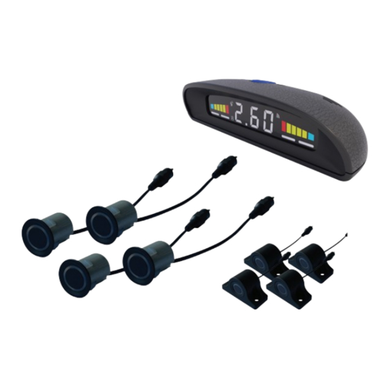
- Page 5 tection range and warning method 0. 30 0.00 0.00 1.10 1.ll 1.00 2.10 2.00 Distance (m) R8"" centre 0. 30~2. 60 Distance ....display ReY Sides 0 .30~2.10 1 ,4 ..
- Page 6 Fix the plsition of sensors. No obstacle should be detected at 90° from the top view otherwise the system will false alarm. Installation distance dragram Best position for 4 sensors Installation diagram for sensors with direction markings Installation diagram Installation when bumper is sloping to the ground.
- Page 7 Smooth slope Smooth round objects Objects sbsorbing wave,e.g.cotton Objects hard to be detected ADVISED POSITION TO INSTALL THE SENSOR A. Four drill holes A.B.C.D should be in line. B. 0.5~0.8m vertical to the ground. 0.55m is recommended. C. Vertical, tidy surface without metal components is preferred.
- Page 8 SELECT DRILLING POSITION FOR SENSOR A&D A. Choose suitable drilling positions for A and D sensor and mark. For best detection angle, position A & D sensor 1/8 from the edge. SELECT DRILLING POSITION FOR SENSOR B&C A. Measure the distance between sensor A and D.
- Page 9 S-59 Sensor Assembly and Install S-59 Sensor Assembly and Installation...
-
Page 11: Troubleshooting
TROUBLE SHOOTING Problem Cause Remedy Displays no reading a. Poor ground connection a. Properly ground black wire when reversing b. No signal b. Move the module to a location c. The fuse is blown. with fewer obstructions c. Replace with same size fuse Monitor constantly An object protruding from Adjust the minimum detection...
Need help?
Do you have a question about the 2 Series and is the answer not in the manual?
Questions and answers