Advertisement
Quick Links
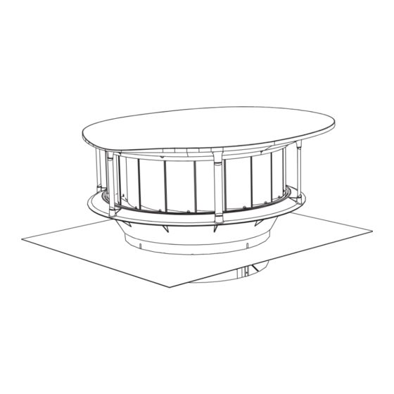
Installation Manual
This installation is for the:
Odyssey HR2400 Series Ventilation System
.
T
his installation is limited to roofs with pitches between 3° and 35°.
This instruction assumes that there is a power outlet located within reach of the Odyssey system in the roof. If there is no power
outlet within reach then the installation of a power outlet must be carried out by a licenced electrician.
Exhaust fans may adversely affect the safe operation of appliances burning gas or other fuels (including those in other rooms) due
to back flow of combustion gases. These gases can potentially result in carbon monoxide poisoning. After installation of an
exhaust fan such as a partition fan or a duct fan the operation of open flued gas appliances should be tested by a competent
person to ensure that back flow of combustion gases does not occcur.
Advertisement

Related Manuals for Bradford Odyssey H2400


Summary of Contents for Bradford Odyssey H2400
- Page 1 Installation Manual This installation is for the: Odyssey HR2400 Series Ventilation System his installation is limited to roofs with pitches between 3° and 35°. This instruction assumes that there is a power outlet located within reach of the Odyssey system in the roof. If there is no power outlet within reach then the installation of a power outlet must be carried out by a licenced electrician.
- Page 2 Item Checklist & Additional Tools Required For Installation Included Parts: Qty: Ventilator Valve/Controller/Ducting Grille LCD User Interface Panel LCD Panel Cable Temperature Sensors Temperature Sensor Cables Mains Power Cable Duct tape Roll Tek Screws CSK Screws Installation Manual Operations Manual Warranty Document Additional Parts &...
- Page 4 Warnings and Important Notices WARNING: Do not proceed with the installation until you have read the entire instructions, including these warnings. INSTALL AT YOUR OWN RISK The installation of this product may be dangerous and includes the potential of death, personal injury or property damage. Please be aware of the following before installing this product.
-
Page 5: Warnings And Important Notices
Warnings and Important Notices • Be careful to determine that the eave into which the sensor is being installed does not contain Asbestos. If it is or you cannot determine make up, then the sensor can only be installed using asbestos handling procedures by a person trained and/or licensed to handle asbestos. - Page 6 Installation - Tiled Roof STEP 1 Select a suitable position for the ventilator on the roof no higher than the third row of tiles down from the ridge, keeping in mind that the ceiling grille needs to be installed in the ceiling almost directly below.
- Page 7 Installation - Tiled Roof STEP 3 Remove any complete Cut Tiles as required tiles as required and also cut parts of tiles to enable the collar to pass through the roof. STEP 4 Cut & remove a section of tile batten to clear the ducting collar as shown.
- Page 8 Installation - Tiled Roof STEP 5 Fit the ventilator into place and ensure surrounding tiles are fitted securely. Note that the longer side of the rain cowl/ cover should be pointing towards the ridge of the roof. Take care to ensure the ventilator cables are passed through safely down towards the lower side and not caught on any sharp edges.
- Page 9 Installation - Tiled Roof STEP 7 To ensure a weatherproof installation, apply a bead of silicone between the tiles and the side and front edges of the flashing. STEP 8 Batten From within the roof space, pull the aluminium fixing strap that is attached to the ducting collar across to the batten near the bottom side.
- Page 10 Installation - Metal Roof STEP 9 Select a suitable position for the ventilator, keeping in mind that the ceiling grille needs to be installed in the ceiling almost directly below. It is also recommended that the ceiling grille be installed somewhere near the centre of the building, away from windows or other openings.
- Page 11 Installation - Metal Roof STEP 11 Turn up the corrugations Turn Up or pans on both the low and high sides. Turn Up STEP 12 Place ventilator into position and temporarily fix with 4 Tek screws.
- Page 12 Installation - Metal Roof STEP 13 Using a soft rubber hammer, carefully form the flashing into the corrugations of the metal sheet profile at the lower edge and sides. STEP 14 Remove screws and lift flashing to run a bead of silicone along the underside of the flashing along the lower and side...
- Page 13 Installation - Metal Roof STEP 15 Secure the flashing to roof sheeting with at least 13 Tek screws or sealed rivets along the lower and sides edges shown. Additionally fix 4 Tek screws or sealed rivets evenly spaced around the opening.
- Page 14 Valve, Ducting & Grille Installation STEP 16 Locate the round top edge of the valve into the collar, ensuring that the 4 pins locate into the bayonet slots. Push the valve up to the top then rotate clockwise to lock the bayonet. Ensure that the controller is facing towards the low end of the roof and that the cables are routed through the cable slot.
- Page 15 Valve, Ducting & Grille Installation STEP 18 Take the pre-fixed flexible strap and pull Screw to Batten taut to suitable batten, fixing it with a screw. Strap If tightening is required unscrew strap at valve side, tighten strap and refix screw. Ensure strap is securely fixed to the valve casing.
- Page 16 Valve, Ducting & Grille Installation STEP 20 Cut the ducting to length so that approximately 100 of ducting can hang down past the ceiling level. Approximately Ceiling 100mm of Extra Ducting Length STEP 21 Locate position for ceiling grille from under ceiling and using the supplied template, mark out the shape to...
- Page 17 Valve, Ducting & Grille Installation STEP 22 Fix With Tape Drop the ducting down through the cut out so that it hangs down approximately 100 Slide the collar of the ceiling grille frame half way into the ducting. Secure the ducting to the collar using supplied duct tape.
- Page 18 Valve, Ducting & Grille Installation STEP 24 Fit the ceiling grille to the ceiling grille frame. The ceiling grille is held in place by magnets and must be fitted so that it aligns with notches in the frame. The grille can be rotated until it fits into these notches and then the magnets should securely hold it in place.
- Page 19 Temperature sensor and User Interface Panel Installation Note: One temperature sensor needs to be installed on an internal ceiling and one externally under an eave. Two identical temperature sensors are supplied for this purpose. STEP 25 Select an eave on a side of the building that does not receive direct sunlight for the position of the exter-...
- Page 20 Temperature sensor and User Interface Panel Installation STEP 27 Using the two screws supplied, fix the sensor to the eave through two of the three holes in the sensor base plate. STEP 28 Clip the cover plate over the sensor base plate.
- Page 21 Temperature sensor and User Interface Panel Installation STEP 29 For the living space temperature sensor, select a position on an internal ceiling that is not exposed to direct sunlight and is representative of the 25mm Hole internal house temperature. Ensure that the position selected will allow the sensor to reach and connect to the controller with the supplied 10 long cable.
- Page 22 Temperature sensor and User Interface Panel Installation STEP 31 Select a position on an interior wall for installing the user interface panel. The panel should be placed at a height to allow easy reading of the screen. Preferrably the panel should be placed either at or below eye level. Ensure there are no cables or pipes in the way before cutting.
- Page 23 Temperature sensor and User Interface Panel Installation STEP 33 Detach the wall mounting plate from the LCD Module. Fix it to the wall using 2 screws. Fix these diagonally opposite. STEP 34 Take the LCD screen cable and either run it up the wall cavity to the controller, or run it down the cavity from the...
- Page 24 Temperature sensor and User Interface Panel Installation STEP 35 Clip the LCD module into the wall mounting plate. STEP 36 Carefully peel the protective film from the screen and clip the front cover panel into place.
- Page 25 Controller Connections Details Connect the Ventilator, Sensor and LCD UI Cables to the controller as specified in the diagram below. The Valve Control Cable should be pre-connected from the factory. Take care to ensure that the living space and external sensors are connected to the correct sockets. 4 5 6 7 240VAC Power In Ventilator Power Cable...
- Page 26 Technical Data Material: Ventilator: Plastic (ASA & PPS-GF40) Valve: Plastic (ASA & PA6-GF30) Grille: Plastic (ASA) UI Panel: Plastic (ASA) Temperature Sensor: Plastic (ASA) Controller: Plastic (PC-V0) Weight: Ventilator: 9.21 kg Valve: 2.97 kg Grille: 1.06 kg Electrical: Input: 220-240VAC 50Hz Max:55W...
- Page 27 Product Dimensions Ventilator...
- Page 28 Product Dimensions Valve & Controller 398.3...
- Page 29 Product Dimensions Ceiling Grille 53.7...
-
Page 30: Product Dimensions
Product Dimensions User Interface Panel User Interface Panel 12.25 53.7 50.5 17.7 Temperature Sensor Temperature Sensor 47.4... -
Page 31: Contact Details
General Enquiries and Support 1300 760 233 sales@csr.com.au Email: Technical Ventilation Enquiries 1800 354 044 October 2019 I-041-B Bradford is a business division of CSR Building Products Limited ABN 55 008 631 356 10 Stanton Road, Seven Hills NSW 2147 Australia | www.bradfordventilation.com.au... - Page 32 bradfordventilation.com.au...
Need help?
Do you have a question about the Odyssey H2400 and is the answer not in the manual?
Questions and answers