Advertisement
Quick Links
Advertisement

Related Manuals for FLIGHTORY STALLION VTOL


Summary of Contents for FLIGHTORY STALLION VTOL
- Page 1 VTOL USER MANUAL © 2023 Flightory by Szymon Wójcik All rights reserved. USER MANUAL...
- Page 2 Socials Join Flightory Tech group on Facebook and create community with us. Share progress of your builds. Any suggestions or questions welcome. www.facebook.com/groups/flightory Follow Instagram where I share more footage on a regular basis www.instagram.com/flightory_ USER MANUAL...
- Page 3 General Aircraft Data The build of this aircraft requires owning the basic version of the Stallion. Modification for VTOL requires reprinting the wings along with all motor mounting components. This instruction manual presents conversion to VTOL version. If you are starting to build the aircraft from scratch, refer to the manual for the regular Stallion, which details the construction of the entire aircraft.
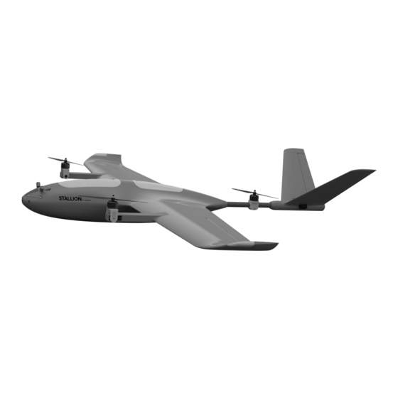
- Page 4 General Aircraft Data The aircraft is in the classic trimotor configuration with front tilt motors and one rear fixed motor. Yaw in hover mode is controlled by tilting the front motors. The rest of the aircraft's geometry remains unchanged from the regular Stallion version.
- Page 5 PARTS LIST - VTOL PART MATERIAL BOOM L /R PETG MOTOR MOUNT FRONT PETG MOTOR MOUNT TAIL PETG WING 1 L/R VTOL LW-PLA WING 2 L/R VTOL LW-PLA WING 3 L/R VTOL LW-PLA If you have access to a printer capable of printing at high temperatures around 300°C you may also consider printing with materials containing carbon fiber additives instead of regular PETG, which will further reinforce the components.
- Page 6 Reccomended Accessories and RC Equipment Reccomended electronics Motors Emax ECOII 2807 1300KV link / T- Motor F90 1300KV link Propellers 7x4 / 7x5 / 7x6 (two CCW, one CW) link Servos 2pcs PowerHD 1810MG link / GDW DS041MG link 3pcs Emax Formula Series 45A BLHeli32 link / Lumenier 51A link...
- Page 7 Parts Orientation WING 1 L/R VTOL - 3% cubic subdivision infill WING 2 L/R VTOL - 3% cubic subdivision infill USER MANUAL...
- Page 8 Parts Orientation BOOM L/R – 3 walls, 20% cubic infill MOTOR MOUNT TAIL 3 walls, 20% cubic infill USER MANUAL...
- Page 9 Parts Orientation MOTOR MOUNT FRONT- 100% infill solid print This component is particularly exposed to loads and vibrations. It requires printing with full infill. Additionally, I recommend reinforcing this part further. A simple and quick way is to acquire a small sheet of thin fiberglass cloth and a small amount of epoxy resin.
- Page 10 STL AND STEP FILES All files in VTOL PACK are available in STL and STEP format. You can find these files in folders labeled STEP USER MANUAL...
- Page 11 Tail Motor Assembly 195mm To mount the tail motor, you'll need to remove the tail boom. The correct positioning of the motor is as shown in the diagram. The motor shaft should be located 195mm from the front end of the tube. USER MANUAL...
- Page 12 Tail Motor Assembly Take the MOTOR MOUNT TAIL and screw the motor onto it. To mount it, you slide it onto the tailboom. Press the M3 threaded insert from one side and insert the M3 screw from the other side. Align the motor properly and tighten the mount on the tail boom to make it stiff and immobile.
- Page 13 Tail Motor Assembly You can now slide the tail boom into the fuselage and secure it with the M3 screw as usual. USER MANUAL...
- Page 14 Front Boom Assembly To start, screw the motor onto the MOTOR MOUNT FRONT. At this stage, also screw in the M3 screw from the inside of the BOOM as shown in the drawing. Secure it tightly with a nut from the outside. Finally, place a washer. The screw should be about 15mm long.
- Page 15 Front Boom Assembly Next, insert the servo into the designated slot and secure it with the small screws that should be included in the servo package. Route the cables through the channel running underneath. USER MANUAL...
- Page 16 Front Boom Assembly Now, place the motor in the manner shown in the drawing. Insert the servo horn, which secures the assembly from one side. Route the motor cables directly into the lower channel. USER MANUAL...
- Page 17 Front Boom Assembly Now, on the other side, insert the 3x8x4mm bearing and finally secure it with an M3 nut. This ultimately stabilizes the mounting and ensures smooth movement. USER MANUAL...
-
Page 18: Wing Assembly
Wing Assembly Now, assemble the entire wing. The assembly process is almost identical to the basic version of the Stallion. Only segments 1 and 2 of the wing have designated place for mounting the motor boom. Segment 3 is the same, and you can also choose whether to mount the LED or not. - Page 19 Wing Assembly After assembling the wing, firmly glue the Boom in place using CA glue, making sure to do it evenly. Note that when mounting the wing to the fuselage, the main spar will also pass through the Boom, further reinforcing the structure. USER MANUAL...
- Page 20 Wing Assembly Now insert the wings and route all the cables from the motor and servo to the channel in the wing that leads to the fuselage. Repeat the same process with the second wing. USER MANUAL...
- Page 21 Finishing Build At this stage, the entire structure is now ready, and it's time to move on to connecting cables and configuration USER MANUAL...
- Page 22 Configuration The software I recommend is Ardupilot. It's necessary to familiarize yourself with the information on the website where the full configuration of Tiltrotor Planes in Ardupilot is described. https://ardupilot.org/plane/docs/guide-tilt-rotor.html I will present here the most important information and parameters that need to be set and paid attention to.
- Page 23 Configuration Servo Output This is the assignment of all channels that you can set at the beginning. USER MANUAL...
- Page 24 Configuration MAIN TILT ROTOR PARAMETERS Q_ENABLE = 1 Next, you need to set the parameter Q_ENABLE to 1. This enables all options related to quadplane support. You need to click ‚write’ and then ‚refresh’ to obtain the full list of parameters. Q_TILT_ENABLE = 1 Also set Q_TILT_ENABLE to 1, indicating the use of tilt motors.
- Page 25 Configuration MAIN TILT ROTOR PARAMETERS Q_TILT_RATE_UP = 15 This parameter determines how quickly the motors will tilt during transition and is expressed in degrees per second. 15 degrees means that a full transition will take 6 seconds and is a good value for the Stallion, ensuring smooth transition. You can separately set Q_TILT_RATE_DN, which is the speed of tilting the motors downwards.
- Page 26 Configuration MAIN TILT ROTOR PARAMETERS ARSPD_FBW_MIN = 12 ARSPD_FBW_MAX = 25 These parameters specify the minimum and maximum speed in m/s in automatic throttle modes. The values align well with the characteristics of the Stallion. The minimum speed is crucial during transitions. Full transition will be executed upon reaching the minimum flight speed.
- Page 27 Configuration After setting all the mentioned parameters, the aircraft is ready for its first flight tests. However, I strongly encourage you to familiarize yourself with the entire chapter on quadplanes on the Ardupilot website. You will find a lot of information there regarding configuration and tuning, flight mode operations, and much more.
- Page 28 VTOL USER MANUAL...
Need help?
Do you have a question about the STALLION VTOL and is the answer not in the manual?
Questions and answers