
Related Manuals for FLIGHTORY talon 1400


Summary of Contents for FLIGHTORY talon 1400
- Page 1 USER MANUAL © 2023 Flightory by Szymon Wójcik All rights reserved. USER MANUAL...
- Page 2 Socials Join Flightory Tech group on Facebook and create community with us. Share progress of your builds. Any suggestions or questions welcome. www.facebook.com/groups/flightory Follow Instagram where I share more footage on a regular basis www.instagram.com/flightory_/ USER MANUAL...
- Page 3 General Aircraft Data General data Wingspan 1305mm Wing area 27.5 dm² Lenght 830mm Center of Gravity 65mm from leading edge 1500-3300g Optimal Cruise Speed 55-65 km/h Airfoil Eppler E205 Root Chord 240mm 211mm Aspect Ratio Wing load 54 -120 g / dm² USER MANUAL...
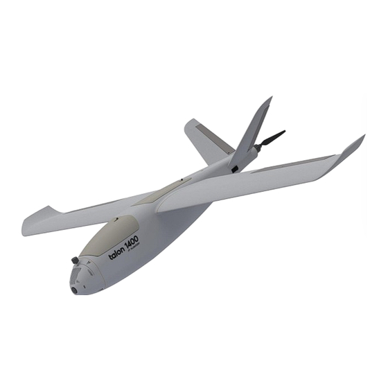
- Page 4 General Aircraft Data The aircraft is a 3D printed UAV platform in a size that combines compactness and high flight performance. Talon 1400 is in the popular layout with single push propeller. The design focuses on optimizing flight performance as possible, accommodating large battery pack and additional equipment, and modularity.
- Page 5 CFD Analysis The geometry is designed to provide the best possible characteristics. Eppler E205 airfoil was selected. The shape of the wing and the V-tail stabilizers, as well as their mutual position and incline angles, were optimized to ensure high performance as well as longitudinal stability.
-
Page 6: Exploded View
Exploded view USER MANUAL... - Page 7 Reccomended RC Equipment Reccomended electronics Motor 2830 1200KV Prop Drive / 4108 620KV Propeller 10x5 (2830 Motor) / 12x10 or 13x8 (4108 Motor) Flight Controller Speedybee F405 Wing or any other Mavlink FC Matek M10Q or similar GPS with compass Servos Corona 929MG Metal Gear or similar BlHeliS 40A...
-
Page 8: Required Accessories
Required accessories ITEM QUANTITY 10x530mm Carbon Tube (MAIN SPAR) 6x435mm Carbon Tube (SECOND SPAR) 4x190mm Carbon Tube (VTAIL SPAR) Thin CA Glue 20g tube CA Activator 1 (optional but useful) M3 Threaded Insert (Outer Ø5mm, height 5mm) M3 screw Plastic M6x45mm screw M6 nut LW-PLA 1 roll... - Page 9 PARTS LIST - FUSELAGE PART MATERIAL FUS 1 LW-PLA FUS 2 LW-PLA FUS 3 LW-PLA FUS 4 LW-PLA FUS 5 (2830 motor) LW-PLA FUS 5 (4108 motor) LW-PLA HATCH MIDDLE 1 LW-PLA HATCH MIDDLE 2 LW-PLA HATCH FRONT 1 LW-PLA HATCH FRONT 2 LW-PLA NOSE...
- Page 10 PARTS LIST - WINGS PART MATERIAL WING 1 L /R LW-PLA WING 2 L /R LW-PLA WING 3 L /R LW-PLA WINGLET L /R LW-PLA AIL L / R LW-PLA SERVO COVER (print 2) WING ROOT L /R USER MANUAL...
- Page 11 PARTS LIST - VTAIL PART MATERIAL V TAIL 1 L /R LW-PLA V TAIL 2 L /R LW-PLA V TAIL RUDDER L / R LW-PLA USER MANUAL...
-
Page 12: Print Settings
Settings are prepared a standard 0.4mm nozzle. Download link is available on Flightory Blog. Infill in this profile is set to 6%. For this project I recommend changing it to 3% for most parts. - Page 13 Print Settings All parts are suitable for printing on any standard printer with a small working area. I printed all parts on a 200 x 200mm area. The settings are just a base that you can change and adjust as needed. The following pages will list my recommended infill settings for each part.
- Page 14 Parts Orientation Important thing is the correct orientation of the printed parts to avoid overhangs, and not have to use supports. Below is the recommended orientation of parts and infill settings. FUS 1 - 3% gyroid infill FUS 2 - 3% gyroid infill USER MANUAL...
- Page 15 Parts Orientation FUS 3 - 3% gyroid infill FUS 4 - 3% gyroid infill USER MANUAL...
- Page 16 Parts Orientation FUS 5 - 3% gyroid infill NOSE - 4% gyroid infill + 2 walls USER MANUAL...
- Page 17 Parts Orientation NOSE VTX COVER- 4% gyroid infill + 2 walls HATCH FRONT 1 - 3% gyroid infill USER MANUAL...
- Page 18 Parts Orientation HATCH FRONT 2 - 3% gyroid infill HATCH MIDDLE 1 - 3% gyroid infill USER MANUAL...
- Page 19 Parts Orientation HATCH MIDDLE 2 - 3% gyroid infill WING 1 - 3% cubic subdivision infill USER MANUAL...
- Page 20 Parts Orientation WING 2 - 3% cubic subdivision infill WING 3 - 3% cubic subdivision infill USER MANUAL...
- Page 21 Parts Orientation WINGLET- 3% cubic subdivision infill AIL- 4% cubic subdivision infill USER MANUAL...
- Page 22 Parts Orientation V-TAIL 1 - 3% gyroid infill V-TAIL 2 - 3% gyroid infill USER MANUAL...
- Page 23 Parts Orientation V-TAIL RUDDER - 4% cubic subdivision infill The other parts are not shown, as they are mainly flat printed parts and their orientation is not in doubt. USER MANUAL...
- Page 24 TAIL VARIANTS Before starting build, choose an option for mounting the motor. There are 2 options to choose from. The first version is a tail adapter to the 2830 motor or other similar with a mounting bolt spacing of 34mm. Choose then the corresponding version of the FUS 5 FIREWALL...
- Page 25 NOSE VARIANTS There are also 2 variants of the nose. You can choose version with a VTX mounted inside and a 19x19mm FPV camera, or a clean version with just the FPV camera. The VTX mounts on a "shelf" and the available space is sufficient to accommodate any VTX.
- Page 26 STEP files All files are available in STL format. In addition, some important elements are available in STEP format, which allows easier editing and customization. You can find these files in folders labeled STEP USER MANUAL...
-
Page 27: Fuselage Assembly
Fuselage assembly Prepare all fuselage segments. Before gluing, you can gently sand the surface of all elements, especially the gluing surfaces. It’s best to use thick CA glue. USER MANUAL... - Page 28 Fuselage assembly Prepare parts printed from PLA or other hard material. Take the BATTERY PAD and paste it in the designated place in the front of the fuselage. It’s best to use thick CA glue. Prepare parts printed from PLA or other hard material.
- Page 29 Fuselage assembly Now take M3 threaded inserts with an outer diameter of 5mm. Glue them into the designated places in the front part of the fuselage. You can use a slightly heated soldering iron for this. Then glue NOSE REINFORCEMENT printed from PLA or other hard material.
- Page 30 Hatches Prepare the front and middle hatch. Both require LOCK 1 LOCK 2. Assemble the locks by adding a small spring and paste them into the designated places. Glue locks into the hatches using CA, but carefully so that the glue does not spill and block the lock. It’s best to use thick CA glue.
- Page 31 V-TAIL servos It’s best to use HOT GLUE Now insert the V-tail servos into the designated places on the back of the fuselage. Micro servos of standard 9-12g weight will fit. Use a small amount of hot glue to secure them. USER MANUAL...
- Page 32 V-TAIL Take V tail parts. Glue them together and use 4mm carbon tube cut to 190mm for reinforcement. Use 20x30mm polyester hinges to assemble the rudder by gluing them into the prepared places. Secure them with a drop of thin CA glue. You can also use thin hinges made of other thin materials.
- Page 33 V-TAIL Glue the plastic horns into the designated places in the rudders. It is best to do it with thick CA glue. You can make the pushrods yourself using a thin wire and bend it into a Z shape, or use snaps or another pushrod mounting technique.
-
Page 34: Motor Mount
Motor mount Paste the M3 threaded inserts into the designed places. Then glue the firewall. Finally, screw the motor with M3 screws. The graphic shows the assembly of the 2830 motor. For the 4108 motor, the process looks exactly the same, only the firewall and tail are in slightly different shape. USER MANUAL... - Page 35 Nose mount Now you can mount the nose with short M3 screws. If you are using version with VTX, you can put your VTX on the "shelf" and cover it with NOSE VTX COVER and secure the antenna. USER MANUAL...
-
Page 36: Wings Assembly
Wings assembly Glue the wing segments together. Insert two 6mm carbon tubes cut to a length of 435mm. It’s not necessary to glue the tubes, just press them tightly into the designated holes. Also insert the M6 plastic screws and glue the ROOT WING. - Page 37 Wings assembly Now mount the servo. Servo bay is spacious and there is no specific position of the servo. You can glue it and secure with hot glue. Use the SERVO COVER part so that you place it in the right place and bring the servo arm outward.
- Page 38 Wings assembly Finally, paste the aileron horns and fix the pushrods the same way as for the V-Tail. You can bend the wire into a Z shape, or use snaps or other pushrod mounting technique. USER MANUAL...
- Page 39 Wings mount Prepare two 10mm carbon tubes cut to 530mm and insert them into the designated places in the fuselage. Insert the wings, then lead the servo cables to the center of the fuselage USER MANUAL...
- Page 40 Wings mount USE M6 NUTS Secure the M6 screws with nuts from inside the fuselage. You can use any M6 nuts that you can manage to screw on by hand. It is best to use plastic nuts that match the plastic screws because of the lower weight.
-
Page 41: Equipment Layout
Equipment layout The fuselage of the aircraft is very spacious. The front part of the fuselage will accommodate a very large battery even Li-Ion 4S6P 21Ah pack. The BATTERY PAD is designed so that Velcro straps can be inserted between the holes to tighten the battery. - Page 42 Finishing build The model is ready to fly. Before flying, take care of the correct balance, which is 65mm from the leading edge. Check the correct operation of the ailerons and rudders and the direction of propeller rotation. The takeoff is done by hand throw.
- Page 43 USER MANUAL...
Need help?
Do you have a question about the talon 1400 and is the answer not in the manual?
Questions and answers