DMN AL Series Installation, Operating And Maintenance Manual
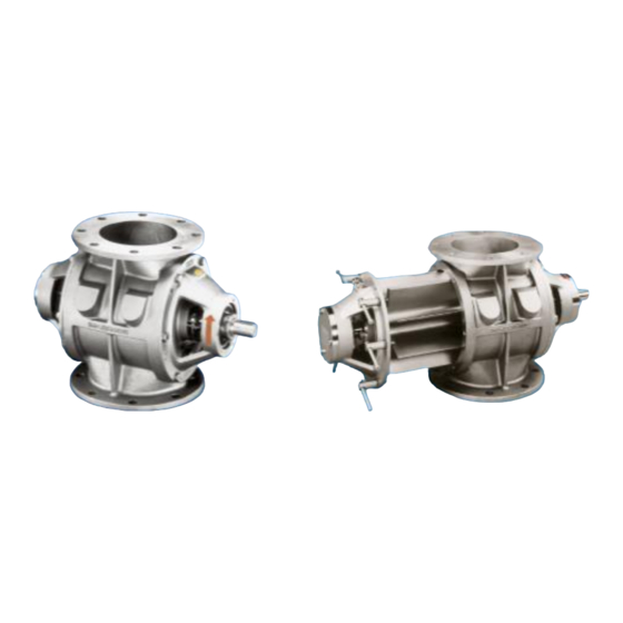
Rotary valves
Hide thumbs
Also See for AL Series:


Need help?
Do you have a question about the AL Series and is the answer not in the manual?
Questions and answers