
Related Manuals for Smeg GW Series


Summary of Contents for Smeg GW Series
- Page 1 GW1245 GW0260 - GW1260 - GW4260 GW4290 GW – LABORATORY GLASSWARE WASHERS USER MANUAL TRANSLATION OF THE ORIGINAL INSTRUCTIONS GW1245 - GW0260 - GW1260 - GW4260 - User Manual 193909119 rev.02 Page 1 – 91 GW4290...
-
Page 2: Table Of Contents
Table of Contents INITIAL INSTRUCTIONS ..........................6 INTENDED PURPOSE AND CLASSIFICATION ....................7 INTENDED PURPOSE .......................... 7 LIFE CYCLE ............................8 DEFINITION: “RESPONSIBLE BODY” IN RELATION TO THE DEVICE ............ 8 INTENDED USER AND SUPERUSER ..................... 8 PRESENTATION ............................9 CONFIGURATIONS AND OPTIONAL ACCESSORIES .................. - Page 3 PROGRAM RUNNING ........................34 8.7.1 PROGRAM RUNNING – “EASY MODE” DISPLAY ..............35 8.7.2 REPEATED CYCLES, PROGRAMMING RUNNING - OPTION RC, REPEAT CYCLE ACTIVE .... 35 PROGRAM COMPLETED ........................36 8.8.1 END OF CYCLE - AUTOMATIC DOOR OPENING (Setup - Ad Option) ........36 PROGRAM COMPLETED WITH ANOMALIES –...
- Page 4 13.4.2 FOR 24 HOURS OR MORE ......................69 13.4.3 FOR 10 DAYS OR MORE ......................69 13.5 REUSING THE DEVICE AFTER A PERIOD OUT OF USE ..............69 13.6 MAINTENANCE AND ROUTINE CHECK TIME INTERVALS ..............70 13.6.1 DAILY ............................70 13.6.2 WEEKLY ............................
- Page 5 14.9.3 CONNECTION ON REAR OF DEVICES..................87 14.9.4 45 cm DEVICE CONNECTIONS - GW1245 ................87 14.9.5 CONNECTIONS TO 60 CM DEVICE – GW0260, GW1260, GW4260 ......... 88 14.9.6 CONNECTIONS TO 90 CM DEVICE ................... 89 14.9.7 GW4290 – Position of optional LAN port ................90 AFTER-SALES SERVICE AND MANUFACTURER CONTACT DETAILS ............
-
Page 6: Initial Instructions
1 INITIAL INSTRUCTIONS READ THIS USER MANUAL WITH CARE This manual is an integral part of the device. Take good care of it and keep it to hand throughout the device’s life cycle. This manual and all the information it contains must be read carefully before using the device. Failure to read, any misunderstanding or incorrect interpretation of the instructions provided in this manual may lead to misuse of the device, put the operator at risk and impair the device’s performance. -
Page 7: Intended Purpose And Classification
2 INTENDED PURPOSE AND CLASSIFICATION 2.1 INTENDED PURPOSE PRODUCT DESCRIPTION: professional glassware washers, laboratory glassware washers (GW – glassware washer). Model Key characteristics Laboratory glassware washers, 45 cm, without drying system, washing chamber in AISI 316 GW1245 stainless steel. Laboratory glassware washers, 60 cm wide, without drying system, washing chamber in GW0260 stainless steel AISI304. -
Page 8: Life Cycle
2.2 LIFE CYCLE The “life cycle”, “lifetime” or “intended lifetime” is the period of time during which the device’s characteristics and performance do not deteriorate to an extent which impairs the efficacy of the treatment or the safety of the device. Product life cycle: 10 years or 30000 cycles, whichever is reached first. -
Page 9: Presentation
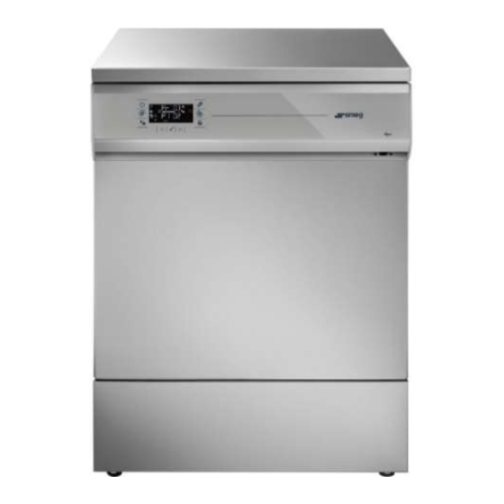
3 PRESENTATION The models referred to are small glassware washers with a single loading door. The device’s user interface consists of an LCD screen and touch buttons for user interaction. 90 cm models have a side cabinet to accommodate the detergent jerry cans, and an electrical main switch. They are also able to accommodate an optional printer to print the cycle report. -
Page 10: Table Of Accessories
4.3 Table of accessories The model may be equipped with a number of optional accessories; refer to the configuration table provided below. Key to symbols Feature present Optional feature (Some of these features can only be installed in the factory at the time of ... - Page 11 GW1245 Model Name GW0260 GW1260 GW4260 GW4290 Bottom- Bottom- Bottom- Bottom- Bottom- Type of door (bottom-hinged/sliding) hinged hinged hinged hinged hinged Number of doors (access to chamber: Single Single Single Single Single single/double) Drying system - Relative drying filter ...
-
Page 12: Ref - Configuration Identifier
4.4 REF – Configuration identifier REF: the REF of a product, which appears on its technical dataplate, is its “catalogue number”, the code which enables unique identification of its configuration. E.g. GW1260-SC-000 identifies model GW1260: 1. Equipped with peristaltic pumps P1 and P2 2. -
Page 13: Ref For Model Gw1245
4.4.1 REF for Model GW1245 Model # GW1245 is only available in the following variants: REF GW1245-S0-100 REF GW1245-SC-100 5 SAFETY AND PRECAUTIONS FOR USE 5.1 KEY TO THE SYMBOLS USED IN THE MANUAL AND ON THE DEVICE The following is the key to the symbols used on the device and in this manual, as required by IEC 61010-2- 040. - Page 14 MEANING SYMBOL Transport, storage and unpacking precautions. Biological hazard. Flammability hazard. “Crossed dustbin” symbol. This device is tagged under European Directive 2012/19/EU ON WASTE ELECTRICAL AND ELECTRONIC EQUIPMENT (WEEE) (ref. annex IX of directive). The symbol appears on the product’s technical dataplate and the pack label: at the end of its working life, the product must be consigned to a disposal plant for recovery and recycling in accordance with the relevant legislation in the country of installation.
-
Page 15: General Warnings
Communication ports may only be used as described by the manufacturer. In short: - USB port: for connecting the USB drive supplied by the manufacturer or via PC. - RS232 port: for connection to an optional external printer recommended by Smeg, ref. WD-PRINTE2. - LAN door: for network connection. - Page 16 In all cases, only equipment powered via SELV or SELV Equivalent systems may be connected to the device. Check the device’s power supply. Maintenance: change drying filter (if installed) The device provides an alert when the filter needs changing. Keeping the filter in operation after the end of its useful life will lead to poor drying results.
-
Page 17: Warnings For Handling The Device
Network access to the PC on which the application is installed must be restricted to personnel authorised by the facility and the IT system must have suitable security protection. A secure internal network should always be provided for communication between authorised PCs and Smeg devices. GW1245 - GW0260 - GW1260 - GW4260 - User Manual 193909119 rev.02... -
Page 18: Accessing And Reusing The Device After An Incomplete Cycle And Accessing The Device At End-Of-Life
5.5 ACCESSING AND REUSING THE DEVICE AFTER AN INCOMPLETE CYCLE AND ACCESSING THE DEVICE AT END-OF-LIFE The instructions relating to the device’s safety in the event of an incomplete operating cycle are provided in IEC 61010-2-040. WARNING – Applies if the device is used for processing biologically contaminated material. The load and the internal parts of the device might be biologically contaminated/infected. -
Page 19: Opening And Closing Of The Door
6 OPENING AND CLOSING OF THE DOOR We consider the door opening procedure here to enable access to the bag containing the accessories, which is placed inside the washing chamber for shipment. If installed, turn the electrical main switch on. Then proceed as follows: 1. -
Page 20: Manual Door Unlocking / Opening Procedure
6.1 MANUAL DOOR UNLOCKING / OPENING PROCEDURE Warning: before opening the device manually, disconnect it from the electricity supply. If necessary, due to a malfunction or power blackout, the appliance can be opened manually by releasing the lock using a screwdriver with stem Ø 4 mm; be gentle, taking care not to damage the device. 1. -
Page 21: Opening The Hatch Of The Side Cabinet - Gw4290 Only
6.2 OPENING THE HATCH OF THE SIDE CABINET – GW4290 ONLY The GW4290 model has a side cabinet. Opening its hatch gives access to: Main switch (circuit-breaker) Panel printer (if installed) Jerry cans for detergents Fig. 4– Opening the GW4290 side cabinet hatch. Once the side cabinet hatch is open, the user has access to the device’s main switch (and the printer, if installed). -
Page 22: Commissioning
7 COMMISSIONING Once the device has been installed correctly, it must be prepared for use. The following operations must be carried out: 1. Set the current date and time. 2. Fill up with regenerating salt. 3. Set the language required. 4. -
Page 23: Adjusting The Spray Arm Washing Pressure
7.2 ADJUSTING THE SPRAY ARM WASHING PRESSURE The adjuster device provided underneath the chamber’s lower spray arm can be used to adjust the washing water pressure in the upper and lower spray arms. Setting 1: maximum flow-rate in upper level. ... -
Page 24: Liquid Detergent Suction System - Replacing An Empty Jerry Can
7.3.1 LIQUID DETERGENT SUCTION SYSTEM – REPLACING AN EMPTY JERRY CAN Each peristaltic pump is complete with a detergent intake system. The suction system comprises: 1. Intake nozzle, consisting of stiff plastic part tapered rubber support to fit firmly onto the jerry can outlet. - Page 25 Detergent jerry cans must be securely positioned: - inside the side cabinet, on 90 cm models: GW4290. - near the device, on a specific, stable surface, for 45 cm and 60 cm models: GW1245, GW0260, GW1260 and GW4260. Example of placing of jerry cans near the device for devices without side cabinet. GW1245 - GW0260 - GW1260 - GW4260 - User Manual 193909119 rev.02...
-
Page 26: Basic Operation
8 BASIC OPERATION 8.1 CONTROL AREA The device’s controls and indicator icons are on its front panel. The central area comprises an LCD display with information about the cycle parameters and setup parameters, and indicator icons. The touch buttons for interaction with the device are beside and underneath the display. Different functions can be obtained by pressing a button briefly or holding it down (2 seconds). -
Page 27: Buttons
8.2 BUTTONS Icon Main function Secondary function On/Off (hold down for action). [The button is not a main switch; the device is still powered up even in OFF condition.] Drying decrease (4260, 4290) Decreases the value of the selected parameter. Decreases the value of the selected parameter (1245, 0260, 1260). -
Page 28: Display And Icons
8.3 DISPLAY AND ICONS The central display consists of two main lines, which show program and machine parameter information, and a series of icons used for information about the cycle in progress and the status of the device. All the icons appear for a few seconds when the device is switched on, to enable an immediate check that the display is working correctly. - Page 29 ICON MEANING – With cycle selected MEANING – With cycle running Start/Stop icon: indicates that the cycle On (not flashing): identifies that can be started. the button can be pressed to stop the cycle. Padlock icon. On (not flashing): door is On (not flashing): door is locked.
-
Page 30: With Cycle Preselected - Information About Program Parameters
8.4 With cycle preselected – information about program parameters After switch-on, the device goes to the latest program run. The display shows some essential data for the program. Facsimile of central display Description of information Pr 02: the second program in the list. Td: the program includes thermal disinfection. -
Page 31: Adjustments To Current Program
5. IDprog – unique program Id number. 6. Use of demineralised water - DW ON (DW stands for “Demi water”). The operator can temporarily disable the use of demineralised water, in which case “DW OF” displays. 7. Time set for delayed cycle start - DS 00 (DS stands for “Delayed Start”). - Page 32 Second reduction, total time about 11 minutes. Steps 1, 2 and 4 are retained as above; step 3 is not performed. Third reduction, total time about 3 minutes. Only Step 4 described above is performed, to facilitate venting of the steam and to cool the load. Fourth reduction, drying phase completely eliminated.
-
Page 33: Selecting A Program
From the selected program: scroll the cycle parameters on the second line to function DS, associated to the delayed start. Initially, the display shows “DS 00”. The numerical value indicates the number of hours of delay. E.g.: “00” means the cycle will start with no delay, when the start button is pressed. -
Page 34: Starting The Program
8.6 STARTING THE PROGRAM After selecting the program required, lock the door and press Start to start it. 8.7 PROGRAM RUNNING When a cycle is running the following appear on the display in rotation: 1. The number of the program now running is on the top line. 2. -
Page 35: Program Running - "Easy Mode" Display
8.7.1 PROGRAM RUNNING – “EASY MODE” DISPLAY Simplified “Easy Mode” display of the cycle in progress can be selected (see “Setup” menu for setting procedure). In this case the information shown remains permanently on the display and is not rolling. The second line of the display shows the current temperature in the chamber and the other parameters of the phase in progress can only be scrolled using the Gears (Functions) button. -
Page 36: Program Completed
8.8 PROGRAM COMPLETED Program completed successfully: the word END appears on the second line of the display. Unlock the door with the “padlock” button to open the door, extract the trolley and collect the load. Only if the cycle was completed successfully (indicated by the word END), the word “OPEN” appears on the display when the door is then opened. -
Page 37: Program Completed With Anomalies - Warnings
8.9 PROGRAM COMPLETED WITH ANOMALIES – WARNINGS If the program has been completed but events to which the user must be alerted have occurred, the code of the anomaly appears on the second line with the prefix “W” for “Warning”. The user must refer to the Warning table to assess the alert. -
Page 38: Setup And Parameter Setting Procedures
9 SETUP AND PARAMETER SETTING PROCEDURES The device has setup procedures for modifying some operating parameters. The setup menu comprises all the functions required for setting the machine parameters and for maintaining and inspecting the device. These menus are password-protected to restrict access to them: the device’s parameter setting menus can only be accessed with the password supplied to authorised engineers. - Page 39 Menu SubMenu Meaning Range User Superuser Engineer IT, EN, FR, Printer language R + W R + W DE, ES, PT, PL Printer type 00, 01, 02, R + W R + W Demi water ON, OF R + W Electrical 7.0, 3.0 R + W...
-
Page 40: Accessing The Menus
Menu SubMenu Meaning Range User Superuser Engineer PARAM Reprint parameters Saving of log on USB R + W R + W ERASE Cycles log deletion Displays FW About versions. Input and output IOTEC R + W status 9.1 Accessing the menus Description Illustration Hold down button P1 Functions and the display... - Page 41 SETUP menu items Typical screens (guideline illustrations) P1 – dosage [field only displayed if P1 is installed] Dosage in ml/litre associated to peristaltic pump [With a decimal point for values from 0.5 to 10 ml/litre. From 10 ml/litre: the character on the right indicates the units and the decimal point disappears].
- Page 42 SETUP menu items Typical screens (guideline illustrations) PR – Printer (optional) language [PR stands for “Printer”] Default is “EN” printout in English. P2 and P8 scroll through the other languages available: IT, EN, FR, DE, ES, PT, PL. Prt – Printer type [Prt stands for “printer type”] PRt00 ->...
- Page 43 SETUP menu items Typical screens (guideline illustrations) NT – LAN connection NT stands for Network. This parameter refers to the presence or absence of the component which allows connection of the device to a network. NT-OF (default): LAN connection absent. NT-ON: LAN connection present.
-
Page 44: Setting The Time - Clock Menu
SETUP menu items Typical screens (guideline illustrations) DC – Drain cooling Cooling of the drain If the value is “00”: only the engineer can modify the value. If the value is different from “00”: the superuser can access the edit function and change the value from “65” up to “80”. - Page 45 Description Illustration Press P5 to enter Clock edit mode: the word Clock will now be underlined. The digits flash while they are being edited: increase and decrease using buttons P2 and Use buttons P4 or P6 to switch from setting to minutes to hours.
-
Page 46: Setting The Date - Date Menu
9.4 SETTING THE DATE – Date menu Description Illustration Hold down button P1 Functions and the display will await the credentials which establish the level of access for the setup menus: enter the level and password. To enter the specific menu: from the Setup menu, press the right button P4 to scroll to the Date function. -
Page 47: Cycle Counter - Count
9.6 CYCLE COUNTER – Count Description Illustration Count: device cycle counter, absolute and incremental. Cannot be modified. [Can only initialised by authorised engineers using an external application when the motherboard is replaced.] 9.7 PROGRAM ENABLING – PR EN PR EN (Program enabling) Setting which allows display and selection only of the washing programs actually of interest. -
Page 48: Reset Me - Machine Equipment
9.8.2 RESET ME – Machine Equipment Machine Equipment Parameter which the engineer can force restoration of the equipment values to the factory values. This resets all the values relating to the equipment, meaning the components actually present and installed on the device. The default setting of the parameter is “UV”... -
Page 49: Reset Rm - Number Of Cycles Remaining Before Maintenance
9.8.4 Reset RM – Number of cycles remaining before maintenance RM – Residual Maintenance Cycles Cycles remaining before maintenance. The parameter indicates, to the nearest ten, the number of cycles remaining before routine maintenance (“RM-90” on the display indicates that there are 900 cycles left before the maintenance warning). -
Page 50: Log - Management Of Internal Log, Downloading Of Log File To Usb Drive
9.10 LOG – Management of internal log, downloading of log file to USB drive LOG: menu for managing the internal memory log. The second line of the display contains two items: USB: for saving the log on USB drive. ERASE: for clearing the internal memory log. -
Page 51: Memory And Printout
9.12 MEMORY AND PRINTOUT Terms and abbreviations used and their meanings Cold water. Example: “Load CW / 9L” means: load cold water, 9 litres. Hot water Demineralised water (demi water) CW+HW Cold water and hot water Litres – The amount of water loaded during a phase. PREWASH, WASH, THERMAL... - Page 52 Example cycle archive Description of items 2017/05/29 12:48:41 Cycle started Cycle started – date and time of cycle start. ID 12 ID.12 – the ID number of the program (“ID_prog” in the User 255 Programs Table). Cycle N. 59 Cycle N. 59 –...
-
Page 53: Editing Custom Programs
9.13 EDITING CUSTOM PROGRAMS Warning: construction of a custom washing program requires specific knowledge both of the load treatment process and of the parameters of the device being used. A program can only be edited using the external app supplied by the Manufacturer and only by the person responsible for the device within the facility (the “Superuser”). - Page 54 N.B.: pumps P3 and P4 are always optional. Recommended detergents for GW products – Laboratory sector P1 – Alkaline detergents Smeg Strong universal alkaline liquid detergent. Recommended for various kinds of soil, DETERLIQUID C2 especially organic chemical, pharmaceutical and general Smeg Alkaline liquid detergent containing potassium hydroxide.
- Page 55 GENERAL PRECAUTIONS FOR MANAGING DETERGENTS AND REPLACING JERRY CANS HANDLE DETERGENT JERRY CANS WITH CARE Warning: detergents may be TOXIC. Refer to the product safety data sheets. If the product left in the old can is poured into the new one, take care not to overfill the new cans to ensure that they will not overflow when the suction nozzles are inserted.
-
Page 56: Preparing The Load For The Washing And Disinfection Cycle
11 PREPARING THE LOAD FOR THE WASHING AND DISINFECTION CYCLE Loading instructions are provided in compliance with 5.4.4. k of IEC 61010-2-040. Effective washing starts with preparation of the load: the load must be appropriately arranged on the most suitable supports. Before placing the items which make up the load in the baskets provided, remove any large residues deriving from previous use, by soaking, treatment or rinsing as appropriate. -
Page 57: Alarms, Warning And Device Response To Blackouts
12 ALARMS, WARNING AND DEVICE RESPONSE TO BLACKOUTS This section provides instructions for interpreting alarm messages and taking any appropriate measures. Information supplied in compliance with point 5.4.4. j of IEC 61010-2-040. The messages relating to operating anomalies are divided into two groups on the basis of their severity: 1. -
Page 58: Warnings
12.1 WARNINGS With these alerts active, the user can complete the washing cycle after acknowledging the warning by pressing the Confirm button in the centre. If two or more warnings are present the Confirm button will have to be pressed twice or more before the cycle can be started. -
Page 59: Warning Table
12.1.1 WARNING TABLE All the codes below refer to warnings; they are not alarms which stop the cycle. Use of the device can be continued, but repeated or significant warnings should be reported to the after-sales service. DESCRIPTION USER ACTION The use of a mixture of water is an option adopted in special cases to cool the water discharged into the drain. -
Page 60: Alarms
12.2 ALARMS The device signals an alarm event with the specific icon and the code of the alarm on the second line of the display. The user must press the Confirm button to acknowledge the alarm. Example of display of alarm code and Alarm Icon. Alarm acknowledgement –... -
Page 61: Alarm Table
12.2.1 ALARM TABLE ALARM ID DESCRIPTION USER ACTION Water not heated within time AF:01 allowed. The temperature difference between the two probes, “TL1” AF:02 and “TC”, is more than 2 °C (only active on WD). Probe “TL1” (tank temperature) User: follow the DEFAULT PROCEDURE described above. If the AF:04 shows a reading higher than the alarm does not disappear, follow the RESET PROCEDURE. - Page 62 ALARM ID DESCRIPTION USER ACTION There may be foam in the tank. The lack of pressure may be due to the use of special trolleys which require more than the usual amount of water to keep their water circuits operating correctly. Water circuit malfunction.
- Page 63 ALARM ID DESCRIPTION USER ACTION 2. Check for detergent leaks (pools of detergent around the W / AF:43 P3 detergent intake anomaly device). W / AF:44 P4 detergent intake anomaly The code is an alarm if it is preceded by AF. P1 pump active when not Check that the detergents are not crystallised and are being W / AF:46...
- Page 64 ALARM ID DESCRIPTION USER ACTION This alarm is only tripped if the device parameter that prevents overwriting in the memory is enabled. Memory space must be freed to allow use of the device to AF:91 Internal memory full. continue: this can be done by connecting to the device by means of the external app or using the procedures described in the manual for management of the log and the USB drive.
-
Page 65: Cleaning And Maintenance
13 CLEANING AND MAINTENANCE 13.1 PRELIMINARY PRECAUTIONS .Before any cleaning or maintenance procedure: it is advisable to perform a high temperature cycle with the device empty (with no load in the chamber). .Then disconnect the power supply using the main switch and turn off the water intake taps. .Always use personal protection equipment. - Page 66 CLEANING THE DETERGENT COMPARTMENT [when provided] The detergent jerry can compartment must be inspected daily: check for any leaks or spills of chemicals; remove any standing liquids; when cleaning, it is essential to use the appropriate personal protection equipment, as recommended in the technical and safety data sheets of the chemicals used;...
- Page 67 Cleaning the water intake filter Water intake filter “A” on the tap must be cleaned from time to time; this should be done 1 every 2 – 6 months, depending on the quantity of water used. Turn off the water supply tap, unscrew the end of the water intake hose, remove filter “A”...
-
Page 68: Cleaning The Filtering Unit
13.3 Cleaning the FILTERING UNIT The filtering unit consists of several different parts. To ensure that the device operates effectively, it is important to keep the filters clean. They should be inspected frequently. If 2 – 3 cycles are performed per day, the filters should be cleaned once a week to remove deposits which may adversely affect operation. -
Page 69: If The Device Is To Be Out Of Use
13.4 IF THE DEVICE IS TO BE OUT OF USE If you intend to leave the device out of use, proceed as follows. 13.4.1 FOR A FEW HOURS If the device is to be unused and unattended for a few hours (e.g. overnight), proceed as follows: 1. -
Page 70: Maintenance And Routine Check Time Intervals
13.6 MAINTENANCE AND ROUTINE CHECK TIME INTERVALS 13.6.1 DAILY 1. Check the detergent and neutralising agent levels in the jerry cans and fill up if necessary. 2. Check movement of the spray arms and visually inspect the water outlet holes to ensure that they are clean. -
Page 71: Troubleshooting
13.7 TROUBLESHOOTING In some cases it is possible to remedy minor problems with the aid of the following instructions. 1. If the program does not start, check that: The device is connected to the electrical mains. There is no power outage. ... -
Page 72: Installation
14 INSTALLATION The preparatory operations for commissioning of the device are the responsibility of the Customer: Preparation of the premises and correctly functioning systems, in accordance with the relevant requirements and regulations; Positioning of the device in the installation area. The device's characteristics and positioning and installation instructions are provided below. -
Page 73: Installation On Stand
Accurate levelling is important to enable the device to function correctly. WARNING Any adjustments and maintenance must be done with the device disconnected from its power supply. 14.3 INSTALLATION ON STAND The device can be installed on a stand with height X = 400 mm. Note: The raising base is not provided for the 45cm models, GW1245. -
Page 74: Electrical Connection Requirements
14.4 ELECTRICAL CONNECTION REQUIREMENTS WARNING The electrical system to which the device is connected must comply with the regulations in force. All electrical checks and system installation must be carried out to the proper standard by skilled staff qualified to work on electrical systems. The skilled staff are responsible for ensuring that the ground connection is in good working order. -
Page 75: Power Supply Cable - Gw1245
14.4.2 Power supply cable - GW1245 Characteristics of the power supply cable supplied with the device. H07RN-F 3 x 1.5 mm (3G1.5), 450/750 V, (single-phase version). 14.5 WATER CONNECTION REQUIREMENTS Legend of abbreviations used for the water intake connections. CODE INTAKE/DRAIN WATER TYPE INTAKE... -
Page 76: Demineralised Water Requirements
Notes: If the hose is new or has been unused for a long time, before connecting it make sure that the water is clear and free of impurities. If the supply system does not provide both hot and cold water connections, the two hoses must be connected together by means of the “Y”... -
Page 77: Unpressurised Demineralised Water - Optional Accessory "Pad
14.5.3 UNPRESSURISED DEMINERALISED WATER – OPTIONAL ACCESSORY “PAD” If the demineralised water connection is not pressurised, a special booster pump “PAD”, available in due versions “PAD1” and “PAD2X”, can be installed. Pump “PAD1” is installed on the outside of the rear of the device. ... -
Page 78: Water Drain Requirements
14.6 WATER DRAIN REQUIREMENTS WARNING The drain must comply with international regulations: the manufacturer accepts no liability for pollution caused by misuse of the device. The water drain may contain biological contaminated materials. It must be managed and treated in accordance with the regulations in force in the country of installation. -
Page 79: Technical Characteristics
14.7 TECHNICAL CHARACTERISTICS 14.7.1 WATER CONNECTIONS “CW” COLD WATER Connection required: 3/4" – DN20 Flow-rate required [min – max]: 4 – 12 lt/min Pressure [min – max]: 100 – 600 kPa (1 – 6 bar) Temperature [min – max]: 8 – 35 °C (46 °F – 77 °F) 42 °f Max hardness: [To reduce wear of the steam condenser, if installed, hardness... -
Page 80: Electrical Connections - 45 Cm Devices [Gw1245]
14.7.2 ELECTRICAL CONNECTIONS – 45 CM DEVICES [GW1245] Connection to 230 V single-phase Power supply: 230 V ~ / 50 Hz / 13 A /2950 W Characteristics of main switch and electrical protection device required 1P+N, 16 A within system: 14.7.3 ELECTRICAL CONNECTIONS–... -
Page 81: Ambient Conditions
14.7.4 AMBIENT CONDITIONS Indoor Max altitude Up to 1,000 m above sea level Temperature [min – max] From 5 °C to 40 °C Minimum lighting level required 300 lx Max humidity 80% for temperatures up to 31 °C with linear decrease to 50% at the temperature of 40 °C. -
Page 82: Dimensions Of Product And Connections
14.8 DIMENSIONS OF PRODUCT AND CONNECTIONS 14.8.1 GW1245 N.B.: all dimensions are in mm. Standard product dimensions Simplified diagram, overall dimensions of standard product. The space considered for the jerry cans at the side is guideline. Product dimensions if optional components are installed * The greater depth of 770 mm refers to the product when optional accessory PAD1 is installed. -
Page 83: Gw0260 - Gw1260 - Gw4260
14.8.2 GW0260 - GW1260 - GW4260 N.B.: all dimensions are in mm. Standard product dimensions Simplified diagram, overall dimensions of standard product. The space considered for the jerry cans at the side is guideline. Product dimensions if optional components are installed * The greater depth of 750mm refers to the product when optional PAD1 or the optionals associated to peristaltic pumps P3 or P4 are installed. -
Page 84: Gw4290
14.8.3 GW4290 All dimensions are in mm. Standard product dimensions Simplified diagram, overall dimensions of standard product. The side cabinet, on the right, contains the detergent jerry cans. Product dimensions if optional components are installed * The greater depth of 750 mm refers to the product when optional PAD1 is installed; on these 90 cm models installation of the optional peristaltic pumps P3 or P4 does not imply an increase in depth, as they are mounted in the side cabinet. -
Page 85: Connections Area - Electricity And Water
14.9 CONNECTIONS AREA – ELECTRICITY AND WATER The diagram provides guidance on the permitted areas for: 1. Electrical connection. 2. Water intake connection – cold, hot and demineralised water CW, HW and DW taps. 3. Drain connection – D (Drain). Electrical Connection Area: recommended area for the device’s electrical connection, depends on the accessibility of the connection and the length of the power supply cable provided. -
Page 86: Cm Devices [Gw1245]
14.9.1 45 cm DEVICES [GW1245] Simplified diagram: the water intake and drain connections can be provided on the left or right of the device, depending on requirements. *N.B.: the condenser drain (CD) connection is only present on configurations equipped with steam condenser, e.g. -
Page 87: Connection On Rear Of Devices
14.9.3 CONNECTION ON REAR OF DEVICES Legend DESCRIPTION Demi water intake hose Cold mains water intake hose Hot mains water intake hose Power supply cable Water drain hose steam condenser drain hose - CD (condenser drain). [Only the 45 cm model, GW1245, in version equipped with condenser, e.g. REF. GW1245-SC-100, is fitted with an additional drain pipe for the steam condenser]. -
Page 88: Connections To 60 Cm Device - Gw0260, Gw1260, Gw4260
14.9.5 CONNECTIONS TO 60 CM DEVICE – GW0260, GW1260, GW4260 Rear view Front view The position of the USB port is marked GW1245 - GW0260 - GW1260 - GW4260 - User Manual 193909119 rev.02 Page 88 – 91 GW4290... -
Page 89: Connections To 90 Cm Device
14.9.6 CONNECTIONS TO 90 CM DEVICE GW4290 rear view GW4290 front view The USB port is marked. The side hatch of the cabinet is not shown. On GW4290, detergent intake connections “P1” and “P2” are inside the right-hand side cabinet. The connections are marked for identification with P1 (detergent) and P2 (neutraliser). -
Page 90: Gw4290 - Position Of Optional Lan Port
14.9.7 GW4290 – Position of optional LAN port Fig. 20 – Position of the optional LAN port on the rear of the device. [GW4290 does not have an RS232 port as it is designed for installation of a built-in panel printer.] GW1245 - GW0260 - GW1260 - GW4260 - User Manual 193909119 rev.02... -
Page 91: After-Sales Service And Manufacturer Contact Details
Single contact number for Italy +39 0522.160.60.50 Email: assistenza.instruments@smeg.it For sales information: Email: instruments@smeg.it International Customers Please contact your Local Smeg Distributor or write an email to service.instruments@smeg.it GW1245 - GW0260 - GW1260 - GW4260 - User Manual 193909119 rev.02 Page 91 – 91 GW4290...
Need help?
Do you have a question about the GW Series and is the answer not in the manual?
Questions and answers
how do i become a superuser