
Related Manuals for Smeg WD6010


Summary of Contents for Smeg WD6010
- Page 1 WD6010 WD7010 WD7015 WD6010 – WD7010 – WD7015 WD – WASHER DISINFECTOR – Hospital sector - USER MANUAL - Translation of the original instructions issued in Italian...
-
Page 2: Table Of Contents
DEFINITION: “RESPONSIBLE BODY” OF THE DEVICE ................ 11 TYPE OPERATOR AND “SUPERUSER” ....................11 PRESENTATION ............................12 WD6010 and GW6010 - MACHINE WITH SWINGING DOOR ............13 WD7010 - GW7010, WD7015 – GW7015 – MACHINE WITH SLIDING DOORS ........ 16 4.2.1 OPTIONAL BARCODE SCANNER –... - Page 3 7.1.1 WD6010 - GW6010 ........................44 7.1.2 WD7010 - GW7010 – WD7015 – GW7015 ................45 USE OF DETERGENTS ........................45 7.2.1 LIQUID DETERGENT SUCTION SYSTEM ..................46 DETERGENTS ............................47 LOAD PREPARATION FOR WASH CYCLE AND DISINFECTION..............49 BASIC OPERATIONS ..........................52 10.1...
- Page 4 DEVICE RE-USE AFTER A PERIOD OF IDLENESS ................141 13.6 TIME SCHEDULE FOR ROUTINE MAINTENANCE AND CHECKS ............142 13.6.1 DAILY ............................142 13.6.2 WEEKLY ..........................142 13.6.3 EVERY SIX MONTHS ....................... 142 USER MANUAL WD6010 – WD7010 – WD7015 Page 4 - 168...
- Page 5 WATER DRAIN ..........................159 14.7 STEAM SYSTEM CONNECTION (OPTIONAL) ................... 162 14.8 CHAMBER VENT CONNECTION (AIR AND STEAM) ................ 163 TECHNICAL CHARACTERISTICS ......................164 MANUFACTURER REFERENCES AND AFTER-SALES SERVICE ............. 168 USER MANUAL WD6010 – WD7010 – WD7015 Page 5 - 168...
- Page 6 1. Management of new optional Barcode Scanner (ref. “WD-CODESCAN”). 2. Management of “Signal Box”, optional accessory for interfacing device status signals for external communications (ref. “WD-SIGNBOX15”). 3. Management of interfacing between device and Smeg Energy Management app (ref. “WD- 193906237 – IT 11/03/2022 EMS”).
-
Page 7: Initial Reccomendations
The content of this manual is for information purposes only. The content and the equipment described here may be subject to change without notification. The colours used in photographs of the product (finishing panels), in diagrams and in screenshots are all purely guideline. USER MANUAL WD6010 – WD7010 – WD7015 Page 7 - 168... -
Page 8: Service Life
The washing cart functions in support of the load and determines the typology of instruments that can be processed in a cycle. (The base device is supplied without washing USER MANUAL WD6010 – WD7010 – WD7015 Page 8 - 168... -
Page 9: Wd Classification
Instrument washers for hospital use, medical devices in class IIb (in compliance with the classification criteria stated by the Directive 93/42 and later changes and additions, reviewed and amended by directive 2007/47/EC - attachment IX, rule 15). USER MANUAL WD6010 – WD7010 – WD7015 Page 9 - 168... -
Page 10: Standard 15883
WARNING – USE OF PROBES FOR VALIDATION The base machine is not equipped with a physical door to insert probes with cables: we recommend the use of wireless probes (datalogger or similar). USER MANUAL WD6010 – WD7010 – WD7015 Page 10 - 168... -
Page 11: Definition: "Responsible Body" Of The Device
Staff training should be checked regularly. The installer technician is responsible for the correct functioning of the appliance after the installation. Safety information provided in compliance with 5.4.101.1 IEC61010-2-040:2015. USER MANUAL WD6010 – WD7010 – WD7015 Page 11 - 168... -
Page 12: Presentation
“Clean side”: the operator can only unlock the door to unload items once the cycle has been completed successfully. From the clean side it is also possible to interrupt a cycle in progress. A cycle can be started only if the doors are closed. USER MANUAL WD6010 – WD7010 – WD7015 Page 12 - 168... -
Page 13: Wd6010 And Gw6010 - Machine With Swinging Door
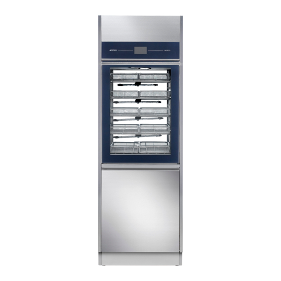
4.1 WD6010 and GW6010 - MACHINE WITH SWINGING DOOR DEVICE VERSION IMAGE SINGLE DOOR MACHINE There is a small lower door to access the detergent compartment and the electricity supply disconnector. DOUBLE DOOR MACHINE IMPORTANT: in the double door version, on the load side only, there is a lower door to access the detergent compartment and the electricity supply disconnector. - Page 14 The detergent jerrycans are not visible, but the following can be seen: - detergent suction lances with level sensor - air filters for drying system (dryer) - peristaltic pumps (pumps for liquid detergent dosage) USER MANUAL WD6010 – WD7010 – WD7015 Page 14 - 168...
- Page 15 BE ON THE RIGHT SIDE CART EXTRACTOR HOLDER MOUNTED ON THE DOOR “UNCLEAN” SIDE (“LOADING” SIDE) VIEW of the device: the extracted cart is positioned on the door with stops to limit movement. USER MANUAL WD6010 – WD7010 – WD7015 Page 15 - 168...
-
Page 16: Wd7010 - Gw7010, Wd7015 - Gw7015 - Machine With Sliding Doors
TOUCH SCREEN INTERFACE MAIN SWITCH ON-OFF SWITCH SAFETY KEY FOR SOLE USE OF AUTHORISED TECHNICAL STAFF OPTIONAL PRINTER USB PORT VIEW OF "UNCLEAN" SIDE (LOADING SIDE) of the device. USER MANUAL WD6010 – WD7010 – WD7015 Page 16 - 168... - Page 17 TECHNICAL STAFF OPTIONAL PRINTER USB PORT VIEW OF "UNCLEAN" SIDE (LOADING SIDE) of the device. On the WD7015, GW7015 models the touch screen interface is on the side control panel. USER MANUAL WD6010 – WD7010 – WD7015 Page 17 - 168...
- Page 18 - detergent jerrycan compartment (detergent jerrycans and intake nozzle) - dryer air filters - peristaltic pumps (liquid detergent dispensing pumps). WARNING: If the detergent compartment is open, the loading side door cannot be operated. USER MANUAL WD6010 – WD7010 – WD7015 Page 18 - 168...
- Page 19 WARNING: once the “emergency button” has been pressed, it must be rearmed (by turning it) in order to restart the device. The device should also be switched off and back on with the main switch before restarting normal use. USER MANUAL WD6010 – WD7010 – WD7015 Page 19 - 168...
-
Page 20: Optional Barcode Scanner - Wd-Codescan
N.B.: When acquired, the rack code is not automatically paired with the program to be executed. For this to take place, the device and racks must be equipped with additional optionals (e.g. MAGBAR” and “RACKREC” (Rack Recognition) - contact authorised Smeg personnel for further information). - Page 21 [Guideline barcode dimensions: 70x18mm]. Contact authorised after-sales personnel for further information. WD7015 equipped with barcode scanner Detail of scanner (guideline illustration) USER MANUAL WD6010 – WD7010 – WD7015 Page 21 - 168...
-
Page 22: Configurations And Optionals
Unless otherwise specified, the device is set for a power supply of three-phase plus neutral with 400V between phases (400V 3N~). This configuration is also referred to as "standard" (“std”). USER MANUAL WD6010 – WD7010 – WD7015 Page 22 - 168... -
Page 23: Models Without Steam Heating
50 Hz 60 Hz 50 Hz 60 Hz 60 Hz 50 Hz 60 Hz 60 Hz 380-400V 380-400V 220-230V 380-400V 380-400V Notes for electrical connection 230V 3~ Steam heating system USER MANUAL WD6010 – WD7010 – WD7015 Page 23 - 168... -
Page 24: Models Equipped With Steam Heating System
Warm water boiler Demineralized water boiler Mains frequency 50 Hz 50 Hz 50 Hz 50 Hz Notes for electrical connection Steam heating system USER MANUAL WD6010 – WD7010 – WD7015 Page 24 - 168... -
Page 25: 50Hz Models
50 Hz 50 Hz 50 Hz 50 Hz Notes for electrical connection 230V 3~ 230V 3~ 230V 3~ 230V 3~ Steam heating USER MANUAL WD6010 – WD7010 – WD7015 Page 25 - 168... -
Page 26: 60Hz Models
Mains frequency 60 Hz 60 Hz 60 Hz 60 Hz 60 Hz 60 Hz 60 Hz 60 Hz Notes for electrical 220-230V 3~ 220-230V 3~ 220-230V 3~ 220-230V 3~ connection USER MANUAL WD6010 – WD7010 – WD7015 Page 26 - 168... -
Page 27: Wd7015 Models 50Hz, 400V 3N
Steam heating – boilers Barcode Scanner WD-CODESCAN Signals box WD-SIGNBOX15 Mains frequency 50 Hz 50 Hz 50 Hz 50 Hz Notes for electrical connection USER MANUAL WD6010 – WD7010 – WD7015 Page 27 - 168... -
Page 28: Wd7015 Models 50Hz, 230V 3
Signals box WD-SIGNBOX15 Mains frequency 50 Hz 50 Hz 50 Hz 50 Hz Notes for electrical connection 230V 3~ 230V 3~ 230V 3~ 230V 3~ USER MANUAL WD6010 – WD7010 – WD7015 Page 28 - 168... -
Page 29: Wd7015 Models 60Hz
Steam heating – chamber Steam heating – boilers Barcode Scanner WD-CODESCAN Signals box WD-SIGNBOX15 Mains frequency 60 Hz 60 Hz 380-400V 380-400V Notes for electrical connection USER MANUAL WD6010 – WD7010 – WD7015 Page 29 - 168... -
Page 30: Safety And Handling Precautions
Avoid any contact with live parts if electricity is on. Specific notes and regulations for Hospital sector. USB port – data communication and device setup Transport, storing and unpacking regulations. Biohazard. Fire danger. USER MANUAL WD6010 – WD7010 – WD7015 Page 30 - 168... - Page 31 The symbol is on the specific label of the machine and in this manual to identify a medical device with CE certification released by IMQ (“0051” is the identification number of the notified body IMQ). USER MANUAL WD6010 – WD7010 – WD7015 Page 31 - 168...
-
Page 32: General Recommendations
Never attempt to open the door with a program running. The appliance's control system prevents this for safety reasons. Never attempt to force the door open by hand. USER MANUAL WD6010 – WD7010 – WD7015 Page 32 - 168... - Page 33 Do not introduce flammable substances to the device. Do not use flammable detergents. Do not introduce alcohol or solvents such as turpentine, which might cause an explosion. Do not introduce materials dirty with ash, wax or paint. USER MANUAL WD6010 – WD7010 – WD7015 Page 33 - 168...
-
Page 34: Automatic Loading And Unloading Systems Cb7015 System Safety Precautions
CB7015. In this case, the device is unusable. DISCONNECTING CB7015 FROM THE DEVICE The special “CB SAFETY PIN” (shown here) must always be used when disconnecting the system from the device. USER MANUAL WD6010 – WD7010 – WD7015 Page 34 - 168... -
Page 35: Recommendations For Transport
(maximum angular tolerance permitted: 0.5°, corresponding to a maximum gap permitted on the extreme points of the machine of about 5mm). Levelling the device properly helps its correct operation. USER MANUAL WD6010 – WD7010 – WD7015 Page 35 - 168... - Page 36 The structure of the machine is fastened to the pallet: it must be unfastened to move the machine. The use of a tail lift is recommended. USER MANUAL WD6010 – WD7010 – WD7015 Page 36 - 168...
-
Page 37: Accessing And Reusing The Device After An Incomplete Cycle
Contact the authorized dealer for information about the most suitable multi-purpose trolley. Sample image of the for washing cart transport and device tending. release trolley USER MANUAL WD6010 – WD7010 – WD7015 Page 37 - 168... -
Page 38: Door Opening, Door Closing
If the machine door is closed, it can be locked or If the machine door is open, it is not possible to unlocked with the touch screen. activate / deactivate the safety door-locking mechanism. USER MANUAL WD6010 – WD7010 – WD7015 Page 38 - 168... - Page 39 Let the cart slide completely inside the washing tank Close the door of the device using the handle When the door is closed, it is possible to lock the door using the touch interface “lock” symbol. USER MANUAL WD6010 – WD7010 – WD7015 Page 39 - 168...
-
Page 40: Wd7010 - Wd7015
Machine with "double door": A door can only be opened if the door on the other side is locked. DOOR OPEN ICON - The open padlock means "door open”. USER MANUAL WD6010 – WD7010 – WD7015 Page 40 - 168... - Page 41 CLOSE: Button for closing the sliding door (UPWARD travel). Icon – door 1 current status, unclean side The blue bar indicates the active side for the user. Icon – door 2 current status, clean side USER MANUAL WD6010 – WD7010 – WD7015 Page 41 - 168...
-
Page 42: Manual Door Unlock
At any rate, all precautions must be observed. To learn more about the precautions in detail, refer to the paragraph called ACCESSING AND REUSING THE DEVICE AFTER AN INCOMPLETE CYCLE. Contact the authorized technicians for detailed information on how to unlock doors manually. USER MANUAL WD6010 – WD7010 – WD7015 Page 42 - 168... -
Page 43: Operating Procedures
7 OPERATING PROCEDURES After the device has been correctly installed, it must be set for operating use. Execute the following steps: - Set current date and time. - Set desired language. - Prepare the detergent, neutralizer, and any other chemical agents to be used. - Upon installation an authorized technician is required to activate the peristaltic pumps manually so that the detergent charging hoses are correctly filled. -
Page 44: Wd6010 - Gw6010
7.1.1 WD6010 - GW6010 Besides the detergent jerrycans, the lower Detailed view: inferior detergent compartment, electric disconnector, printer. door opens to the red main switch (“disconnector”) and to the printer (optional). USER MANUAL WD6010 – WD7010 – WD7015 Page 44 - 168... -
Page 45: Wd7010 - Gw7010 - Wd7015 - Gw7015
During installation and after replacing the jerrycan, run an empty “SERVICE” program to load the liquid. This refills the duct that runs from the jerrycan to the pump and ensures correct product dosage in the following wash cycles. USER MANUAL WD6010 – WD7010 – WD7015 Page 45 - 168... -
Page 46: Liquid Detergent Suction System
2 – STANDARD Configuration of detergent suction device. Place of detergent suction tube in the jerrycan. Fit the rubber cap to the jerrycan opening for optimal placement. The tube is equipped with a suction filter. USER MANUAL WD6010 – WD7010 – WD7015 Page 46 - 168... -
Page 47: Detergents
Protective lubricating emulsion for stainless steel, for professional washer disinfectors. Please contact the manufacturer for suggestions about the best additive, according to use. P5 – Optional – Enzymatic detergent DENTALZYM5 Enzymatic detergent (mild non-aggressive). USER MANUAL WD6010 – WD7010 – WD7015 Page 47 - 168... - Page 48 FLAMMABILITY Always refer to the material safety data sheets of the detergents to assess product flammability. Never use flammable products in a car. USER MANUAL WD6010 – WD7010 – WD7015 Page 48 - 168...
-
Page 49: Load Preparation For Wash Cycle And Disinfection
Residue on dental instruments, such as material for fillings or acid substances used to remove cement, must be eliminated immediately after use to prevent the risk of hardening and/or corrosion. Surgical motor systems must be disassembled immediately after use, following the manufacturer’s indications. USER MANUAL WD6010 – WD7010 – WD7015 Page 49 - 168... - Page 50 Below: hinged door machine, correct washing cart loading position. “UNCLEAN” SIDE or “CLEAN” SIDE or “LOADING” SIDE “UNLOADING” SIDE The manifold must be placed on the right side. USER MANUAL WD6010 – WD7010 – WD7015 Page 50 - 168...
- Page 51 Below: sliding door machine, correct washing cart loading position. Looking at the device from the loading side ("unclean" side), the cart manifold is on the right-hand side of the machine. USER MANUAL WD6010 – WD7010 – WD7015 Page 51 - 168...
-
Page 52: Basic Operations
Machine with "double door": A door can only be unlocked if the door on the other side is locked. DOOR OPEN ICON - The open padlock means "door open”. USER MANUAL WD6010 – WD7010 – WD7015 Page 52 - 168... - Page 53 The door can only be in an intermediate position if opening or closure has not been correctly completed. The possible causes are: 1. Power failure with door in motion, 2. Travel halted by tripping of safety devices, e.g. due to opening of the detergent compartment door. USER MANUAL WD6010 – WD7010 – WD7015 Page 53 - 168...
-
Page 54: Programs Complete Menu - Id.1.1.0.0
Press the bottom right button, “START”. The program begins. In the top right window, main cycle parameters are reported (Ao and maximum temperature). These are always visible throughout the cycle execution. USER MANUAL WD6010 – WD7010 – WD7015 Page 54 - 168... -
Page 55: External Perimeter Buttons And Data
Icon that shows the selected cycle type Drying: target temperature and duration of the phase in minutes. N. of cycle phases Estimated cycle duration USER MANUAL WD6010 – WD7010 – WD7015 Page 55 - 168... -
Page 56: Selected Cycle Options - Id. 1.6.1.0
1. Drying. The drying option is labelled with the symbol “fan”: it is possible to exclude the drying phase from the cycle or to decrease target temperature and duration, within the limits fixed by the device. USER MANUAL WD6010 – WD7010 – WD7015 Page 56 - 168... -
Page 57: Cycle Start - "User Check" Function Active
Regarding significance of the Ao parameter, see Annex B, EN ISO 15883-1. The parameter expresses “comparative lethality of moist heat processes”, and associates a numeric value with thermal disinfection effectiveness. A0 concept — “Comparative lethality of moist heat processes” USER MANUAL WD6010 – WD7010 – WD7015 Page 57 - 168... -
Page 58: Barcode Acquisition - Wd-Codescan
Aim the scanner at the barcode to be acquired and press the scan button. The device automatically switches to the “Code scanning” screen 146E. USER MANUAL WD6010 – WD7010 – WD7015 Page 58 - 168... - Page 59 If the door of the device is closed before the codes are acquired, the cycle cannot be executed. The alert screen 5000 appears, prompting the user to open the door to proceed. USER MANUAL WD6010 – WD7010 – WD7015 Page 59 - 168...
-
Page 60: Program Under Way - 1.1.1.3
- Wash with chemical disinfection - .Structure: wash phase characterized by application of chemical elements with a bactericidal effect on the load elements. This cycle is generally not associated with any thermal disinfection phases. USER MANUAL WD6010 – WD7010 – WD7015 Page 60 - 168... - Page 61 This cycle may also be used as test cycle that rapidly verifies the proper operation of the machine parts. .Cautions: the cycle cannot be activated to handle the load in the washing drum. USER MANUAL WD6010 – WD7010 – WD7015 Page 61 - 168...
-
Page 62: Subphases In Progress
Touching the display, with the “Easy” visualization active, it will show the standard visualization for a few seconds; here it is possible to monitor a greater amount of parameters. USER MANUAL WD6010 – WD7010 – WD7015 Page 62 - 168... -
Page 63: Completed Program - 1.1.1.4
The washing part of the cycle was successfully completed, but the drying was interrupted or some problems occurred during the drying. The cycle failed. Anomalies occurred during operation or the user forced the cycle to stop. USER MANUAL WD6010 – WD7010 – WD7015 Page 63 - 168... -
Page 64: Operation In Combination With Energy Management
10.9 OPERATION IN COMBINATION WITH ENERGY MANAGEMENT The Energy Management app, prod. ref. “WD-EMS”, is a software application that enables interfacing with one or more network-connected Smeg devices for control of: 1. Overall view of the status of the devices;... -
Page 65: System Active - Power To Start Program Not Available
[Refer to the manual of the Energy Management, “WD-EMS” product]. Alert screen 5000 requests confirmation to start the timeout (“OK” button). Otherwise, the start request can be cancelled (“ESC” button). USER MANUAL WD6010 – WD7010 – WD7015 Page 65 - 168... -
Page 66: Network Problems And Disabling The System - Superuser
Go to the automatic function enabling screen. Remove the flag from the “Energy Management Priority” option. This disables control by the program: the device can start irrespective of the software signals. USER MANUAL WD6010 – WD7010 – WD7015 Page 66 - 168... -
Page 67: Energy Management - Unloading ("Clean") Side Screen
The Energy Management icons, described above, also appear on the unloading side. Their meanings are as already described. [A guideline illustration of the screen with all icons active is shown on the right ]. USER MANUAL WD6010 – WD7010 – WD7015 Page 67 - 168... -
Page 68: Setup Operation - 1.4.0.0
- Heating type - Water conductivity - Trolley check - Spray arms check - Automatic operation - Barcode Scanner - Signal Box Programs editing Function for customizing the "custom” Superuser programs. USER MANUAL WD6010 – WD7010 – WD7015 Page 68 - 168... - Page 69 For modifying the user's password User (this option can only be accessed if the "User check" function has been enabled on the device). Print latest cycle Last cycle reprint. User USER MANUAL WD6010 – WD7010 – WD7015 Page 69 - 168...
-
Page 70: Set Up Date And Time - Id.1.4.2.1
The device's manager must select "superuser" to enter the relevant password and then confirm the input. “UP/DOWN” buttons used to regulate the activated field (“Year” in the picture) “Confirmation” button to save and confirm the inserted values USER MANUAL WD6010 – WD7010 – WD7015 Page 70 - 168... -
Page 71: Enter Password - Id.1.5.0.4
On the screen: sequence of touch-screen operations to select the device LANGUAGE. Note on "Russian" language setting When the language selected is Russian, the display will show the Russian text correctly but the printer will use the English language strings. USER MANUAL WD6010 – WD7010 – WD7015 Page 71 - 168... -
Page 72: Counters - Id. 1.4.6.1
(the technician resets it in Partial number of the moment of maintenance) cycles counter of the operation hours of dryer since the last technical maintenance Partial dryer hours (replacement of the drying filter). USER MANUAL WD6010 – WD7010 – WD7015 Page 72 - 168... -
Page 73: Archive And Printer - Id 1.4.6.2
The Master CPU firmware 7.16.0 (July 2017) updates the format in which the archive displays, as acquired by the WD-CONNECT application. The update is intended to improve the legibility of the data. USER MANUAL WD6010 – WD7010 – WD7015 Page 73 - 168... - Page 74 - starts by loading a certain amount of water, indicated in the archive since it is characterised by the type and amount of water loaded; - terminates by completely emptying out the water from the chamber. This is not registered as an event in the archive. USER MANUAL WD6010 – WD7010 – WD7015 Page 74 - 168...
- Page 75 TL1 = 75.80 TA1 = 66.80 14:24:42 Drying complete ....Successfully completed cycle Ao 7579.70 USER MANUAL WD6010 – WD7010 – WD7015 Page 75 - 168...
-
Page 76: Cycles Archive Download To Usb Drive
Function for archive and printer parameter setup and for download of cycles archive to USB drive. Description Image Access the Setup menu. Select “Archive and printer”, then enter the “Superuser” password. USER MANUAL WD6010 – WD7010 – WD7015 Page 76 - 168... - Page 77 (loading side) Press the “Download to USB” button The system prompts the operator to confirm to proceed and provides indication of the drive search and saving in progress phases. USER MANUAL WD6010 – WD7010 – WD7015 Page 77 - 168...
- Page 78 “Usb not found”. Consult the authorised after-sales service for information regarding compatible USB drives; only use compatible genuine Smeg articles with this function. If the USB drive is detected but the devices has problems when writing the archive, the system displays Warning 730 “Log not saved”.
- Page 79 133000” signifies: 2020/07/02 at 13:30:00 hrs. An example of the structure of folders if the operator performs several downloads on the same device without ever deleting USB memory SN_28604580063000010312 SN_28604580063000010312(1) SN_28604580063000010312(2) [ … ] USER MANUAL WD6010 – WD7010 – WD7015 Page 79 - 168...
-
Page 80: Machine Parameters - Id. 1.4.2.0
“WD-CODESCAN" barcode scanner is installed). Signal Box Superuser (the option is only enabled if the “WD- SIGNBOX15" optional component is installed). Various active entries are detailed in the following sections. USER MANUAL WD6010 – WD7010 – WD7015 Page 80 - 168... -
Page 81: Detergent Dosage Setup ("Chemicals Dosing") - Id. 1.4.2.3
Please note: Only by ticking the “Use as default values” box and selecting the check-box will the values inserted be active for all washing programs. Otherwise, the values are saved but not active. USER MANUAL WD6010 – WD7010 – WD7015 Page 81 - 168... -
Page 82: Programs Activation ("Programs Enable") - Id. 1.4.6.0 - 1.4.6.4
3. Remove the flag from the “Enabled” entry -> “0” will appear next to program name in the menu. Always consult the complete table of programs before the deactivation. See below the sequence to access the function. USER MANUAL WD6010 – WD7010 – WD7015 Page 82 - 168... - Page 83 USER MANUAL WD6010 – WD7010 – WD7015 Page 83 - 168...
-
Page 84: Password - Id. 1.5.0.1
1 - enabled 0 - not enabled. The superuser can press a line to switch the status. The "Confirm" button in the bottom right-hand corner saves the settings made. USER MANUAL WD6010 – WD7010 – WD7015 Page 84 - 168... -
Page 85: Lan Parameters - Id. 1.4.8.0 - 1.4.8.2
5. Confirmation of the inserted button by lower right button “CONFIRM”. Button “<<” to cancel the values in the active field. Button “Confirm” to save and confirm the inserted values. USER MANUAL WD6010 – WD7010 – WD7015 Page 85 - 168... -
Page 86: Full S/N, Mac, Id (Device Labels) - Id. 1.4.8.1
3. To insert or change any of the 3 fields "Label" (Name, Dep, N.): select the corresponding button. You access the keypad that allows you to assign an identification text. USER MANUAL WD6010 – WD7010 – WD7015 Page 86 - 168... - Page 87 4. The identification "Label" entered will be recorded in the archive of the machine and in the cycles print report. USER MANUAL WD6010 – WD7010 – WD7015 Page 87 - 168...
-
Page 88: Diagnostics Operations - Id.1.4.3.0
Boiler demi resistance activation Boiler demi drainage solenoid activation Check boiler temperature probe Check boiler thermostats status Check boiler water level Boiler hot – ID.1.4.4.2 Hot loading valve activation USER MANUAL WD6010 – WD7010 – WD7015 Page 88 - 168... - Page 89 Boiler hot resistance activation Boiler hot drainage solenoid activation Check boiler thermostats work Check boiler safety thermostats status Check boiler water level USER MANUAL WD6010 – WD7010 – WD7015 Page 89 - 168...
-
Page 90: Programs Editing - Id. 3.4.2.1
Warning: when creating a custom program, do not include more than two thermal disinfection phases at 93°C for 10min. Steps to modify a custom program. 1. Select the "Setup" icon in the main screen sch.1000 and then select "Programs Editing". USER MANUAL WD6010 – WD7010 – WD7015 Page 90 - 168... - Page 91 Only by pressing the "Confirmation" button at the bottom right, the program will be saved. 6. Press the “Esc” button to exit the editing screen. Confirmation screen request will appear. USER MANUAL WD6010 – WD7010 – WD7015 Page 91 - 168...
- Page 92 There is an option (flag) for the activation of “Not controlled heating”: if selected, the heating will last for the holding time set, without a target temperature value to reach. USER MANUAL WD6010 – WD7010 – WD7015 Page 92 - 168...
-
Page 93: Customizing The Program Name
3. Numeric Keypad, can be used to assign a name to the program. 11.7.2 Customizing the program icon 1. From “Programs editing” screen (sch.1411) by selecting "Advanced" (“gears" button), you can assign a custom icon to the program. USER MANUAL WD6010 – WD7010 – WD7015 Page 93 - 168... -
Page 94: New Program Parameter: "Passing / Not Passing" Flag
- "Empty boiler" (designed to force the emptying of installed boilers/heating tanks). - "Service 1" (program for loading the detergent by peristaltic pumps). - "Probes calibration" (program designed to check the calibration of the temperature probes). USER MANUAL WD6010 – WD7010 – WD7015 Page 94 - 168... - Page 95 Upon selecting a "Non-passing" type program, a new icon informs the user of the selected type. Icon that identifies "Not pass-through" programs. (The icon is not visible if the machine is “single door”). USER MANUAL WD6010 – WD7010 – WD7015 Page 95 - 168...
-
Page 96: Display And Sounds - Id. 3.4.2.1
Display easy: In the simplified visualization of the cycle in progress, the display only shows: 4. Program name 5. Time of the cycle in progress (time left or progressive time depending on the settings). 6. The progress bar USER MANUAL WD6010 – WD7010 – WD7015 Page 96 - 168... -
Page 97: About - Id. 1.4.5.0 - 1.4.5.1
Basic level users - normal users of the device - can only change their own passwords. Users are identified by a number, e.g.: user_01, user_02, etc. The password change procedure is described below. Scroll the options in the "Setup” menu and select “User password”. USER MANUAL WD6010 – WD7010 – WD7015 Page 97 - 168... - Page 98 4. Press next to the lower New and confirm the new password. N.B.: a user password is a number between 0 and 999. The superuser password can also be changed. It is a number between 2000 and 2999. USER MANUAL WD6010 – WD7010 – WD7015 Page 98 - 168...
-
Page 99: Heating Type - Id. 1465
If the optional system is not installed, the heating can take place only in electric mode and the superuser cannot make the choice of alternative types. The selection function is not active. USER MANUAL WD6010 – WD7010 – WD7015 Page 99 - 168... -
Page 100: Water Conductivity - Id.1466
Setup - Press the bottom left button in the main screen to enter the Setup menu. Machine Parameters - Scroll through the options and select "Machine Parameters". You will be prompted for a Superuser password. USER MANUAL WD6010 – WD7010 – WD7015 Page 100 - 168... -
Page 101: Purpose Of The Accessory
- if K ≥ K_t the chamber is emptied out and supplementary fill and rinse cycles are run (up to 3) until the read value falls below the threshold. USER MANUAL WD6010 – WD7010 – WD7015 Page 101 - 168... - Page 102 50°C, if the water may already be supplied hotter than this value. If you need to set a low temperature cycle, use a cold water supply, with a temperature range of 8-35°C. USER MANUAL WD6010 – WD7010 – WD7015 Page 102 - 168...
-
Page 103: Trolley Check - Id.14A0
The photograph shows the rack viewed from the left, loading side. The arrows indicate the direction of loading in the washing chamber. B1, B2, B3, B4 and B5 are the elements used for setting the rack code. USER MANUAL WD6010 – WD7010 – WD7015 Page 103 - 168... - Page 104 0010 0001 0111 1011 1101 1110 B2, B3, B4]. Default name of Rack_1 Rack_2 Rack_3 Rack_4 Rack_5 Rack_6 Rack_7 Rack_8 coded rack Element position in relation to diagram above USER MANUAL WD6010 – WD7010 – WD7015 Page 104 - 168...
- Page 105 Enable - Touch the Enable box: the check mark indicates whether the function is enabled or not. Depending on the type of "Rack-Washing Program" association, the operator has a choice of two operating modes: USER MANUAL WD6010 – WD7010 – WD7015 Page 105 - 168...
- Page 106 2. Load a new rack, with a different code, and repeat the procedure starting from the Trolley Check screen (screen 14A0), pressing the “Read” button to activate reading of the new code. USER MANUAL WD6010 – WD7010 – WD7015 Page 106 - 168...
-
Page 107: Operation With Optional Active - Trolley Check
Accept the alarm message to return to the initial screen (Screen 1000). N.B.: when the racks to be used include uncoded racks, the "Suggested Prog." mode must be selected in the "Trolley Check" screen. USER MANUAL WD6010 – WD7010 – WD7015 Page 107 - 168... - Page 108 The event is saved in the log (and printed in the cycle report if a printer is installed). USER MANUAL WD6010 – WD7010 – WD7015 Page 108 - 168...
-
Page 109: Spray Arms Check - Id 14A0
Setup - Press the bottom left button in the main screen to enter the Setup menu. Cycle Parameters - Scroll through the options and select "Cycle Parameters". You will be prompted for a Superuser password. USER MANUAL WD6010 – WD7010 – WD7015 Page 109 - 168... - Page 110 This option is provided to allow racks without the "MAGARM" optional to be used without triggering warnings or alarms. Cycle Options A new “Options reset" button is provided to eliminate cycle customisations and restore the default settings. USER MANUAL WD6010 – WD7010 – WD7015 Page 110 - 168...
-
Page 111: Spray Arms Check - Cycle In Progress
Note - Levels identification on the Rack: Level A is the lower level of the washing rack. Levels B and C are the intermediate levels. Level D is the upper level. USER MANUAL WD6010 – WD7010 – WD7015 Page 111 - 168... -
Page 112: Automatic Operation - Id.146B
[It is only visible and can only be activated if the “Trolley check” optional is present with "Binding program" operating mode]. USER MANUAL WD6010 – WD7010 – WD7015 Page 112 - 168... -
Page 113: Management Of Automatic Loading And Unloading System - Cb7015
MANAGEMENT OF AUTOMATIC LOADING AND UNLOADING SYSTEM - CB7015 The Smeg CB7015 product (“CB” stand for "Conveyor Belt”) is a system for the automatic loading and unloading of washing trolleys in the chamber of Smeg WD7015 devices (washer-disinfectors for medical use). - Page 114 If CB7015 systems are installed: the flags of the two options shown below should be kept active. USER MANUAL WD6010 – WD7010 – WD7015 Page 114 - 168...
-
Page 115: Automatic Operation And Energy Management Software - Id.146B - 146C
The superuser can modify the parameter settings associated to the barcode scanner as required. Access Setup -> Machine Parameters [The Superuser password has to be entered]. Select “Barcode Scanner” USER MANUAL WD6010 – WD7010 – WD7015 Page 115 - 168... - Page 116 Sec: the seconds for which the acquisition screen is retained before switching to the next screen. Default values for number of characters: 13 for both user and rack codes. USER MANUAL WD6010 – WD7010 – WD7015 Page 116 - 168...
-
Page 117: Signal Box, Optional Prod. Ref. "Wd-Signbox
Alarm -> the contact closes when the device is in alarm status Cycle On -> the contact closes when the cycle is running Null -> the contact is always open, irrespective of the device’s status. USER MANUAL WD6010 – WD7010 – WD7015 Page 117 - 168... -
Page 118: Alarms And Warnings
B - After a recovery from blackout, the 1114 screen appears, recovery phase. indicating that the current cycle failed. After an electric blackout, the device handles the unexpected interruption and, at the end, offer the screen “Cycle Failed”. USER MANUAL WD6010 – WD7010 – WD7015 Page 118 - 168... -
Page 119: Warning - Id 1.1.1.2
Start/Stop button more than once to make the cycle begin. The internal memory of the device stores the event but allows the cycle to continue. USER MANUAL WD6010 – WD7010 – WD7015 Page 119 - 168... - Page 120 The machine functions correctly while performing the cycle, but the boiler is bypassed. The authorized technician must verify the correct settings of the device. Boiler is full when the machine is started – emptying boiler cycle is recommended. USER MANUAL WD6010 – WD7010 – WD7015 Page 120 - 168...
-
Page 121: Warnings Linked To Cb7015
The malfunction is signalled by means of the relative icons on the home screen of the device (screen 1000). MEANING SYMBOL Loading system CB7015L malfunction. Unloading system CB7015U malfunction. USER MANUAL WD6010 – WD7010 – WD7015 Page 121 - 168... -
Page 122: Warning Related To The Energy Management Software
12.1.2 WARNING RELATED TO THE ENERGY MANAGEMENT SOFTWARE The following icons refer only to installations combined with the Smeg “Energy Management” software. Description Illustration If the program activates the emergency system operating mode, the specific icons appear. The plain “Energy Management” icon, as shown on... - Page 123 Disabling the program’s control function may lead to power draws not compatible with an ongoing emergency. When the network connection is restored, reactivate the Energy Management Priority. USER MANUAL WD6010 – WD7010 – WD7015 Page 123 - 168...
-
Page 124: Alarms - Id 1.1.1.6
3. Verify that the device connection conditions (water and electrical conditions) are correct and that no variations occurred, as compared to the initial installation conditions. 4. Contact technical support. USER MANUAL WD6010 – WD7010 – WD7015 Page 124 - 168... - Page 125 “Failure: Cold water load time” ID18 “Failure: Hot water load time” Countermeasures similar to ID11. ID19 “Failure: Demi water load time” ID22 “Failure: Flowmeter cold water” Countermeasures similar to ID11. USER MANUAL WD6010 – WD7010 – WD7015 Page 125 - 168...
- Page 126 ID38 - Check that the settings of mixed drainage are [Warning - at the end of the cycle] correct, increase the threshold temperature if necessary. USER MANUAL WD6010 – WD7010 – WD7015 Page 126 - 168...
- Page 127 The signal might be temporarily bypassed pressing the confirmation button. Warning: contact the assistance to perform the ordinary maintenance. The signal might be ID93 “Maintenance requested” temporarily bypassed pressing the confirmation button. USER MANUAL WD6010 – WD7010 – WD7015 Page 127 - 168...
- Page 128 [ Causes and remedies as for ID.25 ] Spray arm rotation alarm messages [130-135] These events trigger an alarm message and stop the cycle if the "Spray Arms Check" function is set in "Blocking" mode. USER MANUAL WD6010 – WD7010 – WD7015 Page 128 - 168...
- Page 129 "Suggested Program" type rack-program association. Warning: Rack association by-passed No remedies; simply a warning to the user, which is also saved in the log. USER MANUAL WD6010 – WD7010 – WD7015 Page 129 - 168...
- Page 130 BOILER MAINS ALARMS (HOT): FROM ID320 -> ID339 “Failure: Hot water boiler safety ID324 Perform DEFAULT ACTION as described above. If the switch” alarm doesn’t stop, perform the RECOVERY ACTION. ID330 “Failure: Hot water boiler drain” USER MANUAL WD6010 – WD7010 – WD7015 Page 130 - 168...
- Page 131 Reset the emergency button by turning it as marked ID442 “Emergency button pressed” on the component. ID443 “Failure: Relay KPB2” Remedies as per ID.440. ALARMS RELATED TO RELAY ANOMALIES: FROM ID.500 -> 520 USER MANUAL WD6010 – WD7010 – WD7015 Page 131 - 168...
- Page 132 SLAVE I/O 2 Anomaly: communication board SLAVE I/O 1 (fault of the board I/O) Anomaly: communication board SLAVE I/O 2 (fault of the board I/O) Anomaly: alarm (firmware versions compatibility). USER MANUAL WD6010 – WD7010 – WD7015 Page 132 - 168...
- Page 133 The check verifies rotation of 4 levels on the rack. Some racks may not have one of these levels, so the relative alarm message/warning will be triggered. USER MANUAL WD6010 – WD7010 – WD7015 Page 133 - 168...
- Page 134 Priority”) is disabled, the user can start the cycle even without the program’s consent. The Warning will be shown to indicate the anomaly. The cycle start is permitted and “Warning 741” is recorded. USER MANUAL WD6010 – WD7010 – WD7015 Page 134 - 168...
-
Page 135: Cleaning And Maintenance
(e.g. gloves, glasses, white coats…). Use gloves and disinfecting detergent, daily, to clean such parts. USER MANUAL WD6010 – WD7010 – WD7015 Page 135 - 168... - Page 136 • The interior panels and bottom door that enclose the detergent compartment must be carefully closed on completion of cleaning operations. USER MANUAL WD6010 – WD7010 – WD7015 Page 136 - 168...
- Page 137 Recommended schedule for the cleaning of the sprayers: every week. In case of carts which are equipped with fixed spraying injection nozzles: see the cart’s manual for cleaning instructions. USER MANUAL WD6010 – WD7010 – WD7015 Page 137 - 168...
- Page 138 Fig. 7 – Device’s lower sprayer: periodically disassemble and clean all the sprayers to maintain effectiveness in the cleaning. Completely removable sprayers, for cleaning purposes USER MANUAL WD6010 – WD7010 – WD7015 Page 138 - 168...
-
Page 139: Cleaning Of The Filter Unit
It is necessary to carefully clean the filters according to the instructions: the device can’t work correctly if the filters are clogged. • Carefully place the filters back onto their place before you start a washing cycle. Do not absolutely start the device without its filters on. USER MANUAL WD6010 – WD7010 – WD7015 Page 139 - 168... -
Page 140: In Case The Device Remains Unused
• Turn off the steam intake tap (if present). Flushing of the detergent system is vital to prevent the chemicals from crystallising and possibly damaging the detergent dispensing system. USER MANUAL WD6010 – WD7010 – WD7015 Page 140 - 168... -
Page 141: Device Re-Use After A Period Of Idleness
The thermodisinfection cycle with the unloaded device is recommended before use in case the device has been idle for more than 24 hours. The cycle must be performed with the device empty, with no load in the wash tank (recommended T_target=93°C). USER MANUAL WD6010 – WD7010 – WD7015 Page 141 - 168... -
Page 142: Time Schedule For Routine Maintenance And Checks
10. Execution of a complete working cycle, including the drying phase, in order to verify possible leaking or functioning anomalies. WARNING In case of device malfunctioning or damages to things or persons due to non-compliance to the above recommendations, the manufacturer shall not be liable. USER MANUAL WD6010 – WD7010 – WD7015 Page 142 - 168... -
Page 143: Elimination Of Small Trouble
If the functioning trouble is still persisting even after following of the above mentioned instructions, it will be necessary to ask the intervention of the closest authorized technical assistance centre. USER MANUAL WD6010 – WD7010 – WD7015 Page 143 - 168... -
Page 144: Installation
A.5 - The machine is now resting on wheels and can be moved around (short distances). A.6 – Position the machine in the installation point and adjust its height by means of the feet, then level it carefully. USER MANUAL WD6010 – WD7010 – WD7015 Page 144 - 168... - Page 145 B.2 – Position the tail lift next to the pallet at the front of the machine, slide the machine onto the lift platform and then carefully transfer the machine to the ground. Then proceed with handling and levelling as described above. USER MANUAL WD6010 – WD7010 – WD7015 Page 145 - 168...
-
Page 146: Positioning And Leveling
Levelling the device properly helps it to function properly. Detail image: leveling must be performed with wrenches to regulate the feet and tighten the lock nut. USER MANUAL WD6010 – WD7010 – WD7015 Page 146 - 168... - Page 147 Devices with sliding doors Referring to the image below, take the height of the bottom trolley hooks in relation to the ground as reference [theoretical H_ref = 118 mm]. USER MANUAL WD6010 – WD7010 – WD7015 Page 147 - 168...
-
Page 148: Single Door" Machine
BRACKETS – AS SECURED DURING TRANSPORT They must be dismantled and mounted again properly as shown in the following figure. BRACKETS – HOW TO MOUNT THEM TO BE FASTENED TO THE WALL USER MANUAL WD6010 – WD7010 – WD7015 Page 148 - 168... -
Page 149: Double Door" Machine
Additional installation option: position the machine so that the two free sides are aligned against two walls in order to create an intermediate compartment which is always free and available for technical assistance. USER MANUAL WD6010 – WD7010 – WD7015 Page 149 - 168... - Page 150 Figure 14.2 – Example: positioning of the machine between two walls, with access to the technical compartment. Measurements in cm. USER MANUAL WD6010 – WD7010 – WD7015 Page 150 - 168...
-
Page 151: Electrical Wiring Regulations
Refer to the Technical Data sheet for the device's electrical connection specifications. USER MANUAL WD6010 – WD7010 – WD7015 Page 151 - 168... -
Page 152: Access To The Electrical Cable And To The Water Charging Hoses
(at least 10 cm). SPECIFIC VIEW OF “MOULDED PLATE” ON THE TOP OF THE DEVICE USER MANUAL WD6010 – WD7010 – WD7015 Page 152 - 168... - Page 153 N.B.: As specified in the "Installation Requirements" document, the water inlet taps must be set to one side (not directly above the machine) so that any leaks or drips do not fall on top of the device. USER MANUAL WD6010 – WD7010 – WD7015 Page 153 - 168...
-
Page 154: Access From Rear
/ electrical cable. Unlock the door electrical cable. Loosen the screws placed below and with the supplied key, and open door by pulling it open the panel by pulling it upward. slightly upward. USER MANUAL WD6010 – WD7010 – WD7015 Page 154 - 168... - Page 155 After removing the preblanking: use protection rubber on metal rim to protect the tubes that can be cut. USER MANUAL WD6010 – WD7010 – WD7015 Page 155 - 168...
- Page 156 Images The pipes and cables must be positioned correctly, using the rubber protection on sharp metal edges. Example of correct positioning of the pipes and of the power cord. USER MANUAL WD6010 – WD7010 – WD7015 Page 156 - 168...
-
Page 157: Water System Setup
If there is not a double supply of hot / cold water, the two supply pipes (cw and hw) must be connected through the “Y” pipe fitting (see image below). USER MANUAL WD6010 – WD7010 – WD7015 Page 157 - 168... -
Page 158: Demineralized Water
If demi water is not available, do not connect its pipe to the cold or hot water inlets. Leave the demi water pipe unconnected. If demi water is not available it will be necessary to correct the machine settings. This is the duty of the Authorized Service Center. USER MANUAL WD6010 – WD7010 – WD7015 Page 158 - 168... -
Page 159: Water Drain
WALL DRAIN HOSE CONNECTION, if the drain pump (optional) is fitted: Fix the end of the hose to the wall securely with hose clamps to prevent "whiplash" effects which could weaken the drain connection and potentially damage components. (The hose clamps are not supplied). USER MANUAL WD6010 – WD7010 – WD7015 Page 159 - 168... - Page 160 The provided membrane must be slipped over the red waste pipe of the machine in order to limit the flows of drainage vapors. Connect the red waste pipe to the drain. USER MANUAL WD6010 – WD7010 – WD7015 Page 160 - 168...
- Page 161 Description of Images fundamental steps Make the membrane stick to the floor; this will prevent leaks of drainage vapors. USER MANUAL WD6010 – WD7010 – WD7015 Page 161 - 168...
-
Page 162: Steam System Connection (Optional)
The system's safety components must be checked and if necessary calibrated regularly. The heating coil inside the washing chamber sump and the steam system outlet and return pipes may become very hot; always avoid direct contact with these components. USER MANUAL WD6010 – WD7010 – WD7015 Page 162 - 168... -
Page 163: Chamber Vent Connection (Air And Steam)
WD, e.g. the connection should be of the spigot type with the connecting ductwork inside the spigot up stand on the WD.”). Figure 14.3 – view of the upper side of the machine, tank vent tube. USER MANUAL WD6010 – WD7010 – WD7015 Page 163 - 168... -
Page 164: Technical Characteristics
For the connection of the steam optional system, the machine has male threaded connections; required for the system, female fittings. The steam optional system also requires the connection of compressed air. USER MANUAL WD6010 – WD7010 – WD7015 Page 164 - 168... - Page 165 [The weight values shown here are appropriately increased to consider the presence of optional components, the maximum water load, the maximum processable load in the tank and the presence of detergent tanks]. MATERIALS Washing tank AISI 316L Exterior covering AISI 304 USER MANUAL WD6010 – WD7010 – WD7015 Page 165 - 168...
- Page 166 / 30A / 20000W (5G10), 400V connection) 450/750V THREE-PHASE FG16OR16-0,6/1 VARIANT 230V 220-230V 3~ / 60Hz / kV 4 x 10 mm 3P, 50A, 400V WITHOUT 45A / 17000W (4G10), NEUTRAL 450/750V USER MANUAL WD6010 – WD7010 – WD7015 Page 166 - 168...
- Page 167 1:2014, EN ISO 15883-2:2009 MEDICAL DEVICE II b (in compliance with the criteria approved by the Directive 93/42 and later CLASS changes and additions, integrated and modified by the directive CE 2007/47) USER MANUAL WD6010 – WD7010 – WD7015 Page 167 - 168...
-
Page 168: Manufacturer References And After-Sales Service
After Sales Service (Assistance and Technical Information) contact : National number 0522.160.60.50 Email : assistenza.instruments@smeg.it • For further information Email : instruments@smeg.it International Customers Please contact your Local Smeg Distributor or write an email to service.instruments@smeg.it USER MANUAL WD6010 – WD7010 – WD7015 Page 168 - 168...
Need help?
Do you have a question about the WD6010 and is the answer not in the manual?
Questions and answers