Table of Contents
Advertisement
Quick Links
Advertisement
Table of Contents

Subscribe to Our Youtube Channel
Related Manuals for sewerin FERROPHON FG 155 C


Summary of Contents for sewerin FERROPHON FG 155 C
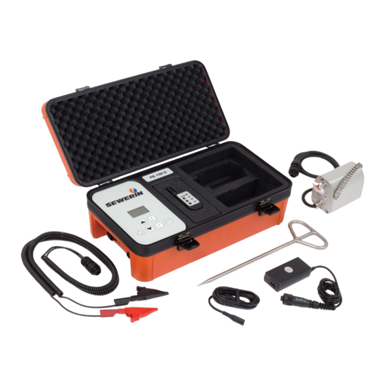
- Page 1 FERROPHON ® FG 155 C generator Striker and stopper Operating instructions...
- Page 2 FG 155 C generator Control panel Port for accessories Charging socket FG 155 C generator with open case Fig. 1: Fig. 2: Case with ground spike (view from below)
- Page 3 FG 155 C generator Display Arrow keys ● Up key ● Down key Frequency keys ON/OFF key Pulse button Fig. 3: Control panel Signal strength Frequency Signal strength Frequency State of charge Current State of charge Striker Signal behavior Signal behavior Fig.
- Page 4 Illustration of warnings in this document WARNING! Risk of personal injury. Could result in serious injury or death. CAUTION! Risk of personal injury. Could result in injury or health risk. NOTICE! Risk of damage to property.
-
Page 5: Table Of Contents
Introduction ................1 Information about this document ..........1 Purpose ..................1 Intended use ................1 Safety information ..............2 Product description ..............4 General ..................4 FG 155 C generator ..............5 2.2.1 Ports ..................5 2.2.2 Power supply ................5 2.2.3 Remote control ...............5 Optional accessories ..............6 2.3.1 Striker ..................6 2.3.2 Stopper ...................6... - Page 6 Energizing for acoustic location ..........19 3.3.1 Selecting the frequency ............19 3.3.2 Adjusting signal strength ............20 3.3.2.1 Signal strength of the striker ..........20 3.3.2.2 Signal strength of the stopper ...........20 3.3.3 Selecting the signal behavior (striker only) ......20 3.3.4 Energizing using a striker .............21 3.3.5 Energizing using a stopper ...........22 3.3.6...
-
Page 7: Introduction
Translations are produced to the best of our knowledge. The original German version is authoritative. Right of reproduction No part of this document may be edited, duplicated or circulated in any form without the express consent of Hermann Sewerin GmbH. Registered trademarks Registered trademarks are generally not indicated in this docu- ment. -
Page 8: Safety Information
● Use the product only as intended. ● Do not make any changes or modifications to the product un- less these have been expressly approved by Hermann Sew- erin GmbH. ● Only use accessories approved by Hermann Sewerin GmbH. ● Always observe the permitted operating and storage tempera- tures. ● Handle the product carefully and safely, both during transport and when working. - Page 9 ● When you are wearing headphones, you are not fully aware of ambient noise. Be especially vigilant, especially in environ- ments with an increased risk of accident (e.g. traffic). ● Do not use the product if it is damaged or faulty. ● Protect the ports and sockets against dirt, and electrical ports in particular against moisture. ● Proceed with extreme caution in the vicinity of electrical lines. 1 Introduction │ 3...
-
Page 10: Product Description
Product description General The FG 155 C generator is used to energize pipes for electro- magnetic or acoustic location. The generator is therefore also often referred to as the transmitter. The generator is permanently installed in a case. Overviews with the names of the generator parts can be found in the front cover (fig. 1 to fig. 3). -
Page 11: Fg 155 C Generator
Energizing for acoustic location Non-electroconductive pipelines can be made to vibrate by the FG 155 C generator with a connected striker or stopper. The acoustic signals generated in this way can be located acoustically using a suitable system (e.g. AQUAPHON system). FG 155 C generator Overviews with the names of the generator parts can be found in the front cover (fig. 1 to fig. 3). -
Page 12: Optional Accessories
Optional accessories 2.3.1 Striker The striker has a moving pin, which can be used to generate vi- brations on water or gas pipes. These vibrations allow the pipe to be located. You will find an overview with the names of the parts of the striker inside the back cover (fig. 15). 2.3.2 Stopper A stopper can generate vibrations on water mains which allow the pipe to be located. When water is withdrawn from a hydrant, the water column is set in motion. The stopper slows down the water column at in- tervals. -
Page 13: Frequencies
2.4.1.1 Frequencies The frequency measures how quickly the pulses acting on a pipe follow each other. Various preset frequencies are available for energizing (sec- tion 5.2.1). For direct energizing, individual frequencies can be set up in addition to the preset ones. Frequencies can be deactivated. Deactivating can be useful if, of all the preset and individual frequencies, only certain frequencies are needed for daily work. In the main view (fig. 4, pictured left) the number of selectable frequencies becomes smaller by deac- tivation. -
Page 14: Signal Strength
PIN-Code Fig. 6: PIN code view 2.4.1.2 Signal strength The signal strength is the intensity with which pulses affect a pipe. The signal strength corresponds to the output power of the gen- erator. The maximum output power depends on the signal be- havior: ● Continuous signal: max. 25 W ● Pulsed signal: max. -
Page 15: Signal Behavior
range ES1 . When the Notice symbol appears (fig. 7, pictured right), the generator operates in the ES2 range NOTICE! In the ES2 range, contact between metal parts (clamps, ground spike etc.) and body parts is painful but is not expected to cause injury. Nevertheless, the user is responsible for ensuring that persons or animals do not accidentally touch the metal parts. ●... -
Page 16: Acoustic Location
Signal Signal curve continuous signal pulsed Note: Operation with pulsed signal extends the operating time of the generator compared to operation with continuous signal. The signal behavior determines the maximum output power of the generator as well as the maximum current in the energized pipeline (section 2.4.1.2). -
Page 17: Signal Strength
2.4.2.2 Signal strength The signal strength is the intensity with which pulses affect a pipe. A high signal strength means high energy which helps with loca- tion e.g. across long distances or of thicker pipes. A low signal strength is often required if location has to take place close to the striker. This is because e.g. noise can be transmitted through the ground close to the striker. -
Page 18: Energizing Pipelines
Energizing pipelines WARNING! Danger of electrical shock! High voltages may be present at exposed parts of pipe- lines. ● Always observe the current rules when working near live pipelines. ● Do not touch any live parts (e. g. terminals, fittings, ground spike) during direct energizing. -
Page 19: Energizing For Electromagnetic Location
Energizing for electromagnetic location 3.2.1 Setting the frequency 3.2.1.1 Selecting the frequency The frequency for energizing must always be adapted to the local conditions. Note: The generator and receiver must operate at the same frequency. ● Adjust the frequency of the receiver to the frequency of the generator. -
Page 20: Adding A Frequency
● Press the On/Off key to complete the PIN code entry. The Frequency list 1 view (Fig 5, pictured left) appears. 3. Deactivate or activate the desired frequencies. a) Press the arrow keys to select a frequency. b) Press the pulse key to deactivate or activate the selected frequency. Frequency activated Frequency deactivated c) Press the On/Off key to apply the setting. 4. -
Page 21: Adjusting Signal Strength
● Press the On/Off key to complete the PIN code entry. The Frequency list 1 view (Fig 5, pictured left) appears. 3. Press the Down key until the Frequency list 3 view appears (Fig 5, pictured right). 4. Use the arrow keys to select a placeholder to be overwritten with an individual frequency. 5. Press the ON/OFF key. The placeholder is marked with Edit (fig. 8). -
Page 22: Selecting The Signal Behavior
3.2.3 Selecting the signal behavior On the generator it is possible to select between continuous sig- nal and pulsed signal. The generator is switched on. Either the cable set or no ac- cessory is connected. ● Press the pulse key to switch between continuous signal and pulsed signal. -
Page 23: Connecting With Ground Spike
● Always be especially careful when working with the ground spike, especially in the vicinity of other persons. ● Avoid dropping the ground spike. The ground spike is placed in the ground. SEWERIN recom- mends: The distance from the ground spike to the pipeline should be at least 3 m. -
Page 24: Energizing A Pipeline Indirectly
Fig. 10: Energizing with ground spike 1 Electrical connection to the pipeline to be located 2 Generator 3 Ground spike The generator is switched off. 1. Connect the cable set to the generator. 2. Insert the ground spike firmly into the ground. 3. Attach a clamp to the ground spike. 4. Attach the second clamp of the cable set to the exposed part of the pipeline to be energized. -
Page 25: Energizing For Acoustic Location
Fig. 11: Indirect energizing - alignment of the generator to the pipeline 1 Energized pipeline 2 Generator 3 Electromagnetic field The generator is switched off. 1. Place the generator as accurately as possible lengthways over the pipeline to be located. 2. Switch on the generator. In the main view, the Indirect energizing icon appears. 3. -
Page 26: Adjusting Signal Strength
3.3.2 Adjusting signal strength 3.3.2.1 Signal strength of the striker The signal strength of the striker can be changed in steps. The generator is switched on. The striker is connected. ● Press the Up key to increase the signal strength. ●... -
Page 27: Energizing Using A Striker
3.3.4 Energizing using a striker The striker can be used for gas and water pipes with an outer diameter of up to 4¾ inches. Fig. 12: Striker, attached to a house service connection 1. Attach the striker to the line. a) Place the fastening chain around the pipeline. b) Hook the fastening chain onto the striker. -
Page 28: Energizing Using A Stopper
3.3.5 Energizing using a stopper The stopper can be connected to: ● Above-ground hydrants ● Underground hydrants in conjunction with a standpipe Note: The section below explains how to use the stopper on an under- ground hydrant with standpipe. The stopper is connected directly to above-ground hydrants. -
Page 29: Using The Remote Control
4. Remove the stopper from the hydrant in the following order: a) Remove the stopper from the standpipe. b) Remove the standpipe from the hydrant. 5. Clean the stopper (section 4.2.2). 3.3.6 Using the remote control Note: The keys of the remote control are located below the black dots beside the symbols, not below the symbols. -
Page 30: Setting The Signal Strength (Striker Only)
Fig. 13: Energizing for acoustic location – main view when using the re- mote control (Symbol Pause) Starting a pause ● Press the pause key on the remote control. The Pause symbol appears on the display. Ending a pause ● Press the pause key on the remote control again. ●... -
Page 31: Maintenance
Maintenance Recharging the battery The battery of the generator must be charged when necessary. The typical charging time is less than 7 hours. The following is required for charging: ● AC/DC adapter L ● Vehicle cable L The AC/DC adapter and the vehicle cable are available to buy as accessories. -
Page 32: Care
● Always use a clean, soft cloth to clean the display surface. ● Never use cleaning agents containing aggressive constituents (e.g. acidic or abrasive constituents) to clean the display sur- face. SEWERIN recommends: Always remove significant contamina- tion immediately. 4.2.2 Cleaning the stopper The stopper must be thoroughly cleaned and dried after every use. - Page 33 NOTICE! Functional disturbances possible as a result of corrosion To prevent the corrosion of surfaces: ● Only reassemble the stopper when it is dry or immediately before next use. 1. Undo the screws on the front of the stopper using the Allen key provided.
-
Page 34: Water In The Case
● Always make sure the striker and stopper are clean and dry before storing. ● Store the striker in the case. Servicing SEWERIN recommends: Have the generator serviced regularly by SEWERIN Service or an authorized professional. Only regular servicing can ensure that the generator is always ready for use. 28 │ 4 Maintenance... -
Page 35: Troubleshooting
Troubleshooting 4.4.1 Generator Problem Possible cause Corrective action Generator cannot Power supply insuf- Recharge battery be switched on. ficient On/Off key pressed Press On/Off key for too briefly at least 1 s Energizing for Cable not electrically — electromagnet- conductive ic location is not Cable set defective Replace defective working cable set... -
Page 36: Stopper
5. Clean the stopper (section 4.2.2). 6. Reassemble the stopper. 7. Reconnect the stopper. 8. Start up the stopper. Note: If you cannot loosen the piston or if the problem recurs: ● Send the stopper to SEWERIN Service. 30 │ 4 Maintenance... -
Page 37: Appendix
Appendix Technical data Device data Dimensions (W × D × H) 19.7 × 10.3 × 7.5 inches Weight 18 lbs. 5 ounces Material ABS (housing) Certificates Certificates Marking Contains: FCC ID: OJM900MCA / IC: 5840A-900MCA Features Display FSTN, 2″, 240 × 128 pixels, LED backlight Processor DSP 16 bit Operation •... - Page 38 Data transmission (remote control) Transmission frequency 902 – 928 MHz Radio range 330 ft Communication radio Power 9.5 dBm Location Transmitting frequency electromagnetic location: • direct energizing: 512 Hz / 640 Hz / 1.100 kHz / 8.192 kHz / 9.950 kHz / 32.768 kHz / 41.666 kHz / 65.536 kHz / 83.078 kHz / 116.000 kHz Can also be set to any frequency between 200 Hz –...
-
Page 39: Preset Frequencies
Preset frequencies 5.2.1 Electromagnetic location Frequency Display in Frequency list Main view 512 Hz 512 Hz 512 Hz 640 Hz 640 Hz 640 Hz 1.100 kHz 1100 Hz 1.10 kHz 8.192 kHz 8192 Hz 8.19 kHz 9.950 kHz* 9950 Hz 9.95 kHz 32.768 kHz 32768 Hz... -
Page 40: Symbols On The Display
Accessories Part Order number COMBIPHON striker SA02-10000 COMBIPHON stopper SA03-10022 AC/DC adapter L LD26-10100 Vehicle cable L ZL05-10200 Other accessories are available for the FG 155 C generator. Please contact the SEWERIN sales department for further in- formation. 34 │ 5 Appendix... -
Page 41: Index
Index Acoustic location 10 Generator 5 frequency 33 cleaning 26 ports 5 power supply 5 switching off 12 Care 26 switching on 12 Carrying case 4 troubleshooting 29 Conductor loop 16 Ground spike 17 Connecting conductor loop 16 ground spike 17 Current 8 Indirect energizing 18 Direct energizing 16 Pause function 23... - Page 42 Signal behavior 9, 11, 20 selecting 16, 20 stopper 11 striker 11 Signal strength 8, 11 adjusting 15, 20 stopper 11 striker 11, 20, 24 Stopper 6 cleaning 26 loosening piston 30 signal strength 20 troubleshooting 30 Storage 28 Striker 6, 11 cleaning 26 signal behavior 20 signal strength 20, 24 troubleshooting 29 Symbols 34 Troubleshooting 29...
- Page 43 Connection cable Star knob Hook Fig. 15: Striker Cylinder on piston Signal strength controller Fig. 16: Stopper...
- Page 44 Fax.: +351 234 024 446 Tel.: +34 91 74807-57 www.sewerin.com Fax: +34 91 74807-58 info@sewerin.pt www.sewerin.com info@sewerin.es Sewerin Sp. z o.o. Sewerin Ltd. ul. Twórcza 79L / 1 Hertfordshire 03-289 Warszawa, Poland Tel.: +48 22 675 09 69 Phone: +44 1462-634363 Tel.:...
Need help?
Do you have a question about the FERROPHON FG 155 C and is the answer not in the manual?
Questions and answers