Table of Contents
Advertisement
Quick Links
Advertisement
Table of Contents

Related Manuals for Hobo MX800 Series


Summary of Contents for Hobo MX800 Series
- Page 1 HOBO MX800 Logger Series User Guide...
-
Page 2: Table Of Contents
Connect the Cable and Sensor to the Logger Calibrate the Sensor Mount and Deploy the Logger Configure and Start the HOBO MX802 Logger Using HOBOconnect 11 Download the Data Process the Data Download the HOBOconnect App and Access Logger Functions... - Page 3 Post-processing Data to Extract Other Parameters Maintain the Logger and Sensors Logger Events Pressure Sensor Drift Calibrate Sensors Conductivity Sensor Calibration DO Sensor Calibration Specifications HOBO MX801/802 Specifications CTD Sensor Specification CT Sensor Specification DO Sensor Specification U.S. and International Sales: 1-508-759-9500 www.onsetcomp.com...
-
Page 4: Introduction
Introduction The HOBO MX800 Series logger provides a single integrated platform for monitoring a range of crit- ical water parameters. The currently available sensors track multiple parameters and are available in the following combinations: conductivity, temperature, and depth (CTD) conductivity and temperature (CT) dissolved oxygen and temperature (DO) The loggers include built-in Bluetooth for quickly and wirelessly downloading data. -
Page 5: Hobo Mx801 Submersible Logger Quick Start Guide
HOBO MX801 Submersible Logger Quick Start Guide Overview The HOBO MX801 Submersible Logger is designed to be used with compatible HOBO W-Series sensors to log water parameters such as temperature, conductivity, depth and more. This logger must be deployed with the sensors attached, as it is not waterproof if sensors are not attached. -
Page 6: Calibrate The Sensor
This allows you to rotate the magnetic fob to where you can easily reach the magnet icons for activating logger functions. Download and Open HOBOconnect You need to use HOBOconnect with the HOBO MX Series loggers. To download HOBOconnect go www.onsetcomp.com/products/software/hoboconnect Calibrate the Sensor If you are using CTD, CT, or DO sensors, calibrate them in your office or lab before configuring the loggers for deployment. -
Page 7: Configure The Logger
(within 10 miles) to log barometric pressure changes. You can use a HOBO MX802 logger or a HOBO MX2001 logger to log barometric pressure. These require a cable and sensor to be attached to make them weatherproof, or use a termination plug (W-PLUG) on the MX802. -
Page 8: Download The Data
3. If you are logging water level, allow the MX801 logger time to reach temperature equilibrium and take a reference water level reading. Record this along with the time it was taken in your deployment notes. You will need this reference water level reading when you post-process the data in HOBOconnect. -
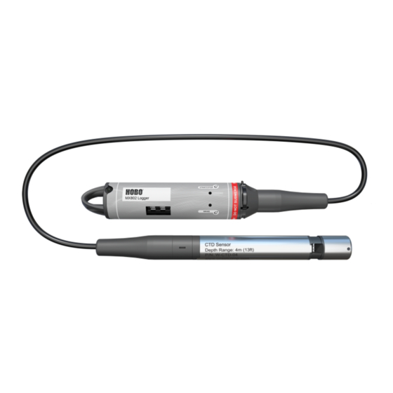
Page 9: Hobo Mx802 Direct Read Logger Quick Start Guide
HOBO MX802 Direct Read Logger Quick Start Guide Overview The HOBO MX802 Direct Read Logger is designed to be used with compatible HOBO W-Series sensors to log water parameters such as conductivity, temperature, depth and more. This logger is typically deployed with the sensor connected via direct-read cable. The sensor remains in the water while deployed and the logger is above the water for convenient wireless Bluetooth readout. - Page 10 3. Attach the tapered coupler over the connection between the cable and the logger. To do so, ensure that the magnetic fob is attached to one half of the tapered coupler. Snap one side of the coupler over the connection between the cable and the logger with the tapered end toward the cable.
-
Page 11: Calibrate The Sensor
This allows you to rotate the magnetic fob to where you can eas- ily reach the magnet icons for activating logger functions. Download and open HOBOconnect You need to use HOBOconnect with the HOBO MX Series loggers. To download HOBOconnect go www.onsetcomp.com/products/software/hoboconnect Calibrate the Sensor If you are using a CT, CTD, or DO sensor, calibrate it in your office or lab before configuring the log- gers for deployment. -
Page 12: Download The Data
Note: The logger is able to calculate and log certain parameters without need- ing to log the basic measurements used to get those parameters. For example you can log salinity without having to log electrical conductivity and tem- perature. However, it is often a good idea to log the basic measurements in case you need those later. -
Page 13: Download The Hoboconnect App And Access Logger Functions
Download the HOBOconnect App and Access Logger Functions Install the HOBOconnect app to connect to the logger. 1. Download HOBOconnect to a phone or tablet from the App Store® or Google Play™. 2. Download the app to a Windows computer from: www.onsetcomp.com/products/software/hoboconnect 3. - Page 14 Clear Alarms. Clears the current alarm. Add to Favorites allows you to mark the logger as one of your favorites. You can then filter the list of devices to show only loggers marked as favorites. Tap this icon to unmark the logger as a favorite. Lock the logger.
-
Page 15: Hobo Mx800 Logger Series User Guide
HOBO MX800 Logger Series User Guide Logger Components and Operation The following image shows the vent hole for the barometric sensor on the end of the MX802. Mounting loop: This cap is attached with screws to the logger body. Remove it to replace the bat- teries. -
Page 16: Configure Logger Operation
Conductivity Sensor: The conductivity sensor is visible at this break point in the sensor. Temperature Sensor: The temperature sensor is located about half way between the pressure sensor and the conductivity sensor. It is not visible. Pressure Sensor: The pressure sensor is located about one third of an inch (8mm) from the end of the sensor. - Page 17 then at another logger interval for the next time interval, for up to 8 time periods. It allows you to repeat a logging interval sequence or set a pause, which allows you to take a collection of readings at regular intervals. For example, you can have the logger log at 5 seconds for 1 minute, and then Pause logging for 5 minutes.
- Page 18 Set a Password You can create an encrypted password for the logger that is required if another device attempts to connect to it. This is recommended to ensure that a deployed logger is not mistakenly stopped or pur- posely altered by others. This password uses a proprietary encryption algorithm that changes with every connection.
- Page 19 To log statistics: 1. Select Fixed Logging Mode. 2. Turn Statistics On and select the statistics you want the logger to record at each logging inter- val: Maximum, Minimum, Average, and Standard Deviation (average is automatically enabled when selecting Standard Deviation). Statistics are logged for all enabled sensors. In addition, the more statistics you record, the shorter the logger duration and the more memory is required.
-
Page 20: Set Up Alarms
Burst Logging Interval H, M, S The rate of logging during burst logging. Logging Parameter Sets the threshold, below which logging happens at burst logging rate. High Sets the threshold, above which logging happens at burst logging rate. Notes: The high and low burst limits are checked at the burst logging interval rate whether the logger is in normal or burst condition. - Page 21 alarms should be active. In addition, each parameter that you are logging allows you to set alarm lim- its for it. Alarm Settings Show Visual Alarms Until Logger is Reconfigured The alarms continue until you reconfigure the logger. Sensors in Limits The alarms continue until the sensor reading falls within the set alarm limits.
-
Page 22: Turn Channels On And Off
The actual values for the high and low alarm limits are set to the closest value supported by the logger. For example, the closest value to 85°F that the logger can record is 84.990°F. In addition, alarms can trip or clear when the sensor reading is within the specified resolution specifications. -
Page 23: Mount And Deploy The Mx801 Logger
Mount and Deploy the MX801 Logger The submersible HOBO MX801 Logger is designed to be easy to deploy in many environments. It does not need a cable connecting it to a logger at the surface. The CTD sensor uses an absolute pressure sensor, so no vent tube is required. -
Page 24: Mount And Deploy The Mx802 Logger
Mount and Deploy the MX802 Logger The HOBO MX802 is weatherproof, but not waterproof. Mount the HOBO MX802 logger above the water so that it can log barometric pressure. There is a vent with a hydrophobic membrane that allows the logger to sense barometric pressure while keeping water out. - Page 25 CAP-01) to suspend the logger and sensor in the well. If your well must remain sealed and there is no way to avoid a continuous saturated environment, use non-vented water level loggers, such as the HOBO U20 or U20L water level loggers. Other Well Mounting Considerations...
- Page 26 Be very careful not to exceed the burst pressure for the sensor. The pressure sensor will burst if the maximum depth is exceeded (see HOBO MX801/802 Specifications). The sensor should be positioned at a depth where it will remain in the water for the duration of the deployment, but not exceed the rated bursting depth.
-
Page 27: Take Reference Water Level Measurements (Mx801 And Mx802)
If the cable is too long, loop the cable and secure the cable with 3 or 4 cable ties to ensure the loop does not slip. The looped cable should be tight enough that the cable can be easily pulled out of the well if necessary, but it must not bend the cable any tighter than a 1.25 cm (0.5 inch) radius to prevent damage to the cable. - Page 28 If the water level surface is below the reference point as shown below, enter the reference water level in the app as a negative number. If the water level surface is above the reference point as shown below, enter the reference water level in the app as a positive number.
-
Page 29: Download Data From The Logger
3. Once the download is complete, tap Done to return to the previous page or tap Export and Share to save the file in the specified format. You can also upload data automatically to HOBOlink, Onset’s web-based software, using the HOBO- connect app. For details, see the... - Page 30 Water Density Several selections for water density, including an option to manually enter water density. Reference Water Level In general, you should use a reference water level. Enter the reference water level measurement that you recorded during the deployment and select the closest time to when that was taken.
-
Page 31: Maintain The Logger And Sensors
Maintain the Logger and Sensors Clean the Logger Periodically inspect the logger for fouling. To clean the logger housing, rinse the logger in warm water, making sure that a sensor or cable is attached. With the MX802 logger, avoid getting water in the vent for the barometric pressure sensor. - Page 32 Change the Sensor on the MX801 To change the sensor attached to the MX801 logger: 1. Stop the logger if it is still running. 2. Download any data from the logger. 3. Using the 3/32" allen wrench included with your logger, remove the tapered coupler from the logger and detach the sensor by pulling it straight out.
-
Page 33: Logger Events
To install the copper guard: 1. Slide one of the o-rings so that it is above the conductivity sensor. 2. Then slide the copper guard over the sensor. 3. Position the guard so the holes are over the conductivity sensor. 4. -
Page 34: Pressure Sensor Drift
Internal Event Name Definition Host Connect The logger was connected to the mobile device. Started The logger started logging. Stopped The logger stopped logging. Alarm Tripped/Cleared An alarm event has occurred because the reading was outside the alarm limits or back within range. Note: Although the reading may have returned to a nor- mal range during logging, an alarm cleared event will not be logged if the logger was set up to maintain alarms until reconfigured. -
Page 35: Calibrate Sensors
Compare the reference water level reading you took at the end of the deployment with the logged value that is closest to that in time. If the two readings are close, there is not much drift. If there are differences between these two figures, you must investigate further. The logger may have exper- ienced sensor drift, a shift in the logger position during its deployment, or a difference in how you took the readings. - Page 36 5. Enter the calibration screen in HOBOconnect (if you're not already there). To do so, move the magnet to the Wake icon on the logger. When you see the logger tile appear in HOBO- connect, click that tile. If HOBOconnect prompts you to calibrate the logger, click Yes. Other- wise, click Conductivity Calibration.
- Page 37 8. To add another calibration point, repeat the above steps, staying in the HOBOconnect cal- ibration loop. 9. Once you have entered the desired number of calibration points, save your calibration. 10. When done, rinse the sensor with tap and DI water (deionized water) to prevent salt from hardening on the electrodes.
- Page 38 Temperature Coefficient = ((80,000 – 72,900) / 80,000) / (25 – 20) = 8.875% / 5°C = 1.78%/°C The result is that the temperature coefficient is 1.78%/°C. U.S. and International Sales: 1-508-759-9500 www.onsetcomp.com...
-
Page 39: Do Sensor Calibration
DO Sensor Calibration In development. U.S. and International Sales: 1-508-759-9500 www.onsetcomp.com... -
Page 40: Specifications
Specifications HOBO MX801/802 Specifications Operating Range -40° to 50°C (-40° to 122°F), cannot be frozen in ice Radio Power 1 mW (0 dBm) Transmission Range Approximately 30.5 m (100 ft) line-of-sight Wireless Data Standard Bluetooth 5 Number of sensors that... - Page 41 Memory 730,000 measurements, divided between channels (4 Mbyte memory) Data Download Time (with Full memory: Approximately 3.5 minutes Bluetooth 5+ devices) 120,000 measurements: 1 minute May take longer the further the device is from the logger. Weight MX801: Logger only including batteries, 213g (7.51 oz) MX802: Logger only including batteries, 215g (7.58 oz) Tapered collar for MX801 and MX802: 11g (0.39 oz) 2m Cable: 153g (5.40 oz)
- Page 42 System Water Level Accuracy equals the sum of the Baro- metric Water Level Accuracy plus the selected CTD sensor Water Level Accuracy. MX800 Series Logger The following is a technical drawing of the logger with dimensions.
-
Page 43: Ctd Sensor Specification
CTD Sensor Specification Conductivity Measurements Measurement Range Electrical conductivity and specific conductance: 0 to 100,000 µS/cm Salinity using PSS-78: 2 to 42 PSU Total Dissolved Solids (TDS): 0 to 100,000 mg/L Calibrated Range Electrical conductivity: 50 to 80,000 µS/cm 5° to 35°C (41° to 95°F) Accuracy Conductivity: +/-2% of reading or 15 µS/cm, whichever is greater Salinity: +/-2% of reading or 0.1 PSU, whichever is greater... - Page 44 Absolute Pressure and Water Level Measurements W-CTD-02 Range 0 to 400 kPa (0 to 58 psia); approximately 0 to 30.6 m (0 to 100 ft) of water depth at sea level, or 0 to 33.6 m (0 to 111 ft) of water at 3,000 m (10,000 ft) of altitude Factory Calibrated Range 69 to 400 kPa (10 to 58 psia), 0°...
- Page 45 Absolute Pressure and Water Level Measurements W-CTD-04 Range 0 to 145 kPa (0 to 21 psia); approximately 0 to 4 m (0 to 13 ft) of water depth at sea level, or 0 to 7 m (0 to 23 ft) of water at 3,000 m (10,000 ft) of altitude Factory Calibrated Range 69 to 145 kPa (10 to 21 psia), 0°...
- Page 46 Wetted Materials Passivated 316 Stainless steel housing rated for use in saltwater, Viton and Buna-N O-rings, PET sensor connector Depth sensor: ceramic Conductivity sensor: PET, platinum plating on electrodes Note: Sensor should be mounted so that it is not in contact with other metals Environmental Rating IP68;...
- Page 47 CTD Sensor The following is a technical drawing of the CTD sensor with dimensions. U.S. and International Sales: 1-508-759-9500 www.onsetcomp.com...
-
Page 48: Ct Sensor Specification
CT Sensor Specification Conductivity Measurements Measurement Range Electrical conductivity and specific conductance: 0 to 100,000 µS/cm Salinity using PSS-78: 2 to 42 PSU Total Dissolved Solids (TDS): 0 to 100,000 mg/L Calibration Range Electrical conductivity: 50 to 80,000 µS/cm 5° to 35°C (41° to 95°F) Accuracy Conductivity: +/-2% or 15 µS/cm whichever is greater Salinity: +/-2% of reading or 0.1 PSU, whichever is greater... - Page 49 Wetted Materials Passivated 316 Stainless steel housing rated for use in saltwater, Viton and Buna-N O-rings, PET sensor connector Conductivity sensor: PET, platinum plating on electrodes Note: Sensor should be mounted so that it is not in contact with other metals Environmental Rating IP68;...
-
Page 50: Do Sensor Specification
DO Sensor Specification Dissolved Oxygen Sensor Type Optical (dynamic luminescence quenching) Measurement Range 0 to 60 mg/L; 0-600% Saturation Accuracy Out-of-box: ±0.2 mg/L over the range of 0 to 20 mg/L; ±4% over the range of 20 to 60 mg/L With user calibration: ±0.1 mg/L over the range of 0 to 20 mg/L;... - Page 51 Wetted Materials Black Delrin®, PVC, EPDM o-rings, rated for saltwater use SIze To be determined. Weight To be determined. Markings The CE Marking identifies this product as complying with all relevant directives in the European Union (EU). U.S. and International Sales: 1-508-759-9500 www.onsetcomp.com...
Need help?
Do you have a question about the MX800 Series and is the answer not in the manual?
Questions and answers