
Related Manuals for NexAIoT NISE 53


Summary of Contents for NexAIoT NISE 53
- Page 1 NexAIoT Co., Ltd. IoT Automation Solutions Business Group Fan-less Computer NISE 53 User Manual NexAIoT Co., Ltd. www.nexaiot.com Published October 2023...
-
Page 2: Table Of Contents
Functional Ground Isolation ..............7 Declaration of Conformity ..............iv Jumper Settings ..................8 RoHS Compliance ................... v Locations of the Jumpers and Connectors for NISE 53 ......9 Warranty and RMA ................vi Connector Pin Definitions ..............10 Installation Recommendations ..............vii External I/O Interfaces ................10 Safety Information ................viii... - Page 3 Appendix B: Watchdog Timer Setting Front accessible M.2 Key B ..............30 Internal M.2 Key B ................32 Appendix C: Power Consumption Installing a SIM Card ................33 Installing an Antenna ................35 Copyright © 2023 NexAIoT Co., Ltd. All Rights Reserved. NISE 53 User Manual...
-
Page 4: Preface
Acknowledgements The product(s) described in this manual complies with all applicable NISE 53 is a trademark of NexAIoT Co., Ltd. All other product names European Union (CE) directives if it has a CE marking. For computer systems mentioned herein are registered trademarks of their respective owners. -
Page 5: Rohs Compliance
(Cr6+) < 0.1% or 1,000ppm, Polybrominated biphenyls (PBB) < 0.1% or 1,000ppm, and Polybrominated diphenyl Ethers (PBDE) < 0.1% or 1,000ppm. In order to meet the RoHS compliant directives, NexAIoT has established an engineering and manufacturing task force to implement the introduction of green products. -
Page 6: Warranty And Rma
“NexAIoT RMA Service Form” for the RMA number apply process. ▪ If RMA goods can not be repaired, NexAIoT will return it to the customer without any charge. ▪ Customers can send back the faulty products with or without accessories (manuals, cable, etc.) and any components from the card, such as CPU... -
Page 7: Installation Recommendations
Using your fingers can disconnect most of the connections. It is recommended that you do not use needle-nose pliers to disconnect connections as these can damage the soft metal or plastic parts of the connectors. Copyright © 2023 NexAIoT Co., Ltd. All Rights Reserved. NISE 53 User Manual... -
Page 8: Safety Information
Discard used batteries according to the manufacturer’s instructions. ▪ This product is intended to be supplied by an approved power adapter, rated 12Vdc, 5A or 24Vdc, 2.5A minimum and Tma 55 degree Celsius. If further assistance is needed, please contact NexAIoT for further information. viii Copyright ©... -
Page 9: Safety Precautions
ACCORDING TO THE MANUFACTURER’S INSTRUCTIONS. 11. If the equipment is not used for a long time, disconnect it from the power source to avoid damage by transient overvoltage. Copyright © 2023 NexAIoT Co., Ltd. All Rights Reserved. NISE 53 User Manual... -
Page 10: Technical Support And Assistance
Preface Technical Support and Assistance Conventions Used in this Manual 1. For the most updated information of NexAIoT products, visit NexAIoT’s Warning: website at www.nexaiot.com. Information about certain situations, which if not observed, can cause personal injury. This will prevent injury to yourself 2. -
Page 11: Global Service Contact Information
16F, No.250, Sec. 2, Chongde Rd., Tel: +886-2-8976-3077 Tel: +886-2-8226-7786 Beitun District, Email: sales@diviotec.com Fax: +886-2-8226-7782 Taichung City, 406, Taiwan, R.O.C. www.diviotec.com Email: services@tmrtek.com Tel: +886-4-2249-1179 www.tmrtek.com Fax: +886-4-2249-1172 Email: jacobhuang@nexaiot.com www.nexaiot.com Copyright © 2023 NexAIoT Co., Ltd. All Rights Reserved. NISE 53 User Manual... - Page 12 GanKeng Community, Buji Street, 4-11-5, Shiba Minato-ku, LongGang District, Tokyo, 108-0014, Japan ShenZhen, 518112, China Tel: +81-3-5419-7830 Tel: +86-755-8364-7768 Fax: +81-3-5419-7832 Fax: +86-755-8364-7738 Email: sales@nexcom-jp.com Email: steveyang@nexcom.com.tw www.nexcom-jp.com www.nexcom.cn Copyright © 2023 NexAIoT Co., Ltd. All Rights Reserved. NISE 53 User Manual...
-
Page 13: Package Contents
Preface Package Contents Before continuing, verify that the package that you received is complete. Your NISE 53 package should have all the items listed in the following table. Item Part Number Description 7400060054X00 POWER ADAPTER LITEON:HA-1600-24E5 5061711760X00 MINI PCI-E BRACKET FOR NISE106 SERIES VER:A ASDA... -
Page 14: Ordering Information
Preface Ordering Information The following information below provides ordering information for NISE 53. NISE 53-E01 (P/N: 10J00005300X0) - Intel Celeron J6413 processor quad core fanless system with 60W AC ® ® to DC power adapter, w/o power cord NISE 53-E02 (P/N: 10J00005301X0) -
Page 15: Chapter 1: Product Introduction
▪ 1 x Front accessible M.2 Key B ▪ 1 x Internal M.2 Key B Rear ▪ Support operating temperature from -10°C to 60°C ▪ Support +12V/24V DC input; support ATX power mode Copyright © 2023 NexAIoT Co., Ltd. All Rights Reserved. NISE 53 User Manual... -
Page 16: Hardware Specifications
– COM2: RS232/485, only support TX/RX/CTS/RTS Dimensions ▪ 1 x 3-pin terminal block, support +12/+24V DC input ▪ 186mm (W) x 150mm (D) x 26mm (H) Copyright © 2023 NexAIoT Co., Ltd. All Rights Reserved. NISE 53 User Manual... - Page 17 ▪ Vibration protection with M.2/ mSATA condition – Random: 2Grms @ 5~500 Hz, IEC60068-2-64 – Sinusoidal: 2Grms @ 5~500 Hz, IEC60068-2-6 Certifications ▪ CE ▪ FCC Class A Copyright © 2023 NexAIoT Co., Ltd. All Rights Reserved. NISE 53 User Manual...
-
Page 18: Knowing Your Nise 53
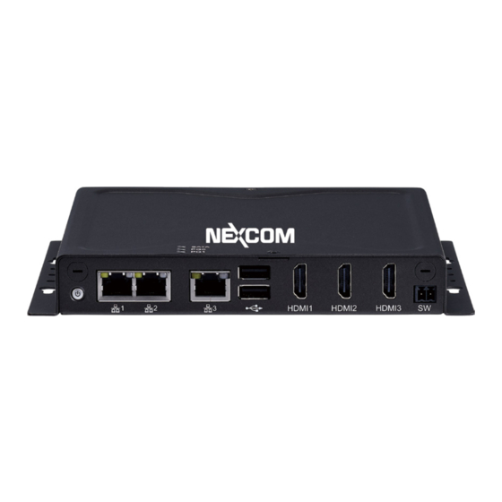
USB 2.0 Connect the system with USB 2.0/1.1 devices. HDMI Ports Connect with HDMI interface displays. Remote On/Off Switch Connect a remote to power on/off the system. Copyright © 2023 NexAIoT Co., Ltd. All Rights Reserved. NISE 53 User Manual... -
Page 19: Rear Panel
Use the provided power adapter only from the package, and connect it to the DC side (3-pin phoenix connector) of the system before connecting it to the AC side. Copyright © 2023 NexAIoT Co., Ltd. All Rights Reserved. NISE 53 User Manual... -
Page 20: Mechanical Dimensions
Chapter 1: Product Introduction Mechanical Dimensions Copyright © 2023 NexAIoT Co., Ltd. All Rights Reserved. NISE 53 User Manual... -
Page 21: Chapter 2: Jumpers And Connectors
Chapter 2: Jumpers and Connectors 2: J haPter umPers and onneCtors This chapter describes how to set the jumpers and connectors on the NISE 53 dry environments. A grounding strap is warranted whenever danger of motherboard. static electricity exists. Before You Begin Precautions ▪... -
Page 22: Chassis Ground Isolation
Round Head Screw Long Fei: p6#32T Nylok P6#32T Outer Teeth connect it to the DC side (3-pin phoenix connector) of the system Washer Nylok before connecting it to the AC side. Copyright © 2023 NexAIoT Co., Ltd. All Rights Reserved. NISE 53 User Manual... -
Page 23: Jumper Settings
Refer to the illustrations below for examples of what the 2-pin and 3-pin jumpers look like when they are short (on) and open (off). Two-Pin Jumpers: Open (Left) and Short (Right) Three-Pin Jumpers: Pins 1 and 2 are Short Copyright © 2023 NexAIoT Co., Ltd. All Rights Reserved. NISE 53 User Manual... -
Page 24: Locations Of The Jumpers And Connectors For Nise 53
Locations of the Jumpers and Connectors for NISE 53 The following figures show the motherboard used in the NISE 53 series, and indicate the locations of the jumpers and connectors. Refer to this chapter for detailed pin settings and definitions of the connectors marked in pink on this figure. -
Page 25: Connector Pin Definitions
RS485 DATA- COM TXD COM CTS RS485 DATA+ CHASIS_GND CHASIS_GND CHASIS_GND CHASIS_GND RS485 Full Duplex Definition Definition RS485 RX+ RS485 TX- RS485 TX+ RS485 RX- CHASIS_GND CHASIS_GND Copyright © 2023 NexAIoT Co., Ltd. All Rights Reserved. NISE 53 User Manual... -
Page 26: Hdmi Port
Connector location: J1 Definition Definition Definition HDMI_D2+ AGND VCCIN AGND HDMI_CLK- HDMI_D2- Chassis GND HDMI_D1+ AGND DDC_SCL HDMI_D1- DDC_SDA HDMI_D0+ AGND HDMI_D0- HDMI_HPD HDMI_CLK+ CHASIS_GND CHASIS_GND CHASIS_GND CHASIS_GND Copyright © 2023 NexAIoT Co., Ltd. All Rights Reserved. NISE 53 User Manual... -
Page 27: Remote Power On/Off Thr
Chapter 2: Jumpers and Connectors Remote Power On/Off THR Connector location: JP3 Definition PWRBTN#_J Copyright © 2023 NexAIoT Co., Ltd. All Rights Reserved. NISE 53 User Manual... -
Page 28: Lan Ports
Always On Green LAN1MDI0N LAN2MDI0N LAN1MDI1P LAN2MDI1P LAN1MDI1N LAN2MDI1N LAN1TVCC1 LAN2TVCC1 LAN1MDI2P LAN2MDI2P LAN1MDI2N LAN2MDI2N LAN1MDI3P LAN2MDI3P LAN1MDI3N LAN2MDI3N LAN1LINK1000L LAN2LINK1000L LAN1LINK100L1 LAN2LINK100L1 LAN1LEDACTL LAN2LEDACTL LAN1LEDPWR LAN2LEDPWR CHASIS_GND CHASIS_GND Copyright © 2023 NexAIoT Co., Ltd. All Rights Reserved. NISE 53 User Manual... -
Page 29: Lan Port
Link LED (Right) RGM1MDIP[0] RGM1MDIN[3] 1000 Always On Green RGM1MDIN[0] RGM1LED0 Blinking Yellow Always On Orange RGM1MDIP[1] RGM1LED0100 RGM1MDIN[1] RGM1LED1 RGM1VCC1 RGM1LED1ACT RGM1MDIP[2] RGM1MDIN[2] CHASIS_GND RGM1MDIP[3] CHASIS_GND Copyright © 2023 NexAIoT Co., Ltd. All Rights Reserved. NISE 53 User Manual... -
Page 30: Led Indicators
ATX_PBT ATX_PBT Definition Definition PWRLED_N N16937976 LED1 330 ohm pull up 3.3V SATALED LED2 330 ohm pull up 3.3V GPOLED1 LED3 330 ohm pull up 3.3V GPOLED2 Copyright © 2023 NexAIoT Co., Ltd. All Rights Reserved. NISE 53 User Manual... -
Page 31: Usb3.0 Connectors
Definition +5VSB +5VSB USB2_N2 USB2_N3 USB2_N0 USB2_N1 USB2_P2 USB2_P3 USB2_P0 USB2_P1 USB3_RXN0 USB3_RXN1 CHASIS_GND CHASIS_GND USB3_RXP0 USB3_RXP1 CHASIS_GND CHASIS_GND USB3_TXN0 USB3_TXN1 USB3_TXP0 USB3_TXP1 CHASIS_GND CHASIS_GND CHASIS_GND CHASIS_GND Copyright © 2023 NexAIoT Co., Ltd. All Rights Reserved. NISE 53 User Manual... -
Page 32: Internal Connectors - Dip Switch
Status Clean CMOS Normal (Default) ATX Mode: Press the power button to switch on when power is available. AT Mode: Direct power on when power is available. Copyright © 2023 NexAIoT Co., Ltd. All Rights Reserved. NISE 53 User Manual... -
Page 33: Internal Connectors - Header
Chapter 2: Jumpers and Connectors Internal Connectors - Header RTC Battery Connector location: BAT1 Definition Definition 3V_BAT1 Copyright © 2023 NexAIoT Co., Ltd. All Rights Reserved. NISE 53 User Manual... -
Page 34: M.2 Key B Connector
M.2 Key B Connector Connector location: CN1 Definition Definition Definition Definition M2BCONFIG3 M2LTEPWR M2BCONFIG0 M2LTEPWR LTEPEWAKE2 S_GP42 I_USB2P0 S_GP43 I_USB2N0 I_USB3RXN2 UIM_RESET M2REFCLK- I_USB3RXP2 UIM_CLK UIM_DATA I_USB3TXN2 UIM_PWR I_USB3TXP2 Copyright © 2023 NexAIoT Co., Ltd. All Rights Reserved. NISE 53 User Manual... - Page 35 Chapter 2: Jumpers and Connectors Definition Definition Definition Definition I_PCIERXN4 I_PCIERXP4 I_PCIETXN4 M2LTERSTL M2B_SUSCLK I_PCIETXP4 LTEPERSTL M2BCONFIG1 M2LTEPWR M2LTEPWR M2REFCLKN LTEPEWAKE1 M2LTEPWR M2REFCLKP M2BCONFIG2 Copyright © 2023 NexAIoT Co., Ltd. All Rights Reserved. NISE 53 User Manual...
- Page 36 M.2 Key B Connector Connector location: CN2 Definition Definition Definition Definition M2BCONFIG3 M2LTEPWR M2BCONFIG0 M2LTEPWR LTEPEWAKE2 S_GP42 I_USB2P2 S_GP43 I_USB2N2 I_PCIERXN3 UIM_RESET M2REFCLK- I_PCIERXP3 UIM_CLK UIM_DATA I_PCIETXN3 UIM_PWR I_PCIETXP3 Copyright © 2023 NexAIoT Co., Ltd. All Rights Reserved. NISE 53 User Manual...
- Page 37 Chapter 2: Jumpers and Connectors Definition Definition Definition Definition PCIESATARP2 PCIESATARN2 PCIESATATN2 M2LTERSTL M2B_SUSCLK PCIESATATP2 LTEPERSTL M2BCONFIG1 M2LTEPWR M2LTEPWR M2REFCLKN LTEPEWAKE1 M2LTEPWR M2REFCLKP M2BCONFIG2 Copyright © 2023 NexAIoT Co., Ltd. All Rights Reserved. NISE 53 User Manual...
-
Page 38: Mini Pcie Connector
I_WAKEL 3VSB_MINILTE PCIESATATN I_SMB3P3DATA PCIESATATP 1V5_MINI I_USB2N1 I_PCIECLKREQL0 UIM_PWR I_USB2P1 UIM_DATA 3VSB_MINILTE I_PCIECLKOUTN0 UIM_CLK 3VSB_MINILTE I_PCIECLKOUTP0 UIM_RESET UIM_VPP 1V5_MINI LTEDISL LTERSTL 3VSB_MINILTE PCIESATARP 3VSB_MINILTE PCIESATARN 1V5_MINI I_SMB3P3CLK Copyright © 2023 NexAIoT Co., Ltd. All Rights Reserved. NISE 53 User Manual... -
Page 39: Com Port Header
Chapter 2: Jumpers and Connectors COM Port Header UART4/I2C Header Connector location: COM1 Connector location: COM2 Definition Definition COM4DCDL VCC5 COM4RXD COM4TXD COM4DTRL COM4DSRL UART3_TXD COM4RTSL UART3_RXD COM4CTSL COM4RIL I2C_SCL I2C_SDA Copyright © 2023 NexAIoT Co., Ltd. All Rights Reserved. NISE 53 User Manual... -
Page 40: De1 Connector
Chapter 2: Jumpers and Connectors DE1 Connector Connector location: DE1 Definition I_PLTRSTL I_ESPICLK I_ESPICS0L I_ESPIIO3 I_ESPIIO2 I_ESPIIO1 I_ESPIIO0 I_ESPIRSTL 3VSB Copyright © 2023 NexAIoT Co., Ltd. All Rights Reserved. NISE 53 User Manual... -
Page 41: Ddr4 So-Dimm Slot
DDR1_DQSP1 DDR1_DQ7 DDR1_DQ4 DDR1_DQ12 DDR1_DQ11 DDR1_DQSN0 CHBDM DDR1_DQ8 DDR1_DQ15 DDR1_DQSP0 DDR1_DQ0 DDR1_DQ18 DDR1_DQ17 DDR1_DQ5 DDR1_DQ2 DDR1_DQ16 DDR1_DQ20 DDR1_DQ3 DDR1_DQ14 DDR1_DQSN2 CHBDM DDR1_DQ10 DDR1_DQSP2 DDR1_DQ13 DDR1_DQ19 DDR1_DQ9 DDR1_DQ22 Copyright © 2023 NexAIoT Co., Ltd. All Rights Reserved. NISE 53 User Manual... - Page 42 DDR1_A0 DDR1_DQSN8 CHBDM8 DDR1_BA1 DDR1_A10 DDR1_DQSP8 VDDQ VDDQ DDR1_CB6 DDR1_CSL0 DDR1_BA0 DDR1_CB2 DDR1_WEL DDR1_RASL DDR1_CB7 VDDQ VDDQ DDR1_CB3 DDR1_ODT0 DDR1_CASL DDR_RSTL DDR1_CSL1 DDR1_A13 DDR1_CKE0 DDR1_CKE1 VDDQ VDDQ Copyright © 2023 NexAIoT Co., Ltd. All Rights Reserved. NISE 53 User Manual...
- Page 43 DDR1_DQ39 DDR1_DQSN7 DDR1_DQ41 CHBDM DDR1_DQSP7 DDR1_DQ47 DDR1_DQ42 DDR1_DQ59 DDR1_DQ56 DDR1_DQ43 DDR1_DQSN5 DDR1_DQ63 DDR1_DQ60 CHBDM DDR1_DQSP5 MEMSCL MEMSDA DDR1_DQ45 DDR1_DQ44 VCC3 AD1SA0 VDDQ_VTT DDR1_DQ46 DDR1_DQ40 AD1SA1 DDR1_DQ49 DDR1_DQ53 Copyright © 2023 NexAIoT Co., Ltd. All Rights Reserved. NISE 53 User Manual...
-
Page 44: Gpio Header
Flash BIOS Pin Header Connector location: GPIO1 Connector location: JFW1 Definition Definition Definition Definition GPIO_PWR VSPI GPO0_OUT GPI0_IN BIOSSPICSL0 BIOSSPICLK GPO1_OUT GPI1_IN BIOSSPISO BIOSSPISI GPO2_OUT GPI2_IN GPO3_OUT GPI3_IN Copyright © 2023 NexAIoT Co., Ltd. All Rights Reserved. NISE 53 User Manual... -
Page 45: Reset Pin Header
Chapter 2: Jumpers and Connectors Reset Pin Header Nano SIM Connector Connector location: JP1 Connector location: SIM1 Description Definition SYSRESETN UIM_PWR UIM_RESET UIM_SIM_CLK UIM_VPP UIM_DATA Copyright © 2023 NexAIoT Co., Ltd. All Rights Reserved. NISE 53 User Manual... -
Page 46: Chapter 3: System Setup
Remove the six mounting screws around the chassis cover. There are two screws each on the top and on the sides. With the screws removed, lift up the cover and remove it from the chassis. Copyright © 2023 NexAIoT Co., Ltd. All Rights Reserved. NISE 53 User Manual... -
Page 47: Installing A So-Dimm Memory Module
Push the module down until the clips on both sides of the socket lock into position. The ejector tabs at the ends of the socket will automatically snap into the locked position to hold the module in place. Copyright © 2023 NexAIoT Co., Ltd. All Rights Reserved. NISE 53 User Manual... - Page 48 ▪ Optional Thermal Pad E-LIN 60x20x10mm (P/N: 5060200678X00) Thermal Pad Copyright © 2023 NexAIoT Co., Ltd. All Rights Reserved. NISE 53 User Manual...
-
Page 49: Installing A Installing A Mini Pcie Card (Full-Size)
Insert the module into the mini-PCIe slot at a 45-degree angle until the gold-plated connector on the edge of the module completely disappears into the slot. Mini-PCIe Card Copyright © 2023 NexAIoT Co., Ltd. All Rights Reserved. NISE 53 User Manual... - Page 50 ▪ Optional Thermal Pad E-LIN 30x20x12mm (P/N: 5060200675X00) Thermal Pad Copyright © 2023 NexAIoT Co., Ltd. All Rights Reserved. NISE 53 User Manual...
-
Page 51: Installing An M.2 Key B Module
Front accessible M.2 Key B Unscrew the M.2 bay tray on the front panel and remove it from the device. Secure the M.2 module to the bay tray with a screw. Copyright © 2023 NexAIoT Co., Ltd. All Rights Reserved. NISE 53 User Manual... - Page 52 Chapter 3: System Setup Reinstall the bay tray in the device and secure it with the screw you removed in step Copyright © 2023 NexAIoT Co., Ltd. All Rights Reserved. NISE 53 User Manual...
-
Page 53: Internal M.2 Key B
M.2 length, using a screwdriver. Standoff 3052 3042/2242 Fasten a screw into the M.2 standoff mounting hole to secure the module in place. Copyright © 2023 NexAIoT Co., Ltd. All Rights Reserved. NISE 53 User Manual... -
Page 54: Installing A Sim Card
Locate the SIM card holder on the motherboard. Flip up the SIM Card Slot cover and place the SIM card onto the holder. SIM Card Cover SIM Card Copyright © 2023 NexAIoT Co., Ltd. All Rights Reserved. NISE 53 User Manual... - Page 55 Chapter 3: System Setup Close the cover and secure it to the original position. Copyright © 2023 NexAIoT Co., Ltd. All Rights Reserved. NISE 53 User Manual...
-
Page 56: Installing An Antenna
Please remove the gaskets (ring 1 and ring 2) on the SMA Remove the antenna hole cover located on the front and rear panel. antenna jack first. Ring 2 Ring 1 Ring 1 Ring 2 Copyright © 2023 NexAIoT Co., Ltd. All Rights Reserved. NISE 53 User Manual... - Page 57 Insert the SMA antenna jack end of the cable through the antenna hole, and insert the 2 rings (ring 1 and ring 2) and two washers back to Gasket and washer installation sequence. the antenna jack. Installation Sequence Copyright © 2023 NexAIoT Co., Ltd. All Rights Reserved. NISE 53 User Manual...
- Page 58 RF Cable Side A facing inwards and each other Side A Side B Connect the external antenna to the antenna jack. Copyright © 2023 NexAIoT Co., Ltd. All Rights Reserved. NISE 53 User Manual...
-
Page 59: Chapter 4: Bios Setup
This chapter describes how to use the BIOS setup program for NISE 53. The The settings made in the setup program affect how the computer performs. BIOS screens provided in this chapter are for reference only and may change It is important, therefore, first to try to understand all the setup options, and if the BIOS is updated in the future. -
Page 60: Default Configuration
Powering on the computer and immediately pressing allows you to enter Setup. Load optimized default values. Saves and exits the Setup program. Press <Enter> to enter the highlighted sub-menu. Copyright © 2023 NexAIoT Co., Ltd. All Rights Reserved. NISE 53 User Manual... - Page 61 When “” appears on the left of a particular field, it indicates that a submenu which contains additional options are available for that field. To display the submenu, move the highlight to that field and press Copyright © 2023 NexAIoT Co., Ltd. All Rights Reserved. NISE 53 User Manual...
-
Page 62: Bios Setup Utility
Memory RC Version 0.0.4.104 F3: Optimized Defaults Total Memory 16384 MB F4: Save & Exit Memory Data Rate 3200MTPS ESC: Exit PCH Information Version 2.21.1278. Copyright (C) 2023 AMI Copyright © 2023 NexAIoT Co., Ltd. All Rights Reserved. NISE 53 User Manual... -
Page 63: Advanced
Vanderpool Technology. F1: General Help F2: Previous Values F3: Optimized Defaults F4: Save & Exit ESC: Exit Version 2.21.1278. Copyright (C) 2023 AMI Copyright © 2023 NexAIoT Co., Ltd. All Rights Reserved. NISE 53 User Manual... - Page 64 TPM Device Selection Use to select a TPM device. The options are PTT and dTPM. Warning! PTT/dTPM will be disabled and all data saved on it will be lost. Copyright © 2023 NexAIoT Co., Ltd. All Rights Reserved. NISE 53 User Manual...
- Page 65 TPM 2.0 devices if not found, and TPM 1.2 devices will be Enable or disable SHA-1 PCR Bank. enumerated. SHA256 PCR Bank Enable or disable SHA256 PCR Bank. Copyright © 2023 NexAIoT Co., Ltd. All Rights Reserved. NISE 53 User Manual...
- Page 66 Serial Port 1 Configuration Configuration settings for serial port 1. Serial Port 2 Configuration Configuration settings for serial port 2. Onboard Serial Port Mode Change the serial port mode. Copyright © 2023 NexAIoT Co., Ltd. All Rights Reserved. NISE 53 User Manual...
- Page 67 Version 2.21.1278. Copyright (C) 2023 AMI CPU and System Temperature Detect and display the current CPU and system temperature. +5V and VCORE Detect and display the output voltages. Copyright © 2023 NexAIoT Co., Ltd. All Rights Reserved. NISE 53 User Manual...
- Page 68 XHCI ownership change should be claimed by the XHCI driver. USB Mass Storage Driver Support Enable or disable USB mass storage driver support. USB transfer time-out The time-out value for control, bulk, and interrupt transfers. Copyright © 2023 NexAIoT Co., Ltd. All Rights Reserved. NISE 53 User Manual...
- Page 69 F4: Save & Exit ESC: Exit ESC: Exit Version 2.21.1278. Copyright (C) 2023 AMI Version 2.21.1278. Copyright (C) 2023 AMI Network Stack Enable or disable UEFI network stack. Copyright © 2023 NexAIoT Co., Ltd. All Rights Reserved. NISE 53 User Manual...
- Page 70 ↑↓: Select Item Enter: Select +/-: Change Opt. F1: General Help F2: Previous Values F3: Optimized Defaults F4: Save & Exit ESC: Exit Version 2.21.1278. Copyright (C) 2023 AMI Copyright © 2023 NexAIoT Co., Ltd. All Rights Reserved. NISE 53 User Manual...
-
Page 71: Chipset
Configure the state the system will enter when power is reapplied after a Enable or disable the SATA test mode. power failure (G3 state) USB3.0/2.0 Power State in S5 Configure USB3.0/2.0 power state in S5. Copyright © 2023 NexAIoT Co., Ltd. All Rights Reserved. NISE 53 User Manual... - Page 72 Disabled: HD audio will be unconditionally disabled. any USB device plug into the connector will not be detected by BIOS or OS. Enabled: HD audio will be unconditionally enabled. Copyright © 2023 NexAIoT Co., Ltd. All Rights Reserved. NISE 53 User Manual...
- Page 73 Version 2.21.1278. Copyright (C) 2023 AMI Version 2.21.1278. Copyright (C) 2023 AMI Serial Port 3/4 eMMC 5.1 Controller Enable or disable serial IO controller. Enable or disable SCS eMMC 5.1 controller. Copyright © 2023 NexAIoT Co., Ltd. All Rights Reserved. NISE 53 User Manual...
-
Page 74: Security
Select this to configure the Secure Boot mode. Standard: Fixed secure boot policy. Custom: Secure boot policy variables can be configured by a physically present user without full authentication. Copyright © 2023 NexAIoT Co., Ltd. All Rights Reserved. NISE 53 User Manual... -
Page 75: Boot
Adjust the boot sequence of the system. Boot Option #1 is the first boot device that the system will boot from, next will be #2 and so forth. Copyright © 2023 NexAIoT Co., Ltd. All Rights Reserved. NISE 53 User Manual... -
Page 76: Save & Exit
To exit the Setup utility and reset without saving the changes, select this field then press <Enter>. You may be prompted to confirm again before exiting. You can also press <ESC> to exit without saving the changes. Copyright © 2023 NexAIoT Co., Ltd. All Rights Reserved. NISE 53 User Manual... -
Page 77: Appendix A: Gpi/O Programming Guide
GPI/O (General Purpose Input/Output) pins are provided for custom system design. This appendix provides definitions and its default setting for the ten GPI/O pins in the NISE 53 series. The pin definition is shown in the following table: GPI/O Connector... -
Page 78: Appendix B: Watchdog Timer Setting
WDT_SET); outportb(SUPERIO_PORT+1, 0x00); # Use the second # Use the minute, change value to 0x08 # Set WDT sec/min outportb(SUPERIO_PORT, WDT_VALUE); outportb(SUPERIO_PORT+1, 0x05); #Set 5 seconds Copyright © 2023 NexAIoT Co., Ltd. All Rights Reserved. NISE 53 User Manual... -
Page 79: Appendix C: Power Consumption
ALC886 M.2x2 USB3.1 x3 USB2 x1 HDMI x3 0.03 EMMC GPIO System Total Current (A) 8.51 System Total Watter (W) 10.5 28.083 1.32 0.36 11.4 6.175 93.238 Copyright © 2023 NexAIoT Co., Ltd. All Rights Reserved. NISE 53 User Manual...
Need help?
Do you have a question about the NISE 53 and is the answer not in the manual?
Questions and answers