
Related Manuals for NexAIoT CPS 50-N01


Summary of Contents for NexAIoT CPS 50-N01
- Page 1 NexAIoT Co., Ltd. IoT Automation Solutions Business Group Fan-less Computer CPS 50-N01 User Manual NexAIoT Co., Ltd. www.nexaiot.com Published March 2023...
-
Page 2: Table Of Contents
Disclaimer ....................iv Precautions ....................6 Acknowledgements ................iv Jumper Settings ..................7 Regulatory Compliance Statements ............iv Locations of the Jumpers and Connectors for CPS 50-N01 ......8 Declaration of Conformity ..............iv Jumps .....................9 RoHS Compliance ................... v Power Mode Select ................9 Warranty and RMA ................ - Page 3 Restoring the Operating System ............69 Ubuntu ....................45 Android .....................47 Yocto Linux Test Command on CPS50 ...........48 HDMI ....................48 LVDS panel backlight .................49 MIPI-DSI panel backlight ..............50 Camera .....................50 Copyright © 2023 NexAIoT Co., Ltd. All Rights Reserved. CPS 50-N01 User Manual...
-
Page 4: Preface
Acknowledgements The product(s) described in this manual complies with all applicable CPS 50-N01 is the trademark of NexAIoT Co., Ltd. All other product names European Union (CE) directives if it has a CE marking. For computer systems mentioned herein are registered trademarks of their respective owners. -
Page 5: Rohs Compliance
(Cr6+) < 0.1% or 1,000ppm, Polybrominated biphenyls (PBB) < 0.1% or 1,000ppm, and Polybrominated diphenyl Ethers (PBDE) < 0.1% or 1,000ppm. In order to meet the RoHS compliant directives, NexAIoT has established an engineering and manufacturing task force to implement the introduction of green products. -
Page 6: Warranty And Rma
“NexAIoT RMA Service Form” for the RMA number apply process. ▪ If RMA goods can not be repaired, NexAIoT will return it to the customer without any charge. ▪ Customers can send back the faulty products with or without accessories (manuals, cable, etc.) and any components from the card, such as CPU... -
Page 7: Installation Recommendations
Using your fingers can disconnect most of the connections. It is recommended that you do not use needle-nose pliers to disconnect connections as these can damage the soft metal or plastic parts of the connectors. Copyright © 2023 NexAIoT Co., Ltd. All Rights Reserved. CPS 50-N01 User Manual... -
Page 8: Safety Information
Discard used batteries according to the manufacturer’s instructions. ▪ This product is intended to be supplied by an approved power adapter, rated 12Vdc, 5A or 24Vdc, 2.5A minimum and Tma 55 degree Celsius. If further assistance is needed, please contact NexAIoT for further information. viii Copyright ©... -
Page 9: Safety Precautions
ACCORDING TO THE MANUFACTURER’S INSTRUCTIONS. 11. If the equipment is not used for a long time, disconnect it from the power source to avoid damage by transient overvoltage. Copyright © 2023 NexAIoT Co., Ltd. All Rights Reserved. CPS 50-N01 User Manual... -
Page 10: Technical Support And Assistance
Preface Technical Support and Assistance Conventions Used in this Manual 1. For the most updated information of NexAIoT products, visit NexAIoT’s Warning: website at www.nexaiot.com. Information about certain situations, which if not observed, can cause personal injury. This will prevent injury to yourself 2. -
Page 11: Global Service Contact Information
New Taipei City, 23586, Taiwan, R.O.C. Beitun District, Email: sales@diviotec.com Tel: +886-2-8226-7786 Taichung City, 406, Taiwan, R.O.C. www.diviotec.com Tel: +886-4-2249-1179 Fax: +886-2-8226-7782 Fax: +886-4-2249-1172 Email: services@tmrtek.com Email: jacobhuang@nexaiot.com www.tmrtek.com www.nexaiot.com Copyright © 2023 NexAIoT Co., Ltd. All Rights Reserved. CPS 50-N01 User Manual... - Page 12 GanKeng Community, Buji Street, 4-11-5, Shiba Minato-ku, LongGang District, Tokyo, 108-0014, Japan ShenZhen, 518112, China Tel: +81-3-5419-7830 Tel: +86-755-8364-7768 Fax: +81-3-5419-7832 Fax: +86-755-8364-7738 Email: sales@nexcom-jp.com Email: steveyang@nexcom.com.tw www.nexcom-jp.com www.nexcom.cn Copyright © 2023 NexAIoT Co., Ltd. All Rights Reserved. CPS 50-N01 User Manual...
-
Page 13: Package Contents
Preface Package Contents Before continuing, verify that the package that you received is complete. Your CPS 50-N01 package should have all the items listed in the following table. Item Part Number Description 50311F0330X00 ROUND HEAD SCREW LONG FEI:P2x3 ISO+NYLON P2x3 NI NYLOK... -
Page 14: Ordering Information
- NXP i.MX8M Plus Cortex ® -A53 quad core 1.6 GHz fanless system, 2GB LPDDR4, 32GB eMMC - 24V, 60W AC to DC power adapter w/o power cord (P/N: 7400060054X00) Copyright © 2023 NexAIoT Co., Ltd. All Rights Reserved. CPS 50-N01 User Manual... -
Page 15: Chapter 1: Product Introduction
▪ 1 x Full-size mini-PCIe for optional Wi-Fi/BT/4G LTE (PCIe 3.0, USB 2.0, SIM) ▪ 1 x Internal M.2 2230 Key E (USB 2.0, SDIO, UART) ▪ Modular rear I/O design for easy customization ▪ Support 9~30V DC input Copyright © 2023 NexAIoT Co., Ltd. All Rights Reserved. CPS 50-N01 User Manual... -
Page 16: Cps 50-N01 Hardware Specifications
▪ 2 x Antenna hole for optional Wi-Fi/4G/LTE antenna Internal M.2 Key E Power Requirements I/O Interface - Rear ▪ Power input: 9-30V DC input ▪ 4 x Antenna hole for optional Wi-Fi/4G/LTE antenna Copyright © 2023 NexAIoT Co., Ltd. All Rights Reserved. CPS 50-N01 User Manual... - Page 17 ▪ Shock protection – EMMC/M.2: 50G@wall mount, half sine, 11ms (operation), IEC60068-2-27 ▪ Vibration protection with EMMC/ M.2 condition: – Random: 2Grms@5~500 Hz, IEC60068-2-64 – Sinusoidal: 2Grms@5~500 Hz, IEC60068-2-6 Copyright © 2023 NexAIoT Co., Ltd. All Rights Reserved. CPS 50-N01 User Manual...
-
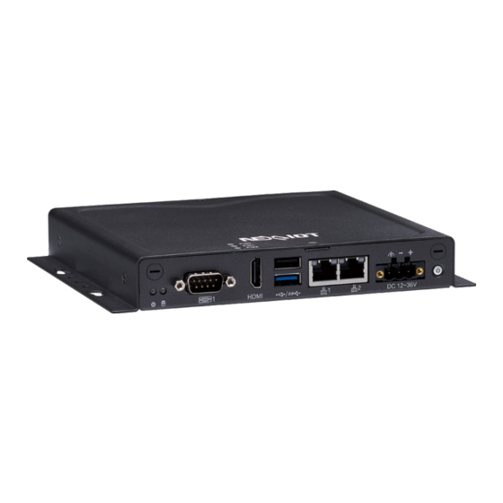
Page 18: Knowing Your Cps 50-N01
Used to connect the system to a local area network. DC Input Used to plug a DC power cord (9~30V DC, default 24V, 60W). Power Button Press to power on/off the system. SMA Antenna Hole Cover Copyright © 2023 NexAIoT Co., Ltd. All Rights Reserved. CPS 50-N01 User Manual... -
Page 19: Cps 50-N01 Mechanical Dimensions
Chapter 1: Product Introduction CPS 50-N01 Mechanical Dimensions Copyright © 2023 NexAIoT Co., Ltd. All Rights Reserved. CPS 50-N01 User Manual... -
Page 20: Chapter 2: Jumpers And Connectors
Static electricity can damage many of the electronic ▪ Use correct screws and do not over tighten screws. components. Humid environments tend to have less static electricity than Copyright © 2023 NexAIoT Co., Ltd. All Rights Reserved. CPS 50-N01 User Manual... -
Page 21: Jumper Settings
Refer to the illustrations below for examples of what the 2-pin and 3-pin jumpers look like when they are short (on) and open (off). Two-Pin Jumpers: Open (Left) and Short (Right) Three-Pin Jumpers: Pins 1 and 2 are Short Copyright © 2023 NexAIoT Co., Ltd. All Rights Reserved. CPS 50-N01 User Manual... -
Page 22: Locations Of The Jumpers And Connectors For Cps 50-N01
Chapter 2: Jumpers and Connectors Locations of the Jumpers and Connectors for CPS 50-N01 The figure below is the top view of the main board used in CPS 50-N01. It shows the locations of the jumpers and connectors. Copyright © 2023 NexAIoT Co., Ltd. All Rights Reserved. -
Page 23: Jumps
Chapter 2: Jumpers and Connectors Jumps Power Mode Select Connector type: 1x3 3-pin header Connector location: JP2 Settings 1-2 Short Normal Mode 2-3 Short Direct Power On Definition VDC_IN VSYS_5V_EN Copyright © 2023 NexAIoT Co., Ltd. All Rights Reserved. CPS 50-N01 User Manual... -
Page 24: Connector Pin Definitions
Connector location: CN5 Definition Definition Definition Definition UIO_GPIO4 HDMI_TXP2_CN UIO_GPIO3 HDMI_TXN2_CN HDMI_TXP1_CN UIO_GPIO2 HDMI_TXN1_CN UIO_GPIO1 HDMI_TXP0_CN CAN1_L_CN CAN1_H_CN HDMI_TXN0_CN HDMI_CLKP_CN HDMI_CLKN_CN HDMI_CEC_CN HDMI_Utility_CN HDMI_DDC_SCL_CN HDMI_DDC_SDA_CN HDMI_5V_CN HDMI_HPD_CN Copyright © 2023 NexAIoT Co., Ltd. All Rights Reserved. CPS 50-N01 User Manual... -
Page 25: Usb Ports
Connector type: USB 2.0 (Top) and USB 3.0 (Bottom) Type A Ports Connector location: CN6 Definition Definition USB1_VBUS_CN USB1_DN_CN USB1_DP_CN USB1_RXN_CN USB1_RXP_CN USB1_TXN_CN USB1_TXP_CN USB2_VBUS_CN USBHOST_D1_N_CN USBHOST_D1_P_CN Copyright © 2023 NexAIoT Co., Ltd. All Rights Reserved. CPS 50-N01 User Manual... -
Page 26: Dc Power Input
When connecting the power to the terminal block connector on the system, Connector location: CN12 ensure the ground pin (see the image below) on the connector is connected to a grounding stripe. Definition Power VIN Chassis GND Copyright © 2023 NexAIoT Co., Ltd. All Rights Reserved. CPS 50-N01 User Manual... -
Page 27: Lan Ports
Definition ETH1_TRX0_P ETH1_TRX0_N ETH_TRX0_P ETH_TRX0_N ETH1_TRX1_P ETH1_TRX1_N ETH_TRX1_P ETH_TRX1_N VDD_3V3 VDD_3V3 ETH1_TRX2_P ETH1_TRX2_N ETH_TRX2_P ETH_TRX2_N ETH1_TRX3_P ETH1_TRX3_N ETH_TRX3_P ETH_TRX3_N E1_10M_100M_Link/Active E1_LED1/CFGLDO0 10M_100M_Link/Active LED1/CFGLDO0 E1_1GB_Link/Active E1_LED2/CFGLDO1 1GB_Link/Active LED2/CFGLDO1 Copyright © 2023 NexAIoT Co., Ltd. All Rights Reserved. CPS 50-N01 User Manual... -
Page 28: Power Button
By default, short press to turn on or 6 seconds to turn off the system. See jumper to select the desired power mode. Definition Definition VDC_IN PWR_OFF_GPIO PWR_OFF_GPIO VDC_IN VDD_3V3 GND_Chassis GND_Chassis Copyright © 2023 NexAIoT Co., Ltd. All Rights Reserved. CPS 50-N01 User Manual... -
Page 29: Internal Connectors
Connector type: SIM card slot and 2x3 6-pin header Connector location: CN1 Connector location: CN3 Definition Definition Definition Definition VEXT_3V3 VCCP_USIM UIM_REST DSI_TP_INT DSI_TP_RST UIM_CLK DSI_TP_I2C_SCL DSI_TP_I2C_SDA UIM_VPP UIM_DATA Copyright © 2023 NexAIoT Co., Ltd. All Rights Reserved. CPS 50-N01 User Manual... -
Page 30: Mini-Pcie Slot
51 52 Definition Definition Definition Definition VCC3V3_MPCIE PCIE_TXN PCIe_nCLKREQ VCCP_USIM PCIE_TXP UIM_DATA USB_DN-MPCIE REF_CLKN_CN UIM_CLK USB_DP-MPCIE REF_CLKP_CN UIM_RESET VCC3V3_MPCIE UIM_VPP VCC3V3_MPCIE MPCIE_W_DIS MPCIE_RSTB PCIE_RXN VCC3V3_MPCIE PCIE_RXP VCC3V3_MPCIE Copyright © 2023 NexAIoT Co., Ltd. All Rights Reserved. CPS 50-N01 User Manual... -
Page 31: Board To Board Connector
USB_IO2_DN COM2_RXD COM4_RXD VCC_5V_IO UIO2_GPIO5 UIO2_GPIO6 USB3_SSTX- UIO1_GPIO2 UIO2_GPIO7 UIO2_GPIO8 USB3_SSTX+ UIO1_GPIO4 UIO2_GPIO9 UIO2_GPIO10 VCC_5V_IO UIO2_GPIO11 UIO2_GPIO12 USB_IO3_DN USB3_SSRX+ CAN1_TX I2C2_SDA USB_IO3_DP USB3_SSRX- CAN1_RX I2C2_SCL VCC_5V_IO VEXT_3V3 Copyright © 2023 NexAIoT Co., Ltd. All Rights Reserved. CPS 50-N01 User Manual... -
Page 32: Lvds Connector
LVDS1_TX0_N1 LVDS0_CLK_N1 LVDS1_CLK_P1 LVDS0_TX0_N1 LVDS1_TX0_P1 LVDS0_CLK_P1 LVDS0_TX0_P1 LVDS1_TX3_N1 LVDS1_TX1_N1 LVDS0_TX3_N1 LVDS1_TX3_P1 LVDS0_TX1_N1 LVDS1_TX1_P1 LVDS0_TX3_P1 LVDS0_TX1_P1 LVDS_LED_PWR LVDS1_TX2_N1 LVDS_VDD LVDS_LED_PWR LVDS0_TX2_N1 LVDS1_TX2_P1 LVDS_VDD LVDS_LED_PWM LVDS0_TX2_P1 LVDS_VDD LVDS_LED_EN LVDS1_CLK_N1 Copyright © 2023 NexAIoT Co., Ltd. All Rights Reserved. CPS 50-N01 User Manual... -
Page 33: Micro Sd Card Slot
Chapter 2: Jumpers and Connectors Micro SD Card Slot Connector type: Standard Micro SD Card Slot Connector location: CN10 Definition Definition SD2_DATA2 SD2_DATA3 SD2_CMD VSD_3V3 SD2_CLK SD2_DATA0 SD2_DATA1 Copyright © 2023 NexAIoT Co., Ltd. All Rights Reserved. CPS 50-N01 User Manual... -
Page 34: Connector (Key E 2330)
Definition Definition Definition CONFIG_3 VCC_3V3_IO VCC_3V3_IO POWER_OFF# USB_IO2_DP_CN W_DIS1# USB_IO2_DN_CN CONFIG_0 W_DIS2#_1V8 USB3_SSRX- USB3_SSRX+ USIM1_RESET USIM1_CLK RESET#_1V8 USIM1_DET USB3_SSTX- USIM1_DATA CONFIG_1 USB3_SSTX+ USIM1_VDD VCC_3V3_IO VCC_3V3_IO CONFIG_2 VCC_3V3_IO Copyright © 2023 NexAIoT Co., Ltd. All Rights Reserved. CPS 50-N01 User Manual... -
Page 35: Battery Connector
Battery Connector MIC Connector Connector type: 1x2 2-pin header Connector type: 1x2 2-pin header Connector location: J1 Connector location: J2 Definition Definition Definition Definition VBAT MIC0N_CON MIC0P_CON Copyright © 2023 NexAIoT Co., Ltd. All Rights Reserved. CPS 50-N01 User Manual... -
Page 36: Mipi-Dis Connector
Connector type: 1x40 40-pin header Connector location: J4 Definition Definition Definition Definition DSI_LED- DSI_LED- DSI_IOVCC(VEXT_3V3) DSI_IOVCC(VEXT_3V3) DSI_LED+ DSI_DN0 DSI_DP0 DSI_RESET DSI_DN1 DSI_DP1 DSI_VCI(VEXT_3V3) DSI_CKN DSI_VCI(VEXT_3V3) DSI_CKP DSI_DN2 DSI_DP2 DSI_DN3 DSI_DP3 Copyright © 2023 NexAIoT Co., Ltd. All Rights Reserved. CPS 50-N01 User Manual... -
Page 37: Uart2 Connector
Connector type: 1x15 15-pin header Connector location: J5 Connector location: J6 Definition Definition Definition Definition UART2_TXD CAM_D0_N UART2_RXD VDD_3V3 CAM_D0_P CAM_D1_N CAM_D0_P CAM_CK_N CAM_CK_P CAM_PWR_EN CAM_RESET CAM_SCL CAM_SDA CAM_3V3 Copyright © 2023 NexAIoT Co., Ltd. All Rights Reserved. CPS 50-N01 User Manual... -
Page 38: Lvds Touch Connector
Chapter 2: Jumpers and Connectors LVDS Touch Connector Connector type: 1x6 6-pin header Connector location: J8 Definition Definition RST_TP VDD_TP (VEXT_3V3) INT_TP USB_TP_D1_P USB_TP_D1_N Copyright © 2023 NexAIoT Co., Ltd. All Rights Reserved. CPS 50-N01 User Manual... -
Page 39: Block Diagram
Chapter 2: Jumpers and Connectors Block Diagram Copyright © 2023 NexAIoT Co., Ltd. All Rights Reserved. CPS 50-N01 User Manual... -
Page 40: Chapter 3: System Setup
1. Remove the six mounting screws around the chassis cover. There are two 2. With the screws removed, lift up the cover and remove it from the chassis. screws each on the top and on the sides. Copyright © 2023 NexAIoT Co., Ltd. All Rights Reserved. CPS 50-N01 User Manual... -
Page 41: Installing A Micro Sd Card
Pull the Micro SD card slot cover to the right ( ), lift it up ( ) to open SD cover is secured to the main board. the Micro SD cover. Micro SD Card Slot Copyright © 2023 NexAIoT Co., Ltd. All Rights Reserved. CPS 50-N01 User Manual... - Page 42 Chapter 3: System Setup Insert a Micro SD card into the Micro SD card slot. Secure the Micro SD card to the original position. Secure the Micro SD Card Copyright © 2023 NexAIoT Co., Ltd. All Rights Reserved. CPS 50-N01 User Manual...
-
Page 43: Installing A Wlan/5G/4G Lte Module (Full-Size Mini-Pcie)
Insert the module into the mini-PCIe slot at a 45-degree angle until the gold-plated connector on the edge of the module completely disappears into the slot. Mini-PCIe Socket Copyright © 2023 NexAIoT Co., Ltd. All Rights Reserved. CPS 50-N01 User Manual... - Page 44 Chapter 3: System Setup Push the module down and secure it with a mounting screw. Mounting Screw Copyright © 2023 NexAIoT Co., Ltd. All Rights Reserved. CPS 50-N01 User Manual...
-
Page 45: Installing A Wlan/ Bluetooth Mini-Pcie Module (Half-Size Mini-Pcie)
( ). Push the module down and then secure it with a mounting screw ( WLAN Module Module Bracket Mounting Hole Gold-Plated Connector Copyright © 2023 NexAIoT Co., Ltd. All Rights Reserved. CPS 50-N01 User Manual... -
Page 46: Installing A M.2 Key E Module (2230)
Insert the M.2 Key E module into the M.2 Key E slot at a 45 degrees angle until the gold-plated connector on the edge of the module completely disappears inside the slot. Mounting Hole M.2 Key E Slot Copyright © 2023 NexAIoT Co., Ltd. All Rights Reserved. CPS 50-N01 User Manual... - Page 47 Push the M.2 Key E module down and fasten an M.2 mounting screw into the mounting hole to secure the module. Secure the M.2 Key E Module Copyright © 2023 NexAIoT Co., Ltd. All Rights Reserved. CPS 50-N01 User Manual...
-
Page 48: Installing A Nano Sim Card
SIM card cover. Insert the nano SIM card into the nano SIM card slot. Nano SIM Card Slot Copyright © 2023 NexAIoT Co., Ltd. All Rights Reserved. CPS 50-N01 User Manual... - Page 49 Chapter 3: System Setup Push the nano SIM-card cover down, and pull it to the right. Secure the nano SIM card to the original position. Copyright © 2023 NexAIoT Co., Ltd. All Rights Reserved. CPS 50-N01 User Manual...
-
Page 50: Installing An Antenna
Remove the antenna cover located on the front panel/rear panel. Note: Please remove the gaskets (ring 1 and ring 2) on the SMA antenna jack first. Ring 2 Ring 1 Ring 2 Ring 1 Copyright © 2023 NexAIoT Co., Ltd. All Rights Reserved. CPS 50-N01 User Manual... - Page 51 Note: Refer to the image below for the gasket and washer hole, and insert the two rings (ring 1 and ring 2) and two washer back installation sequence. to the antenna jack. Installation Sequence Copyright © 2023 NexAIoT Co., Ltd. All Rights Reserved. CPS 50-N01 User Manual...
- Page 52 Connect the external antenna to the antenna jack. connector, one on each side as shown below. Side A Side B Side A facing inwards and each other Copyright © 2023 NexAIoT Co., Ltd. All Rights Reserved. CPS 50-N01 User Manual...
-
Page 53: Chapter 4: Software Functionality
Install the qemu-user-static on a PC to simulate arm64 environment $ sudo apt-get install qemu-user-static $ cp /usr/bin/qemu-aarch64-static usr/bin $ cp -b /etc/resolv.conf etc/ $ cd ../ Copyright © 2023 NexAIoT Co., Ltd. All Rights Reserved. CPS 50-N01 User Manual... - Page 54 # apt-get upgrade then # apt-get install apt-utils language-pack-en-base sudo ssh net-tools umnt $1 $2 network-manager iputils-ping rsyslog bash-completion htop resolvconf dialog vim udhcpc alsa-utils # unminimize Copyright © 2023 NexAIoT Co., Ltd. All Rights Reserved. CPS 50-N01 User Manual...
- Page 55 $ sudo cp -Pra ~/imx-yocto-bsp-5.4.70_2.3.3/imx8mpevk_fsl-imx- xwayland/tmp/work/imx8mpevk-poky-linux/imx-image-full/1.0-r0/ rootfs/boot/* ~/ubuntu-rootfs/boot/ $ sudo cp -Pra ~/imx-yocto-bsp-5.4.70_2.3.3/imx8mpevk_fsl-imx- xwayland/tmp/work/imx8mpevk-poky-linux/alsa-state/0.2.0-r5/image/ var/lib/alsa/asound.state ~/ubuntu-rootfs/var/lib/alsa/ $ sudo cp -Pra ~/imx-yocto-bsp-5.4.70_2.3.3/sources/meta-ec25/ recipes-ec25/ec25/ec25/quectel-CM ~/ubuntu-rootfs/usr/bin/ $ sudo cp -Pra ~/imx-yocto-bsp-5.4.70_2.3.3/sources/meta-ec25/ recipes-ec25/ec25/ec25/simcom-cm ~/ubuntu-rootfs/usr/bin/ Copyright © 2023 NexAIoT Co., Ltd. All Rights Reserved. CPS 50-N01 User Manual...
- Page 56 $ sudo chown -hR user:user ~/imx-yocto-bsp-5.4.70_2.3.3/ imx8mpevk_fsl-imx-xwayland/tmp/work/imx8mpevk-poky-linux/imx- image-full/1.0-r0/rootfs $ sudo chown root:root ~/imx-yocto-bsp-5.4.70_2.3.3/imx8mpevk_fsl- imx-xwayland/tmp/work/imx8mpevk-poky-linux/imx-image-full/1.0-r0/ rootfs/usr/lib/policykit-1/polkit-agent-helper-1 $ sudo chmod +s ~/imx-yocto-bsp-5.4.70_2.3.3/imx8mpevk_fsl-imx- xwayland/tmp/work/imx8mpevk-poky-linux/imx-image-full/1.0-r0/ rootfs/usr/lib/policykit-1/polkit-agent-helper-1 $ cd ~/imx-yocto-bsp-5.4.70_2.3.3/imx8mpevk_fsl-imx-xwayland/ $ bitbake imx-image-full -c do_image_wic -f Copyright © 2023 NexAIoT Co., Ltd. All Rights Reserved. CPS 50-N01 User Manual...
-
Page 57: Android
$ export AARCH64_GCC_CROSS_COMPILE=/opt/gcc-arm-8.3- 2019.03-x86_64-aarch64-linux-gnu/bin/aarch64-linux-gnu- $ cd ~/imx-android-10.0.0_2.6.0 $ cd android_build $ export MY_ANDROID=`pwd` $ source build/envsetup.sh $ lunch evk_8mp-userdebug $ ./imx-make.sh -j4 2>&1 | tee -a build-log.txt Copyright © 2023 NexAIoT Co., Ltd. All Rights Reserved. CPS 50-N01 User Manual... -
Page 58: Install Yocto Linux, Ubuntu, Or Android On Cps50
Connect a USB cable from a computer to the USB 3.0 port on rootfs.wic.bz2 CPS 50-N01. Change the SW1 on the mainboard of the CPS 50-N01: BOOT_MODE0 = ON (Serial Download Mode) BOOT_MODE1 = ON (boot from eMMC) BOOT_MODE0 = ON & BOOT_MODE1 = ON (boot from SD card) - Page 59 HDMI + MIPI panel display: Normal Boot Hit any key to stop autoboot: 0 u-boot=> u-boot=> setenv fdt_file imx8mp-cps50-mipi-panel-hdmi.dtb u-boot=> saveenv u-boot=> boot Copyright © 2023 NexAIoT Co., Ltd. All Rights Reserved. CPS 50-N01 User Manual...
-
Page 60: Ubuntu
Copyright © 2023 NexAIoT Co., Ltd. All Rights Reserved. CPS 50-N01 User Manual... - Page 61 HDMI + MIPI panel display: Normal Boot Hit any key to stop autoboot: 0 u-boot=> u-boot=> setenv fdt_file imx8mp-cps50-mipi-panel-hdmi.dtb u-boot=> saveenv u-boot=> boot Copyright © 2023 NexAIoT Co., Ltd. All Rights Reserved. CPS 50-N01 User Manual...
-
Page 62: Android
HDMI + LVDS + MIPI panel display: uuu_imx_android_flash.bat -f imx8mp -e HDMI + LVDS panel display: uuu_imx_android_flash.bat -f imx8mp -e -d lvds-panel HDMI + MIPI panel display: uuu_imx_android_flash.bat -f imx8mp -e -d mipi-panel Copyright © 2023 NexAIoT Co., Ltd. All Rights Reserved. CPS 50-N01 User Manual... -
Page 63: Yocto Linux Test Command On Cps50
#11 640x480 60.00 640 656 752 800 480 490 492 525 25200 flags: nhsync, nvsync; type: driver #12 640x480 59.94 640 656 752 800 480 490 492 525 25175 flags: nhsync, nvsync; type: driver Copyright © 2023 NexAIoT Co., Ltd. All Rights Reserved. CPS 50-N01 User Manual... -
Page 64: Lvds Panel Backlight
# echo 50 > /sys/class/backlight/lvds_backlight/brightness # modetest -s 42:1280x960-60 # echo 0 > /sys/class/backlight/lvds_backlight/brightness # modetest -s 42:1280x720-60 # modetest -s 42:800x600-60.32 # modetest -s 42:720x480-60 # modetest -s 42:640x480-60 Copyright © 2023 NexAIoT Co., Ltd. All Rights Reserved. CPS 50-N01 User Manual... -
Page 65: Mipi-Dsi Panel Backlight
# gst-launch-1.0 v4l2src device=/dev/video1 num-buffers=1 ! video/x- raw,width=640,height=480 ! jpegenc ! filesink location=sample.jpeg Record # gst-launch-1.0 v4l2src device=/dev/video1 num-buffers=300 ! video/x-raw,format=NV12,width=1920,height=1080,framera te=30/1 ! queue ! vpuenc_h264 ! h264parse ! mp4mux ! filesink location=sample.mp4 Copyright © 2023 NexAIoT Co., Ltd. All Rights Reserved. CPS 50-N01 User Manual... -
Page 66: Audio
# amixer -c wm8962audio cset name='INPGAR IN1R Switch' 1 # amixer -c wm8962audio cset name='INPGAL IN2L Switch' 1 # amixer -c wm8962audio cset name='Digital Playback Volume' 96 # amixer -c wm8962audio cset name='Speaker Volume' 114 Copyright © 2023 NexAIoT Co., Ltd. All Rights Reserved. CPS 50-N01 User Manual... - Page 67 # gst-play-1.0 /run/media/sda1/sample1.mp3 --audiosink="alsasink de vice=sysdefault:CARD=audiohdmi" vice=sysdefault:CARD=audiohdmi" # gst-launch-1.0 playbin uri=file:///run/media/sda1/sample1.mp3 # gst-launch-1.0 playbin uri=file:///run/media/sda1/sample1.mp3 audio-sink="alsasink device=sysdefault:CARD=wm8960audio" audio-sink="alsasink device=sysdefault:CARD=wm8962audio" # gst-launch-1.0 playbin uri=file:///run/media/sda1/sample1.mp3 # gst-launch-1.0 playbin uri=file:///run/media/sda1/sample1.mp3 audio-sink="alsasink device=sysdefault:CARD=audiohdmi" audio-sink="alsasink device=sysdefault:CARD=audiohdmi" Copyright © 2023 NexAIoT Co., Ltd. All Rights Reserved. CPS 50-N01 User Manual...
-
Page 68: Wi-Fi
# hciconfig -a # bluetoothctl [bluetooth]# discoverable on [bluetooth]# pairable on [bluetooth]# scan on [NEW] Device 28:7F:CF:F3:EA:52 28-7F-CF-F3-EA-52 [bluetooth]# scan off [bluetooth]# pair 28:7F:CF:F3:EA:52 [bluetooth]# connect 28:7F:CF:F3:EA:52 Copyright © 2023 NexAIoT Co., Ltd. All Rights Reserved. CPS 50-N01 User Manual... -
Page 69: Ethernet
UP LOOPBACK RUNNING MTU:65536 Metric:1 RX packets:3566 errors:0 dropped:0 overruns:0 frame:0 TX packets:3566 errors:0 dropped:0 overruns:0 carrier:0 collisions:0 txqueuelen:1000 RX bytes:218960 (213.8 KiB) TX bytes:218960 (213.8 KiB) Copyright © 2023 NexAIoT Co., Ltd. All Rights Reserved. CPS 50-N01 User Manual... -
Page 70: 4G Lte
# quectel-CM -i wwan0 -p 0000 & # ifconfig can0 up # ifconfig wwan0 up # candump can0 & # udhcpc -i wwan0 # cansend can0 1F334455#1122334455667788 Copyright © 2023 NexAIoT Co., Ltd. All Rights Reserved. CPS 50-N01 User Manual... -
Page 71: Led
NEXCOM IO board (CPSK-501) CAN bus LED: # echo netdev > /sys/class/leds/can0_led/trigger # echo can0 > /sys/class/leds/can0_led/device_name # echo 1 > /sys/class/leds/can0_led/link # echo 1 > /sys/class/leds/can0_led/tx # echo 1 > /sys/class/leds/can0_led/rx Copyright © 2023 NexAIoT Co., Ltd. All Rights Reserved. CPS 50-N01 User Manual... - Page 72 # echo "Serial Port Test" > /dev/ttymxc0 Set Direction Transmit: # echo 149 > /sys/class/gpio/export # echo out > /sys/class/gpio/gpio149/direction # echo 1 > /sys/class/gpio/gpio149/value # echo "Serial Port Test" > /dev/ttymxc0 Copyright © 2023 NexAIoT Co., Ltd. All Rights Reserved. CPS 50-N01 User Manual...
- Page 73 # stty -F /dev/ttyUSB0 speed 115200 ignbrk -brkint -icrnl -imaxbel # echo test > /dev/ttymxc1 -opost -onlcr -isig -icanon -iexten -echo -echoe -echok -echoctl -echoke # cat /dev/ttyUSB0 & # echo "Serial Port Test" > /dev/ttyUSB0 Copyright © 2023 NexAIoT Co., Ltd. All Rights Reserved. CPS 50-N01 User Manual...
- Page 74 # cat /dev/ttymxc1 & Set Direction Transmit: # echo 141 > /sys/class/gpio/export # echo out > /sys/class/gpio/gpio141/direction # echo 1 > /sys/class/gpio/gpio141/value # echo "Serial Port Test" > /dev/ttymxc1 Copyright © 2023 NexAIoT Co., Ltd. All Rights Reserved. CPS 50-N01 User Manual...
- Page 75 # cat /dev/ttymxc3 & Set Direction Transmit: # echo 140 > /sys/class/gpio/export # echo out > /sys/class/gpio/gpio140/direction # echo 1 > /sys/class/gpio/gpio140/value # echo "Serial Port Test" > /dev/ttymxc3 Copyright © 2023 NexAIoT Co., Ltd. All Rights Reserved. CPS 50-N01 User Manual...
-
Page 76: Uio-4030: 4 Di & 4 Do
UIO2_GPIO5 in: # echo 499 > /sys/class/gpio/export # echo in > /sys/class/gpio/gpio499/direction # echo 503 > /sys/class/gpio/export # cat /sys/class/gpio/gpio499/value # echo in > /sys/class/gpio/gpio503/direction # cat /sys/class/gpio/gpio503/value Copyright © 2023 NexAIoT Co., Ltd. All Rights Reserved. CPS 50-N01 User Manual... - Page 77 UIO2_GPIO5 in: # echo 499 > /sys/class/gpio/export # echo 503 > /sys/class/gpio/export # echo in > /sys/class/gpio/gpio499/direction # echo in > /sys/class/gpio/gpio503/direction # cat /sys/class/gpio/gpio499/value # cat /sys/class/gpio/gpio503/value Copyright © 2023 NexAIoT Co., Ltd. All Rights Reserved. CPS 50-N01 User Manual...
-
Page 78: Nexcom Io Board (Cpsk-501) Uio_Gpio
# echo 499 > /sys/class/gpio/export # echo 499 > /sys/class/gpio/export # echo out > /sys/class/gpio/gpio499/direction # echo in > /sys/class/gpio/gpio499/direction # echo 1 > /sys/class/gpio/gpio499/value # cat /sys/class/gpio/gpio499/value Copyright © 2023 NexAIoT Co., Ltd. All Rights Reserved. CPS 50-N01 User Manual... -
Page 79: Rtc
Sat Jan 1 00:00:00 UTC 2000 09:00:43 +0000) Restore the RTC time to system time: # hwclock -s && date Sat Oct 23 08:26:33 UTC 2021 RTC test: # /unit_tests/SRTC/rtctest.out Copyright © 2023 NexAIoT Co., Ltd. All Rights Reserved. CPS 50-N01 User Manual... -
Page 80: Usb Storage Copy File
Chapter 4: Software Functionality USB storage copy file MicroSD card copy file # rsync -av --progress /run/media/sda1/file1 /run/media/sda1/file2 # rsync -av --progress /run/media/mmcblk1p1/file1 /run/media/ mmcblk1p1/file2 Copyright © 2023 NexAIoT Co., Ltd. All Rights Reserved. CPS 50-N01 User Manual... -
Page 81: I2C Reset Pmic Pca9450
Chapter 4: Software Functionality i2c reset PMIC pca9450 Thermal CPU & SoC temperature # echo 06 14 > /sys/devices/platform/soc@0/30800000.bus/30a20000. # cat /sys/class/thermal/thermal_zone0/temp i2c/i2c-0/0-0025/pca9450-pmic/registers # cat /sys/class/thermal/thermal_zone1/temp Copyright © 2023 NexAIoT Co., Ltd. All Rights Reserved. CPS 50-N01 User Manual... -
Page 82: Thermal Cpu & Soc Passive & Critical Temperature Setting
# echo 85000 > /sys/class/thermal/thermal_zone1/trip_point_0_temp # echo 95000 > /sys/class/thermal/thermal_zone1/trip_point_1_temp Industrial: # echo 95000 > /sys/class/thermal/thermal_zone0/trip_point_0_temp # echo 105000 > /sys/class/thermal/thermal_zone0/trip_point_1_temp # echo 95000 > /sys/class/thermal/thermal_zone1/trip_point_0_temp # echo 105000 > /sys/class/thermal/thermal_zone1/trip_point_1_temp Copyright © 2023 NexAIoT Co., Ltd. All Rights Reserved. CPS 50-N01 User Manual... -
Page 83: Cpu Frequency & Cpu & Soc Temperature
CPU Frequency & CPU & SoC temperature ATECC608A # cpuFreqTemp.sh & # atecc -b 1 -s 192 -c serial # cat /home/root/cpu_freq_temp.log 0123952aef4c6321ee # atecc -b 1 -s 192 -c info Found ATECC608A Copyright © 2023 NexAIoT Co., Ltd. All Rights Reserved. CPS 50-N01 User Manual... -
Page 84: Appendix A: System Recovery
▪ Recovery Image (For more detailed info, please contact NEXAIoT). ▪ A 64-bit Linux host O/S on a PC (Virtual Machines are not recommended) ▪ USB cable to connect the host PC to the CPS 50-N01. CPU Heatsink Copyright © 2023 NexAIoT Co., Ltd. All Rights Reserved. - Page 85 Connect the DC 12 or 24V cable to the CPS 50-N01 and it will trigger the serial download mode to restore the image from the host PC. After the restore process has completed, it will show on the host PC...
- Page 86 Appendix A: GPI/O Programming Guide Remove the DC 12 or 24V cable on the CPS 50-N01, and set the SW1 switch setting back to Normal mode (SW1: PIN1 to ON, PIN2 to OFF). Put back the CPU heatsink, and fasten two screws.
Need help?
Do you have a question about the CPS 50-N01 and is the answer not in the manual?
Questions and answers