
Related Manuals for NexAIoT NISE 109


Summary of Contents for NexAIoT NISE 109
- Page 1 NexAIoT Co., Ltd. IoT Automation Solutions Business Group Fan-less Computer NISE 109 User Manual NexAIoT Co., Ltd. www.nexaiot.com Published January 2022...
-
Page 2: Table Of Contents
Knowing Your NISE 109 ................4 SATA Connector ................15 Front Panel ..................4 GPIO Connector ................15 Rear Panel ...................5 COM1 Connector ................16 Mechanical Dimensions ................6 COM2 Connector ................16 COM3 Connector ................17 Copyright © 2021 NexAIoT Co., Ltd. All Rights Reserved. NISE 109 User Manual... - Page 3 LVDS Connector 2 of 2 (Reserved for APPC/IPPC project) ....27 Main ....................47 Advanced ..................48 Chipset ....................56 Security .....................57 Boot ....................58 Save & Exit ..................59 Appendix A: LED Status .........60 Copyright © 2021 NexAIoT Co., Ltd. All Rights Reserved. NISE 109 User Manual...
-
Page 4: Preface
Acknowledgements The product(s) described in this manual complies with all applicable NISE 109 is a trademark of NexAIoT Co., Ltd. All other product names European Union (CE) directives if it has a CE marking. For computer systems mentioned herein are registered trademarks of their respective owners. -
Page 5: Rohs Compliance
(Cr6+) < 0.1% or 1,000ppm, Polybrominated biphenyls (PBB) < 0.1% or 1,000ppm, and Polybrominated diphenyl Ethers (PBDE) < 0.1% or 1,000ppm. In order to meet the RoHS compliant directives, NexAIoT has established an engineering and manufacturing task force to implement the introduction of green products. -
Page 6: Warranty And Rma
“NexAIoT RMA Service Form” for the RMA number apply process. ▪ If RMA goods can not be repaired, NexAIoT will return it to the customer without any charge. ▪ Customers can send back the faulty products with or without accessories (manuals, cable, etc.) and any components from the card, such as CPU... -
Page 7: Installation Recommendations
Using your fingers can disconnect most of the connections. It is recommended that you do not use needle-nose pliers to disconnect connections as these can damage the soft metal or plastic parts of the connectors. Copyright © 2021 NexAIoT Co., Ltd. All Rights Reserved. NISE 109 User Manual... -
Page 8: Safety Information
Discard used batteries according to the manufacturer’s instructions. ▪ This product is intended to be supplied by an approved power adapter, rated 12Vdc, 5A or 24Vdc, 2.5A minimum and Tma 55 degree Celsius. If further assistance is needed, please contact NexAIoT for further information. viii Copyright ©... -
Page 9: Safety Precautions
ACCORDING TO THE MANUFACTURER’S INSTRUCTIONS. 11. If the equipment is not used for a long time, disconnect it from the power source to avoid damage by transient overvoltage. Copyright © 2021 NexAIoT Co., Ltd. All Rights Reserved. NISE 109 User Manual... -
Page 10: Technical Support And Assistance
Preface Technical Support and Assistance Conventions Used in this Manual 1. For the most updated information of NexAIoT products, visit NexAIoT’s Warning: website at www.nexaiot.com. Information about certain situations, which if not observed, can cause personal injury. This will prevent injury to yourself 2. -
Page 11: Global Service Contact Information
Fax: +886-2-8226-7782 Shanghai, 201108, China Taichung City, 406, Taiwan, R.O.C. Email: sales@nexcom.com.tw Tel: +86-21-5278-5868 Tel: +886-4-2249-1179 www.nexcom.com.tw Fax: +86-21-3251-6358 Fax: +886-4-2249-1172 Email: sales@nexaiot.com Email: sales@nexcom.cn www.nexaiot.com www.nexcom.cn Copyright © 2021 NexAIoT Co., Ltd. All Rights Reserved. NISE 109 User Manual... - Page 12 9F, Tamachi Hara Bldg., Chongqing City, 402160, China 4-11-5, Shiba Minato-ku, Tel: +86-23-4960-9080 Tokyo, 108-0014, Japan Fax: +86-23-4966-5855 Tel: +81-3-5419-7830 Email: sales@nexgol.com.cn Fax: +81-3-5419-7832 www.nexcobot.com/NexGOL Email: sales@nexcom-jp.com www.nexcom-jp.com Copyright © 2021 NexAIoT Co., Ltd. All Rights Reserved. NISE 109 User Manual...
-
Page 13: Package Contents
Preface Package Contents Before continuing, verify that the package that you received is complete. Your NISE 109 package should have all the items listed in the following table. Item Part Number Description 4NCPM00302X00 (T)Terminal Blocks 3P Phoenix Contact:1777992 5.08mm MALE DIP GREEN 4NCPM00203X00 Terminal Blocks 2P Phoenix Contact:1803578 3.81mm MALE ASSY GREEN... -
Page 14: Ordering Information
® ® ▪ 24V, 60W AC to DC power adapter w/o power cord (P/N: 7400060054X00) ▪ 24V, 120W AC /DC power adapter w/o power cord (P/N: 7400120029X00) Copyright © 2021 NexAIoT Co., Ltd. All Rights Reserved. NISE 109 User Manual... -
Page 15: Chapter 1: Product Introduction
▪ Operation temperature - Intel Celeron J6412: -5~55°C ® ® x6211E: -20~70°C - Intel Atom ® ▪ Support 1 x M.2 & 1 x mini-PCIe expansion slot Copyright © 2021 NexAIoT Co., Ltd. All Rights Reserved. NISE 109 User Manual... -
Page 16: Hardware Specifications
▪ 1 x Optional I/F window ▪ 3-pin DC input, support 9~30V DC Dimensions ▪ 185mm (W) x 131mm (D) x 54mm (H) without wall mount bracket Copyright © 2021 NexAIoT Co., Ltd. All Rights Reserved. NISE 109 User Manual... - Page 17 Environment ▪ Operating temperature (according to IEC60068-2-1, IEC60068-2-2, IEC60068-2-14): – NISE 109-E01 ambient with air flow: -20°C to 70°C – NISE 109-E02 ambient with air flow: -5°C to 55°C ▪ Storage temperature: -20°C to 80°C ▪ Relative humidity: 10% to 90% (non-condensing) ▪...
-
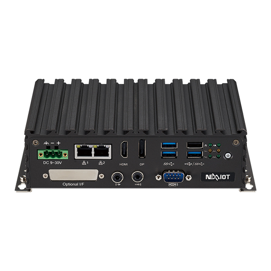
Page 18: Knowing Your Nise 109
Used to plug a DC power cord. – COM1: RS232/422/485 with auto flow control Mic-In/Line-Out Mic-In: Used to connect an external microphone Line-Out: Used to connect a headphone or a speaker. Copyright © 2021 NexAIoT Co., Ltd. All Rights Reserved. NISE 109 User Manual... -
Page 19: Rear Panel
USB 2.0 ports to connect the system with USB 2.0/1.1 devices. – COM2: RS232/422/485 with auto flow control – COM3&4: RS232 2-pin remote USB2.0 power on/off switch COM2: RS232/422/485 COM3&4: RS232 Copyright © 2021 NexAIoT Co., Ltd. All Rights Reserved. NISE 109 User Manual... -
Page 20: Mechanical Dimensions
Chapter 1: Product Introduction Mechanical Dimensions 184.85 Copyright © 2021 NexAIoT Co., Ltd. All Rights Reserved. NISE 109 User Manual... -
Page 21: Chapter 2: Jumpers And Connectors
Static electricity can damage many of the electronic ▪ Use correct screws and do not over tighten screws. components. Humid environments tend to have less static electricity than Copyright © 2021 NexAIoT Co., Ltd. All Rights Reserved. NISE 109 User Manual... -
Page 22: Jumper Settings
Refer to the illustrations below for examples of what the 2-pin and 3-pin jumpers look like when they are short (on) and open (off). Two-Pin Jumpers: Open (Left) and Short (Right) Three-Pin Jumpers: Pins 1 and 2 are Short Copyright © 2021 NexAIoT Co., Ltd. All Rights Reserved. NISE 109 User Manual... -
Page 23: Locations Of The Jumpers And Connectors For Nisb 109
Locations of the Jumpers and Connectors for NISB 109 NISB 109 The figure below is the top view of the NISB 109 main board which is the main board used in NISE 109. It shows the locations of the jumpers and connectors. Top View... -
Page 24: Bottom View
Chapter 2: Jumpers and Connectors JFW1 BAT1 SIM1 DIMM1 Bottom View OUT1 MIC1 COM3 COM4 COM1 COM2 Copyright © 2021 NexAIoT Co., Ltd. All Rights Reserved. NISE 109 User Manual... -
Page 25: Dip Switches
MODE Status AT (PWR BT available) Clease CMOS AT (PWR BT invalid) Normal (Default) Definition Definition I_RTCRSTL PBT_PU I_RTCTESTL PBT_PU ATX_PBT AT_PWRBT# Default: 1-OFF, 2-OFF, 3-OFF, 4-OFF Copyright © 2021 NexAIoT Co., Ltd. All Rights Reserved. NISE 109 User Manual... -
Page 26: Connector Pin Definitions
Definition Definition Definition 5VSBUSB2 IUSB2N0 5VSBUSB3 IUSB2N5 IUSB2P0 IUSB2P5 5VSBUSB2 IUSB2N3 IUSB3CRXN0 IUSB3CRXP0 IUSB2P3 IUSB3CTXN0 NEAR_GND NEAR_GND IUSB3CTXP0 5VSBUSB3 NEAR_GND NEAR_GND 1USB2N1 1USB2P1 CHASIS_GND CHASIS_GND CHASIS_GND CHASIS_GND Copyright © 2021 NexAIoT Co., Ltd. All Rights Reserved. NISE 109 User Manual... -
Page 27: Usb3.0 Ports X2
HDMITX1N1 IUSB3CRXN1 IUSB3CRXP1 HDMITX0P1 IUSB3CTXN1 HDMITX0N1 HDMICLKP1 IUSB3CTXP1 5VSBUSB1 HDMICLKN1 IUSB2N4 IUSB2P4 IUSB3CRXN2 HDMIDDCSCL HDMIDDCSDA IUSB3CRXP2 VCC5HDMI IUSB3CTXN2 IUSB3CTXP2 HDMIHPD CHASIS_GND CHASIS_GND CHASIS_GND CHASIS_GND CHASIS_GND HDMIMH2 CHASIS_GND Copyright © 2021 NexAIoT Co., Ltd. All Rights Reserved. NISE 109 User Manual... -
Page 28: Displayport Connector
CONFIG1 CONFIG2 LAN1LEDACTL LAN1LEDPWR AUX_P CHASIS_GND AUX_N DPHPD LAN2MDI0P LAN2MDI0N RETURN 3V3DPPWR LAN2MDI1P LAN2MDI1N LAN2TVCC1 CHASIS_GND CHASIS_GND LAN2MDI2P LAN2MDI2N CHASIS_GND LAN2MDI3P LAN2MDI3N LAN2LINK1000L LAN2LINK100L1 LAN2LEDACTL LAN2LEDPWR CHASIS_GND Copyright © 2021 NexAIoT Co., Ltd. All Rights Reserved. NISE 109 User Manual... -
Page 29: Internal Connectors
Connector type: Standard Serial ATAII 7P (1.27mm, SATA-M-180) Connector location: CN4 Definition Definition Definition Definition SATATXP0 GPIO_PWR SATATXN0 GPO0_OUT GPI0_IN SATARXN0 SATARXP0 GPO1_OUT GPI1_IN GPO2_OUT GPI2_IN GPO3_OUT GPI3_IN Copyright © 2021 NexAIoT Co., Ltd. All Rights Reserved. NISE 109 User Manual... -
Page 30: Com1 Connector
Connector type: 1x10, 10-pin header Connector location: COM1 Connector location: COM2 Definition Definition Definition Definition COM1DCDL COM1RXD COM2DCDL COM2RXD COM1TXD COM1DTRL COM2TXD COM2DTRL COM1DSRL COM2DSRL COM1RTSL COM1CTSL COM2RTSL COM2CTSL COM1RIL COM2RIL_CON Copyright © 2021 NexAIoT Co., Ltd. All Rights Reserved. NISE 109 User Manual... -
Page 31: Com3 Connector
Connector type: 1x10, 10-pin header Connector location: COM3 Connector location: COM4 Definition Definition Definition Definition COM3DCDL COM3RXD COM4DCDL COM4RXD COM3TXD COM3DTRL COM4TXD COM4DTRL COM3DSRL COM4DSRL COM3RTSL COM3CTSL COM4RTSL COM4CTSL COM3RIL COM4RIL Copyright © 2021 NexAIoT Co., Ltd. All Rights Reserved. NISE 109 User Manual... -
Page 32: De1 Connector
Connector location: SW1 Connector type: 1x10, 10-pin header Connector location: DE1 Definition Definition Definition Definition I_PLTRSTL ATX_PBT I_ESPICLK I_ESPICS0L ATX_PBT I_ESPIIO3 I_ESPIIO2 PWRLED_N N16937976 I_ESPIIO1 I_ESPIIO0 I_ESPIRSTL 3VSB Copyright © 2021 NexAIoT Co., Ltd. All Rights Reserved. NISE 109 User Manual... -
Page 33: Audio Line In Connector
Audio Line Out Connector Connector type: 1x4, 4-pin header Connector type: 1x4, 4-pin header Connector location: OUT1 Connector location: IN1 Definition Definition LINE1-L1 LINE_OUT_LC AGND AGND LINEIN_JD LINEOUT_JD LINE1-R1 LINE_OUT_RC Copyright © 2021 NexAIoT Co., Ltd. All Rights Reserved. NISE 109 User Manual... -
Page 34: Audio Mic In Connector
Vin Power Terminal Block Connector type: 1x4, 4-pin header Connector type: 1x3, 3-pin header Connector location: MIC1 Connector location: J1 Definition Definition Definition MIC_OUT-L VINP1 VINVSS AGND VINPGND MIC_JD MIC_OUT-R Copyright © 2021 NexAIoT Co., Ltd. All Rights Reserved. NISE 109 User Manual... -
Page 35: Lcd Backlight Connector
SATA Power Connector Connector type: 1x7, 7-pin header Connector type: 1x2, 2-pin header Connector location: J2 Connector location: J3 Definition Definition Definition VCC5 V_INV SATAPWR V_INV 3V5VEDPBKLCTL BUFEDPBKLEN Copyright © 2021 NexAIoT Co., Ltd. All Rights Reserved. NISE 109 User Manual... -
Page 36: Flash Bios Pin Header
Remote Power On/Off THR Connector type: 2x3, 6-pin header Connector type: 1x2, 2-pin header Connector location: JFW1 Connector location: JP1 Definition Definition Definition VSPI BIOSSPICSL0 BIOSSPICLK PWRBTN#_J BIOSSPISO BIOSSPISI Copyright © 2021 NexAIoT Co., Ltd. All Rights Reserved. NISE 109 User Manual... -
Page 37: Panel Led Pin Header
Panel LED Pin Header Reset Pin Header Connector type: 1x3, 3-pin header Connector type: 1x2, 2-pin header Connector location: JP2 Connector location: JP3 Definition Definition N17473943 SYSRESETN N17472512 Copyright © 2021 NexAIoT Co., Ltd. All Rights Reserved. NISE 109 User Manual... -
Page 38: Lcd Backlight Control Voltage Select Pin Header
LCD Voltage Select Pin Header Connector type: 1x3, 3-pin header Connector type: 1x3, 3-pin header Connector location: JP4 Connector location: JP5 Definition Definition VCC5 VCC5 3V5BKLPWR 3V5VLCDPWR VCC3 VCC3 Copyright © 2021 NexAIoT Co., Ltd. All Rights Reserved. NISE 109 User Manual... -
Page 39: Usb2.0 Port Pin Header
Connector type: 1x3, 3-pin header Connector type: 2x4, 8-pin header Connector location: JP7 Connector location: JP6 Definition Definition Definition INTUSB2PWR COM2RIL USB2N6 USB2P9 COM2RIL_CON USB2P6 USB2N9 VCC5 INTUSB2PWR Copyright © 2021 NexAIoT Co., Ltd. All Rights Reserved. NISE 109 User Manual... -
Page 40: Remote Power On/Off & S3 Pin Header
Remote Power On/Off & S3 Pin Header Nano SIM Connector Connector type: 1x3, 3-pin header Connector location: SIM1 Connector location: JP8 Definition Definition Definition SLP_S3#_J UIM_PWR UIM_RESET UIM_SIM_CLK PWRBTN#_J UIM_VPP UIM_DATA Copyright © 2021 NexAIoT Co., Ltd. All Rights Reserved. NISE 109 User Manual... -
Page 41: Lvds Connector 1 Of 2 (Reserved For Appc/Ippc Project)
CH_LVDSTP0 VCC_LCD CH_LVDSTP4 CH_LVDSTP3 CH_LVDSTN0 CH_LVDSTP7 CH_LVDSTN4 CH_LVDSTN3 VCC_LCD CH_LVDSTN7 VCC_LCD CH_LVDSTP1 CH_LVDSTP5 CH_LVDSCLKP1 CH_LVDSTN1 CH_LVDSCLKP2 CH_LVDSTN5 CH_LVDSCLKN1 CH_LVDSCLKN2 V_INV V_INV CH_LVDSTP2 V_INV CH_LVDSTP6 V_INV CH_LVDSTN2 CH_LVDSTN6 Copyright © 2021 NexAIoT Co., Ltd. All Rights Reserved. NISE 109 User Manual... -
Page 42: Rtc Battery
Chapter 2: Jumpers and Connectors RTC Battery Connector location: BAT1 Definition 3V_BAT1 Copyright © 2021 NexAIoT Co., Ltd. All Rights Reserved. NISE 109 User Manual... -
Page 43: M.2 Key B Connector
LTEPERSTL S_GP42 M2REFCLKN I_USB2P7 S_GP43 LTEPEWAKE1 M2REFCLKP I_USB2N7 M2REFCLK M2BCONFIG0 LTEPEWAKE2 M2LTERSTL M2B_SUSCLK M2BCONFIG1 UIM_VPP USB3RXN3 M2LTEPWR UIM_RESET USB3RXP3 M2LTEPWR UIM_CLK M2LTEPWR M2BCONFIG2 UIM_DATA USB3TXN3 UIM_PWR USB3TXP3 Copyright © 2021 NexAIoT Co., Ltd. All Rights Reserved. NISE 109 User Manual... -
Page 44: Mini Pcie Connector
Definition I_WAKEL 3VSB_MINILTE I_USB2N8 1V5_MINI I_USB2P8 I_PCIECLKREQL5 UIM_PWR UIM_DATA I_PCIECLKOUTN5 UIM_CLK I_PCIECLKOUTP5 UIM_RESET LTEPERSTL UIM_VPP 1V5_MINI LTEPEWAKE1 LTEDISL 3VSB_MINILTE LTERSTL I_PCIERXN4 3VSB_MINILTE I_PCIERXP4 1V5_MINI I_SMB3P3CLK I_PCIETXN4 I_SMB3P3DATA Copyright © 2021 NexAIoT Co., Ltd. All Rights Reserved. NISE 109 User Manual... -
Page 45: Chapter 3: System Setup
CAUTION! power is off and disconnected from the power sources to prevent electric shock or system damage. 1. Remove the six mounting screws from the bottom cover. Copyright © 2021 NexAIoT Co., Ltd. All Rights Reserved. NISE 109 User Manual... -
Page 46: Installing A So-Dimm Memory Module
The ejector tabs at the ends of the socket will automatically snap into the locked position to hold the module in place. Note: Remove the bottom cover before installing a SO-DIMM. 1. Locate the SO-DIMM socket. Memory Module SO-DIMM Socket Copyright © 2021 NexAIoT Co., Ltd. All Rights Reserved. NISE 109 User Manual... - Page 47 Chapter 3: System Setup 3. Push the module down until the clips on both sides of the socket lock into position. Memory Module Copyright © 2021 NexAIoT Co., Ltd. All Rights Reserved. NISE 109 User Manual...
-
Page 48: Installing A Sim Card
Chapter 3: System Setup Installing a SIM Card 1. Locate the SIM card holder on the board. 2. Follow steps to release SIM holder cover. SIM holder Copyright © 2021 NexAIoT Co., Ltd. All Rights Reserved. NISE 109 User Manual... - Page 49 Chapter 3: System Setup 3. Insert your SIM card. 4. Follow the steps to lock the SIM holder. Copyright © 2021 NexAIoT Co., Ltd. All Rights Reserved. NISE 109 User Manual...
-
Page 50: Installing A Mini-Pcie Module
Installing a Mini-PCIe Module 1. Locate the mini-PCIe slot on the board. 2. Install the mini-PCIe bracket to the mini-PCIe module. (When using a half-size module) Mini-PCIe socket Screw Copyright © 2021 NexAIoT Co., Ltd. All Rights Reserved. NISE 109 User Manual... - Page 51 4. Push the module down and secure it with a screw. until the gold-plated connector on the edge of the module completely disappears into the slot. Mini-PCIe module Copyright © 2021 NexAIoT Co., Ltd. All Rights Reserved. NISE 109 User Manual...
-
Page 52: Installing An M.2 Module (2242)
2. Make sure the gold-plated six-pin connector on the edge of the module is on the left, while the five-pin connector is on the right. M.2 B-key slot Five-pin Six-pin Copyright © 2021 NexAIoT Co., Ltd. All Rights Reserved. NISE 109 User Manual... - Page 53 4. Push the module down and secure it with a screw. gold-plated connector on the edge of the module completely disappears into the slot. M.2 B-key module Copyright © 2021 NexAIoT Co., Ltd. All Rights Reserved. NISE 109 User Manual...
-
Page 54: Wall Mounting Instructions
Fasten screws to mount the system to the wall Note: Specification of the wall mount screw: Round Head Screw Long Fei: P6#32Tx 1/ 4/ SW7*0.8 w/ Spring+Flat Washer Copyright © 2021 NexAIoT Co., Ltd. All Rights Reserved. NISE 109 User Manual... -
Page 55: Chapter 4: Bios Setup
This chapter describes how to use the BIOS setup program for NISE 109. The The settings made in the setup program affect how the computer performs. BIOS screens provided in this chapter are for reference only and may change It is important, therefore, first to try to understand all the setup options, and if the BIOS is updated in the future. -
Page 56: Default Configuration
Powering on the computer and immediately pressing allows you to enter Setup. Load optimized default values. Saves and exits the Setup program. Press <Enter> to enter the highlighted sub-menu. Copyright © 2021 NexAIoT Co., Ltd. All Rights Reserved. NISE 109 User Manual... - Page 57 When “” appears on the left of a particular field, it indicates that a submenu which contains additional options are available for that field. To display the submenu, move the highlight to that field and press Copyright © 2021 NexAIoT Co., Ltd. All Rights Reserved. NISE 109 User Manual...
-
Page 58: Bios Setup Utility
Stepping System Date [Thu 01/06/2022] Number of Processors 4Core(s)/ 4Thread(s) System Time [13:48:54] ▼ ▼ Version 2.21.1278. Copyright (C) 2021 AMI Version 2.21.1278. Copyright (C) 2021 AMI Copyright © 2021 NexAIoT Co., Ltd. All Rights Reserved. NISE 109 User Manual... -
Page 59: Advanced
F1: General Help hardware capabilities provided by Vanderpool Technology. F2: Previous Values F3: Optimized Defaults F4: Save & Exit ESC: Exit Version 2.21.1278. Copyright (C) 2021 AMI Copyright © 2021 NexAIoT Co., Ltd. All Rights Reserved. NISE 109 User Manual... - Page 60 Allows more than two frequency ranges to be supported. C states Enable/Disable CPU Power Management. Allows CPU to go to C states when it's not 100% utilized. Copyright © 2021 NexAIoT Co., Ltd. All Rights Reserved. NISE 109 User Manual...
- Page 61 Security Device. TCG EFI protocol and INT1A interface will not be available. SHA-1 PCR Bank Enables or disables SHA-1 PCR Bank. SHA256 PCR Bank Enables or disables SHA256 PCR Bank. Copyright © 2021 NexAIoT Co., Ltd. All Rights Reserved. NISE 109 User Manual...
- Page 62 Configuration settings for serial port 1 to port 4. Select this to change the serial port mode to RS232, RS422, RS485 w/o Terminator, or RS485 W/ Terminator. Terminal resistor Enable or disable terminal resistor. Copyright © 2021 NexAIoT Co., Ltd. All Rights Reserved. NISE 109 User Manual...
- Page 63 Select this to change the serial port mode to RS232, RS422, RS485 w/o Terminator, or RS485 W/ Terminator. Terminator, or RS485 W/ Terminator. Terminal resistor Terminal resistor Enable or disable terminal resistor. Enable or disable terminal resistor. Copyright © 2021 NexAIoT Co., Ltd. All Rights Reserved. NISE 109 User Manual...
- Page 64 Terminator, or RS485 W/ Terminator. Detects and displays the current system temperature. Terminal resistor VCC5 to VCORE Enable or disable terminal resistor. Detects and displays the output voltages. Copyright © 2021 NexAIoT Co., Ltd. All Rights Reserved. NISE 109 User Manual...
- Page 65 XHCI ownership change should be claimed by the XHCI driver. USB Transfer Time-out The time-out value for control, bulk, and Interrupt transfers. Device reset time-out Selects the USB mass storage device’s start unit command timeout. Copyright © 2021 NexAIoT Co., Ltd. All Rights Reserved. NISE 109 User Manual...
- Page 66 F4: Save & Exit ESC: Exit ESC: Exit Version 2.21.1278. Copyright (C) 2021 AMI Version 2.21.1278. Copyright (C) 2021 AMI Network Stack Enables or disables UEFI network stack. Copyright © 2021 NexAIoT Co., Ltd. All Rights Reserved. NISE 109 User Manual...
-
Page 67: Chipset
(G3 state). PCH-IO Configuration Enters the PCH-IO Configuration submenu. USB Power State in S5 Configures the USB power state in S5 for USB (CN3, CN1, USB1, JP6). Copyright © 2021 NexAIoT Co., Ltd. All Rights Reserved. NISE 109 User Manual... -
Page 68: Security
Control detection of the HD audio device. Select this to reconfigure the administrator’s password. Disabled HD audio will be unconditionally disabled. Enabled HD audio will be unconditionally enabled. Copyright © 2021 NexAIoT Co., Ltd. All Rights Reserved. NISE 109 User Manual... -
Page 69: Boot
Adjust the boot sequence of the system. Boot Option #1 is the first boot device that the system will boot from, next will be #2 and so forth. Copyright © 2021 NexAIoT Co., Ltd. All Rights Reserved. NISE 109 User Manual... -
Page 70: Save & Exit
To exit the Setup utility and reset without saving the changes, select this field then press <Enter>. You may be prompted to confirm again before exiting. You can also press <ESC> to exit without saving the changes. Copyright © 2021 NexAIoT Co., Ltd. All Rights Reserved. NISE 109 User Manual... -
Page 71: Appendix A: Led Status
A: Storage (for HDD, SSD, M.2), light up when lower than 2.3V, Green B: Battery, light up when lower than 2.3V, Green C/D: TX/RX for COM1, Yellow E/F: TX/RX for COM2, Green Copyright © 2021 NexAIoT Co., Ltd. All Rights Reserved. NISE 109 User Manual...
Need help?
Do you have a question about the NISE 109 and is the answer not in the manual?
Questions and answers