
Related Manuals for hager TYFS671D


Summary of Contents for hager TYFS671D
- Page 1 Operating and assembly instructions KNX Building system technology DALI Gateway KNX DALI 2 Gateway, Secure, 1-cannel/ 2-channel TYFS671D/ TYFS672D...
-
Page 3: Table Of Contents
DALI Gateway 1 channel, DALI Gateway 2 channels Table of contents Safety instructions ...................... 3 Function .......................... 3 Operation .......................... 4 Information for electrically skilled persons ................ 9 Mounting and electrical connection................ 9 Commissioning .................... 10 Appendix......................... 13 Technical data...................... 13 Troubleshooting .................... -
Page 4: Safety Instructions
DALI Gateway 1 channel, DALI Gateway 2 channels Safety instructions Electrical devices may be mounted and connected only by electrically skilled persons. Serious injuries, fire or property damage are possible. Please read and follow the manual fully. Danger of electric shock. Always disconnect before carrying out work on the device or load. -
Page 5: Operation
DALI Gateway 1 channel, DALI Gateway 2 channels – Restraint or disabling functions – Feedback of switching state and brightness value in bus and manual mode – Collective feedback – Central switching and dimming function – Disabling function for each DALI group or each single device –... - Page 6 DALI Gateway 1 channel, DALI Gateway 2 channels Figure 2: Extended DALI gateway control panel, 2-gang Button Ǒ Manual operation LED Ǒ On: continuous manual mode active Flashing: temporary manual mode active Button Ǔ Short press (< 1 s): ON / long press (1...5 s): dims brighter. LED Ǔ...
- Page 7 DALI Gateway 1 channel, DALI Gateway 2 channels LE: signals automatic device replacement. E: signals an error during automatic device replacement. LED of the active DALI system for manual operation (only with 2-gang device variant). Permanently ON in manual mode or briefly ON (5 s) after pressing the changeover key in ongoing normal mode.
- Page 8 DALI Gateway 1 channel, DALI Gateway 2 channels The LED Ǒ (2) lights up. With the "2-gang" device variant, the LED (9) of the DALI system selected for manual operation is lit up. The first group number, short address or bc. is indicated (8). Permanent manual operation is switched on.
- Page 9 DALI Gateway 1 channel, DALI Gateway 2 channels The display (8) no longer flashes. DALI device or group is enabled. ■ Activate bus mode (see section Switching the permanent manual mode on/ off). DALI devices blocked via manual operation can be operated in manual mode. 8 / 15 13.03.2024...
-
Page 10: Information For Electrically Skilled Persons
DALI Gateway 1 channel, DALI Gateway 2 channels Information for electrically skilled persons Mounting and electrical connection DANGER! Electric shock when live parts are touched. Electric shocks can be fatal. Always disconnect device before carrying out work on it. To do so, switch off all cor- responding circuit breakers, secure them against being switched on again and check that there is no voltage. -
Page 11: Commissioning
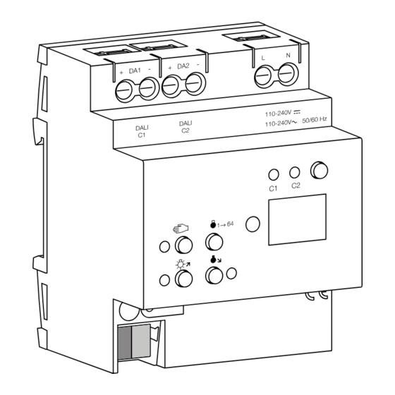
DALI Gateway 1 channel, DALI Gateway 2 channels Figure 3: DALI gateway connection example, 2fold ■ Attach the cover cap to the bus cable connection as protection against hazard- ous voltages. If the display (8) shows Er (error), an installation fault occurred that causes mains voltage to reach the DALI cable. - Page 12 DALI Gateway 1 channel, DALI Gateway 2 channels ues to be used with an unchanged DALI configuration (same short addresses, device types, group assignments, etc.). This is the case, for example, if a device is copied unchanged in the ETS project design or a configuration tem- plate is imported.
- Page 13 5 s. Restoring the device to factory settings The device can be reset to factory settings with the Hager/Berker Firmware Update App. This function uses the firmware contained in the device that was active at the time of delivery (delivered state). Restoring the factory settings causes the device to lose its physical address and configuration.
-
Page 14: Appendix
DALI Gateway 1 channel, DALI Gateway 2 channels Appendix Technical data KNX medium TP 256 KNX commissioning mode S mode Rated voltage KNX DC 21 ... 32 V SELV KNX current consumption 4.5 ... 5.0 mA Connection type for bus Device connection terminal Supply Rated voltage... -
Page 15: Troubleshooting
DALI Gateway 1 channel, DALI Gateway 2 channels Figure 5: Clampable cable cross-sections Installation width 72 mm / 4 HP Connection mode Screw terminal Connection torque for screw terminals Max. 0.8 Nm Troubleshooting Indication shows "Er", connected DALI devices have no function, no operation possible Cause: Mains voltage on DALI cable. - Page 16 Hager Controls S.A.S. B.P. 10140 Saverne Cedex France T +33 (0) 3 88 02 87 00 info@hager.com hager.com 2024-03...
Need help?
Do you have a question about the TYFS671D and is the answer not in the manual?
Questions and answers