
Related Manuals for hager TX216


Summary of Contents for hager TX216
- Page 1 KNX / EIB Product Documentation TX216 KNX/EIB DALI-Gateway Date of issue: 21.11.2006 64540020.111 Page 1 of 130...
-
Page 2: Table Of Contents
KNX / EIB Product Documentation Table of Contents Product definition ........................3 Product catalogue ........................3 Function ............................3 Fitting, electrical connection and operation ................4 Safety instructions........................4 Device components........................5 Fitting and electrical connection....................6 Commissioning........................10 Operation ..........................11 Technical data..........................18 Software description .........................20 Software specifications ......................20 "DALI Gateway C00Cx2"... -
Page 3: Product Definition
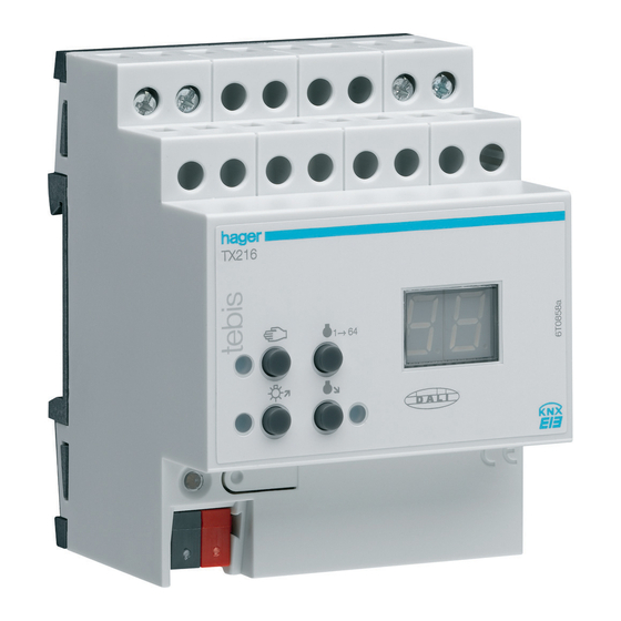
Product definition 1 Product definition 1.1 Product catalogue Product name: DALI Gateway Use: Gateway Design: REG (rail-mounted device) Order no.: 6 4540 020 1.2 Function The DALI Gateway represents the interface between a KNX/EIB installation and a digital DALI (Digital Addressable Lighting Interface) lighting system. -
Page 4: Fitting, Electrical Connection And Operation
Fitting, electrical connection and operation The functionalities that can be preset with the ETS independently for each lighting group include, for instance, separately parameterizable brightness ranges, extended feedback functions, disable function or, alternatively, a forced-control position function, separately adjustable dimming response, time delay and Staircase timer function with pre-warning and soft dimming functions. -
Page 5: Device Components
Fitting, electrical connection and operation 2.2 Device components ALL OFF D A L I OFF/ (1): KNX/EIB bus connection (2): Programming key and programming LED (red). The programming LED blinks slowly when the safe-state mode is active. (3): Screw terminals (L,N) for connection of mains voltage supply (4): Screw terminals (da+, da-) for connection of DALI line (5): 2-digit 7-segment display (red) for the display of the selected DALI group ("01"..."32"... -
Page 6: Fitting And Electrical Connection
Fitting, electrical connection and operation 2.3 Fitting and electrical connection DANGER! Electric shock in case of accidental contact with live parts. Electric shocks can be fatal. Before working on the device, cut out the mains supply and cover up live parts in the... - Page 7 Fitting, electrical connection and operation Connecting the device in order to supply the device electronics and the DALI interface with power Connect the mains voltage and the DALI system as shown in fig. 1 (connection example). ALL OFF DALI device .
- Page 8 Fitting, electrical connection and operation Removing other control facilities DALI devices from some manufacturers feature extended functions (operation with mains voltage at the DALI terminal). When using the DALI Gateway as a control unit in the DALI system, other existing control posts –...
- Page 9 Fitting, electrical connection and operation Installing / removing the protective cap To protect the bus lines against hazardous voltages, especially in the area of the connecting terminals, a protective cap can be installed. The cap is installed with the bus terminal in place and the connected bus line led out at the rear.
-
Page 10: Commissioning
Fitting, electrical connection and operation 2.4 Commissioning After installation of the Gateway and connection of the bus line and the mains supply as well as the DALI lines, the device can be put into operation. The following procedure is generally recommended... -
Page 11: Operation
Fitting, electrical connection and operation 2.5 Operation The DALI Gateway permits all lighting groups to be operated manually. The keypad features 4 function keys and 3 status LEDs on the front panel of the device that can be used to set the following modes of operation... - Page 12 Fitting, electrical connection and operation Controls and indicators for manual control ALL OFF OFF/ (5) (6) Fig. 4: Controls and indicators for manual control key: Activates / deactivates manual control (2) LED : LED ON indicates permanent manual control.
- Page 13 Fitting, electrical connection and operation Priorities The DALI Gateway distinguishes between different functions that can affect a DALI group. In order to prevent conflicting output states, each available function has been assigned a certain priority. The function with the higher priority overrides the one with the lower priority.
- Page 14 Fitting, electrical connection and operation Switching on the permanent manual control mode for broadcast Permanent manual control mode for broadcast has been activated. Press the key for at least 5 s - or - Switch off mains voltage supply.
- Page 15 Fitting, electrical connection and operation Deactivating the temporary manual control mode Temporary manual control mode has been activated. No key-press for 5 s - or - select all groups successively by a brief press of the key. Now press the key once more.
- Page 16 Fitting, electrical connection and operation Controlling a DALI group manually The DALI Gateway has been programmed at least once via the ETS. Manual control mode (permanent or temporary) has been activated. Select desired group: Press the key briefly (repeatedly, if necessary).
- Page 17 Fitting, electrical connection and operation DALI device replacement After the start of the automatic device replacement, the DALI Gateway can check the DALI system for the integrity of the DALI devices that have been previously put into operation. If, for instance, the installer has replaced a defect DALI electronic ballast device with a new one, the DALI Gateway is able to program the new electronic ballast device with the project data of the failed electronic ballast device.
-
Page 18: Technical Data
Technical data 3 Technical data Type of protection: IP 20 Safety class: Mark of approval: KNX / EIB / VDE Ambient temperature: -5 °C ... +45 °C Storage / transport temperature: -25 °C ... +70 °C (Storage above + 45 °C reduces the lifetime) - Page 19 Technical data DALI: Voltage: typically 16 V DC with over-voltage protection Current: typically 128 mA, max. 200 mA temporarily designed for a maximum of 64 DALI devices at 2 mA with short-circuit and overload protection Transmission rate 1200 bit/s Protocol: acc.
-
Page 20: Software Description
Software specifications 4 Software description 4.1 Software specifications ETS search paths: - Illumination / Dimmer / DALI Gateway BAU used: TPUART + µC KNX/EIB type class: 3b - device with cert. PhL + stack Configuration: S-mode standard PEI type: "00"... -
Page 21: Dali Gateway C00Cx2" Software
"DALI Gateway C00Cx2" software Scope of functions 4.2 "DALI Gateway C00Cx2" software 4.2.1 Scope of functions General: • Control of a maximum of 64 DALI devices in a max. of 32 groups. • Manual control of the groups independent of the bus (site operation with broadcast control). -
Page 22: Software Information
"DALI Gateway C00Cx2" software Software information 4.2.2 Software information ETS project design and commissioning For creating a project and for the commissioning of this device it is recommended to use the ETS3.0d version. Advantages with regards to downloading (significantly shorter loading times) can be expected only if this ETS patch version or later versions are used. -
Page 23: Object Table
"DALI Gateway C00Cx2" software Object table 4.2.3 Object table Number of communication objects: 216 Number of addresses (max): Number of assignments (max): Dynamic table management: Maximum table length: Objects affecting several channels: Function: Scenes Object Function Name Type DP type... - Page 24 "DALI Gateway C00Cx2" software Object table Function: DALI monitoring Object Function Name Type DP type Flag Message DALI voltage failure 1-bit 1.005 C, -, T, (R) Description: 1-bit object for reporting a mains voltage failure at the DALI Gateway.
- Page 25 "DALI Gateway C00Cx2" software Object table Channel-oriented objects: Function: Output switching Object Function Name Type DP type Flag Switching 0, 7, 14, … , 105 Group 1 ... 32 1-bit 1.001 C, W, -, (R) 112, 118, …, 202...
- Page 26 "DALI Gateway C00Cx2" software Object table Function: Staircase timer function Object Function Name Type DP type Flag 5, 12, 19, … , 110 Staircase timer Group 1 ... 16 1-bit 1.010 C, W, -, (R) function start/stop Description: 1-bit object for activating or deactivating the switching time of the Staircase timer function of an output ("1"...
-
Page 27: Functional Description
"DALI Gateway C00Cx2" software Functional description 4.2.4 Functional description 4.2.4.1 Application basics DALI The DALI Gateway represents the interface between a KNX/EIB building installation and a digital DALI (Digital Addressable Lighting Interface) lighting system. Normally, all DALI systems are room-oriented and deal with the high demands on functional light management in, for example, offices, training and conference rooms. - Page 28 "DALI Gateway C00Cx2" software Functional description Group 2 Lamp 11 Lamp 9 Lamp 7 Lamp 5 Lamp 10 Lamp 8 Lamp 6 Lamp 4 Lamp 3 Lamp 1 Group 1 Lamp 2 Group 3 Figure 5: Example of a grouping in the DALI system In the example of a grouping (cf.
- Page 29 "DALI Gateway C00Cx2" software Functional description The DALI Gateway acts as the central control component (master-controller) in the system that also ensures the power supply of the DALI interface. The DALI devices, e.g. DALI electronic ballast, function as slaves that transmit back the states or status reports to the master only upon request. It is the function of the DALI Gateway only to transmit control commands received by the KNX/EIB to the DALI line as well as to control the devices.
- Page 30 "DALI Gateway C00Cx2" software Functional description The communication via the DALI Gateway between the KNX/EIB and the DALI interface is bi- directional. On the one hand, the Gateway receives telegrams from the KNX/EIB that either directly influence the brightness status of a DALI group (e.g. by switching, dimming, setting the brightness value or scene recall) or indirectly adjust it (e.g.
- Page 31 "DALI Gateway C00Cx2" software Functional description ETS plug-in The setting of all device parameters as well as the DALI commissioning takes place entirely via the plug-in embedded in the ETS 3. The plug-in is part of the product database and will be automatically installed when the product file is imported into the ETS database.
- Page 32 "DALI Gateway C00Cx2" software Functional description Handling DALI groups: The DALI Gateway can distinguish up to 32 different groups which are created and configured separately. Group 1 has already been created in the start view of the plug-in. Additional groups can be added by selecting “Groups”...
- Page 33 "DALI Gateway C00Cx2" software Functional description Import, export, printing: The project design of the device (all parameter settings and KNX/EIB group addresses) as well as all DALI commissioning parameters (all detected DALI devices and group assignments) can be backed up by exporting an external XML file.
- Page 34 "DALI Gateway C00Cx2" software Functional description After the import has been confirmed the plug-in will ask whether the import is to take place with or without KNX/EIB group addresses (cf. figure 10). When importing without group addresses the plug-in will not transfer any associations between communication objects and group addresses of the XML file.
- Page 35 "DALI Gateway C00Cx2" software Functional description The plug-in of the DALI Gateway also permits the printing of the entire device configuration including the project design of the groups, the scene configuration and all DALI commissioning parameters in form of a configuration report.
-
Page 36: Functions Affecting Several Devices
"DALI Gateway C00Cx2" software Functional description 4.2.4.2 Functions affecting several devices Feedback for DALI error status The DALI Gateway permits the error status feedback of the connected DALI devices. In case of failure, the DALI components will send “lamp error” or “Error in device (e.g. electronic ballast error)” status information to the DALI Gateway where it will be stored. - Page 37 "DALI Gateway C00Cx2" software Functional description Setting the feedback for the DALI error status The ETS parameterization allows to define whether the error status feedback is to be transmitted actively to the KNX/EIB (telegram transmission when status has changed) or passively (telegram transmission only in case of a trigger request).
- Page 38 "DALI Gateway C00Cx2" software Functional description Feedback for the mains voltage supply on the DALI Gateway The DALI Gateway is able to monitor its supply voltage at the connection. In case of failure the Gateway is able to send a message telegram to the KNX/EIB before shutting down. Optionally, it is possible to have the mains voltage supply confirmed.
- Page 39 "DALI Gateway C00Cx2" software Functional description Feedback for DALI short-circuit The DALI Gateway detects short-circuits in the DALI line – for instance in case of an installation error. As soon as a short-circuit has been identified in the DALI line (with mains voltage applied), the DALI Gateway will send a feedback to the KNX/EIB if the feedback function has been enabled for a DALI short-circuit.
- Page 40 "DALI Gateway C00Cx2" software Functional description DALI device replacement After the start of the automatic device replacement, the DALI Gateway can check the DALI system for the integrity of the DALI devices previously put into operation. If, for instance, the installer has replaced a defect DALI electronic ballast device with a new one, the DALI Gateway is able to program the new electronic ballast device with the project data of the failed electronic ballast device.
- Page 41 "DALI Gateway C00Cx2" software Functional description Manual control The DALI Gateway permits to manually control all available DALI groups. The keypad with 4 function keys and 3 status LEDs on the front panel of the device can be used for setting the following modes of operation...
- Page 42 "DALI Gateway C00Cx2" software Functional description • A bus voltage failure will not terminate an active manual control even if the “Manual control in case of bus voltage failure = disabled” parameter has been set. It will be disabled only after ending manual control.
- Page 43 "DALI Gateway C00Cx2" software Functional description Set the "Behaviour at the end of permanent manual control during bus mode" parameter to "Retain outputs". During an active permanent manual control all incoming telegrams are internally tracked. At the end of the manual control mode, the groups will be set to the brightness states tracked last. If, however, a forced-control position or a disable function has been activated via the bus prior to or during manual control, the Gateway re-executes these higher-priority functions for the relevant groups.
- Page 44 "DALI Gateway C00Cx2" software Functional description Setting the status messaging function for the manual control mode The DALI Gateway can transmit a status message to the bus via a separate object with either activated or deactivated manual control mode. The status telegram can only be transmitted with the bus voltage switched on.
-
Page 45: Description Of Functions Affecting All Channels
"DALI Gateway C00Cx2" software Functional description 4.2.4.3 Description of functions affecting all channels: Delay after bus/ mains voltage return To reduce telegram traffic on the bus line after bus voltage activation (bus reset) or mains supply activation, after connecting the device to the bus line or after an ETS programming, it is possible to delay all actively transmitting feedback telegrams of the Gateway. - Page 46 "DALI Gateway C00Cx2" software Functional description Central function The Gateway provides the option to link selected individual or all groups with a 1-bit central communication object. The behaviour when activating a group via the central function is comparable to a central group address linked with all "Switching"...
-
Page 47: Channel-Oriented Functional Description
"DALI Gateway C00Cx2" software Functional description 4.2.4.4 Channel-oriented functional description • Each group can be separately parameterized in the plug-in. During the programming with the ETS, the individual DALI devices will be programmed with the parameter data of the assigned groups. All devices assigned to a DALI group will be put into operation in the exact same way. - Page 48 "DALI Gateway C00Cx2" software Functional description Setting the minimum brightness The minimum brightness can be set separately for each DALI group. Set the “Minimum brightness” parameter in the “Groups- [x] group name" parameter node (x = group number 1...32) to the required brightness value.
- Page 49 "DALI Gateway C00Cx2" software Functional description Setting the switch-on brightness The switch-on brightness can be set separately for each DALI group. Set the “Switch-on brightness” parameter in the “Groups - [x] group name" parameter node (x = group number 1...32) to “Brightness value”. Select the required brightness value in the selection field.
- Page 50 "DALI Gateway C00Cx2" software Functional description Response to bus voltage failure, bus or mains voltage return or ETS programming The switching states or brightness values of the DALI groups following bus voltage failure, bus or mains voltage return or after ETS programming can be set separately.
- Page 51 "DALI Gateway C00Cx2" software Functional description Setting the response to bus voltage failure The “Response to bus voltage failure” parameter is created separately for each group in the “Groups - [x] group name" parameter node (x = group number 1...32).
- Page 52 "DALI Gateway C00Cx2" software Functional description Set the parameter to "Start Staircase timer function". Independent of the “Switching” object, the Staircase timer function will be activated after bus voltage return. Make sure that the Staircase timer function has been enabled in the parameterization of the plug-in.
- Page 53 "DALI Gateway C00Cx2" software Functional description Additional functions Additional functions can be enabled for each DALI group.. A disable function or, alternatively, a forced- control position function can be configured to serve as an additional function. Only one of these functions can be enabled for an group.
- Page 54 "DALI Gateway C00Cx2" software Functional description Set the "Response at the beginning of the disable function" parameter in the "Groups - [x] group name" parameter node to the required behaviour. At the beginning of the disable, the parameterized behaviour will be executed and the bus control of the group will be locked.
- Page 55 "DALI Gateway C00Cx2" software Functional description Setting the forced-control position function as an additional function As shown on the functional diagram (cf. Fig. 15), the forced-control position function can also be combined with other functions of a group. In case of an active forced-control position function, the upstream functions are overridden so that the affected group will be locked.
- Page 56 "DALI Gateway C00Cx2" software Functional description Set the “Type of additional function” parameter in the “Groups - [x] group name" parameter node (x = group number 1...32) to “Forced-control position function”. The forced-control position function is now enabled. The "Forced-control position " communication object and the parameters of the forced-control position function become visible.
- Page 57 "DALI Gateway C00Cx2" software Functional description Set the "Response to bus voltage return" parameter in the "Groups - [x] group name" parameter node to the required behaviour. After bus or mains voltage return, the parameterized state will be adopted in the "Forced-control position"...
- Page 58 "DALI Gateway C00Cx2" software Functional description Feedback for switching status and brightness value: The DALI Gateway can track the current switching status and brightness value of a DALI group via separate feedback objects. It can also transmit them to the bus if the bus voltage has been switched The following feedback objects can be independently enabled for each DALI group...
- Page 59 "DALI Gateway C00Cx2" software Functional description Object "Disable" / "Forced-control" Staircase timer Object function "staircase timer (timing) function start/stop" Object Polarity of "Central function" central object Behaviour - bus voltage failure Object additional function Group Time functions Soft-ON / OFF...
- Page 60 "DALI Gateway C00Cx2" software Functional description Setting switching status feedback on return of bus/ mains voltage or after programming with the ETS If used as an active message object, the switching status feedback information is transmitted to the bus after bus voltage return or after programming with the ETS.
- Page 61 "DALI Gateway C00Cx2" software Functional description Activating brightness value feedback The brightness value feedback can be used as an active message object or as a passive status object. In case of an active message object the brightness value feedback telegram will also be directly transmitted to the bus after each update.
- Page 62 "DALI Gateway C00Cx2" software Functional description Setting the cyclical transmission function for the brightness feedback telegram In addition to being transmitted in case of an update, the brightness value feedback telegram can also be transmitted cyclically via the active message object.
- Page 63 "DALI Gateway C00Cx2" software Functional description Dimming response and dimming speeds The brightness for the devices of a DALI group can be changed by a dimming operation. The available range of brightness is defined by the maximum and minimum brightness provided by the ETS (cf.
- Page 64 "DALI Gateway C00Cx2" software Functional description • Even if brightness values are instantly jumped to the dimming will take a short time with the DALI devices of a group. This applies also to the switching without the Soft-ON or – OFF function. This dimming procedure depends on the system.
- Page 65 "DALI Gateway C00Cx2" software Functional description The characteristic dimming curve shown in figure 18 is logarithmic – as it is common in a DALI system. Thus, the brightness behaviour of the DALI lights during the dimming will adjust to the sense of brightness of the human eye.
- Page 66 "DALI Gateway C00Cx2" software Functional description Automatic shutoff The shutoff function permits the automatic shutoff of a DALI group after the light intensity has been dimmed to a brightness value or jumped to and after this new brightness value falls below a shutoff brightness adjusted in the ETS.
- Page 67 "DALI Gateway C00Cx2" software Functional description The shutoff function can also be combined with other functions of the DALI Gateway. In this case make sure that the disable function, the forced-control position function or the scene function will override the shutoff function (cf.
- Page 68 "DALI Gateway C00Cx2" software Functional description Setting the shutoff brightness The shutoff function requires the definition of the shutoff brightness. The shutoff brightness is set separately for each DALI group. The shutoff function must be enabled. Set the “Shutoff when brightness value is smaller” parameter in the "Groups - [x] group name - dimming"...
- Page 69 "DALI Gateway C00Cx2" software Functional description Time delays Up to two time functions can be independently set for each DALI group. The time functions act solely on the "Switching" or "Switching central function" communication objects (if a central has been activated for the affected output) and will delay the received object value as a function of telegram polarity (cf.
- Page 70 "DALI Gateway C00Cx2" software Functional description Activating an OFF-delay The Off-delay can be activated separately for each group in the plug-in of the DALI Gateway. Set the "Selection of time delay" parameter in the “Groups - [x] group name – Switch-on/switch-off behaviour"...
- Page 71 "DALI Gateway C00Cx2" software Functional description Soft-ON/OFF function The Soft functions permit the slowed- down switching on or off of a DALI group if a switching command is received via the “Switching” or “Switching central function” communication objects. If a Soft-ON function is activated, dimming will be executed until the parameterized switch-on brightness has been reached.
- Page 72 "DALI Gateway C00Cx2" software Functional description Figure 23 shows the functional diagram of the Soft functions. The Soft functions will also affect the switching edges of the Staircase timer function. Object "Disable" / "Forced-control" Staircase timer Object function "staircase timer (timing) function start/stop"...
- Page 73 "DALI Gateway C00Cx2" software Functional description Setting and enabling the Soft-OFF function The Soft-OFF function can be set separately for each group in the plug-in of the DALI Gateway. Set the “Soft-OFF function” parameter in the “Groups - [x] group name – Switch-on/ switch-off behaviour"...
- Page 74 "DALI Gateway C00Cx2" software Functional description Staircase timer function The Staircase timer function that can be parameterized separately can be used for implementing time- controlled staircase lighting or functionally similar applications. The Staircase timer function must have been enabled in the "Groups - [x] group name – Staircase timer function" parameter node to make the required communication objects and parameters visible.
- Page 75 "DALI Gateway C00Cx2" software Functional description Defining the switch-on behaviour of the Staircase timer function An ON-telegram to the "Staircase timer start / stop" object activates the staircase lighting time (T ) the duration of which is defined by the "Staircase lighting time" parameter. The DALI group switches to switch-on brightness.
- Page 76 "DALI Gateway C00Cx2" software Functional description Set the “Staircase timer function ?” parameter in the “Groups - [x] group name – Staircase timer function" parameter node to “Yes”. The Staircase timer function is now enabled. Other parameters will become visible.
- Page 77 "DALI Gateway C00Cx2" software Functional description In addition, the switch-off can be influenced by the Soft functions of the DALI Gateway. With a possible Soft-ON-delay and Soft-OFF delay function, the Staircase timer function has the switch-off behaviour as shown in Fig. 28.
- Page 78 "DALI Gateway C00Cx2" software Functional description Setting the pre-warning function of the Staircase timer function The pre-warning function complies with DIN 18015-2 and is intended to alert anyone present in the staircase that the lights will go out shortly. The devices of the affected DALI group can be set to a pre- warning brightness before the group shuts off completely.
- Page 79 "DALI Gateway C00Cx2" software Functional description The Staircase timer function must be enabled. Set the "Activate pre-warning time ?" parameter in the "Groups - [x] group name – Staircase timer function " parameter node to "Yes". The pre-warning function is now enabled. The desired pre-warning time (T ) can now be set.
-
Page 80: Scene Function
"DALI Gateway C00Cx2" software Functional description 4.2.4.5 Scene function The DALI Gateway permits the creation of up to 16 scenes of its own. Each scene can be assigned an available DALI group. A scene brightness value can also be parameterized and stored in the DALI Gateway for each assigned group. - Page 81 "DALI Gateway C00Cx2" software Functional description Created scenes can be deleted at any time by selecting a scene and executing the “Delete” command in the context menu. Each scene can be assigned a name. The scene must be selected and opened via the “Rename”...
- Page 82 "DALI Gateway C00Cx2" software Functional description Configuring the group assignment of a scene All groups can be assigned to a scene without any restrictions. Each group can be independently assigned by activating the check box in front of the scene configuration (cf. Figure 33). Groups that have not been activated by the check box are not assigned to the scene.
- Page 83 "DALI Gateway C00Cx2" software Functional description Setting the storage behaviour for the scene function Upon reception of a storage telegram the current brightness values for all the DALI groups assigned to a scene can be internally stored via the scene extension object. The brightness values to be stored prior to the storing can be influenced by all functions of the individual groups (e.g.
- Page 84 "DALI Gateway C00Cx2" software Functional description • Independent of the set scene priority with enabled scene memory function, no new scene values will be stored for an assigned group if a disable or a forced-control position has been activated in this group! •...
- Page 85 "DALI Gateway C00Cx2" software Functional description Setting a scene recall delay for the scene function Optionally, the evaluation of each scene recall can also be delayed. This allows, for example to have dynamical scene sequences to be configured in combination with several actuators or Gateways with cyclical scene telegrams.
- Page 86 "DALI Gateway C00Cx2" software Functional description Setting the response to a scene recall A scene can be configured whether the light intensity dims to or instantly jumps to the scene brightness values for the assigned groups. Thus a scene recall can be executed independent of the adjusted dimming response of the groups.
-
Page 87: Dali Commissioning
"DALI Gateway C00Cx2" software Functional description 4.2.4.6 DALI commissioning Starting the DALI commissioning The plug-in embedded in the ETS 3 makes it easy to configure the DALI Gateway as well as to create and parameterize the required DALI groups. Also, the plug-in allows the DALI to be commissioned via the KNX/EIB bus line. - Page 88 "DALI Gateway C00Cx2" software Functional description In case a connection link to the DALI Gateway can not be established in this situation, the plug-in will abort the commissioning prematurely and will not show the commissioning environment. The following lists the possible causes for a faulty connection and their corresponding remedies...
- Page 89 "DALI Gateway C00Cx2" software Functional description The commissioning environment of the plug-in is divided into two windows. The left window lists the devices found in the DALI system. The right window displays the created groups. This is where the DALI devices are assigned to the groups.
- Page 90 "DALI Gateway C00Cx2" software Functional description Figure 37: Example of a device list after search has been completed (in this case two new electronic ballast devices) • The DALI Gateway will not detect an error in the DALI line during a device search. In case of a short- circuit, for example, the Gateway will attempt to establish a cyclical DALI communication.
- Page 91 "DALI Gateway C00Cx2" software Functional description Figure 38: Assigning a name to identified devices • The short address of a device shown in square brackets in front of the device name cannot be edited. • The short addresses of the identified devices are assigned randomly. Several test functions available in the plug-in can be used to detect during the name assignment which device is actually identified in the list entry.
- Page 92 "DALI Gateway C00Cx2" software Functional description Select the required group that will have devices assigned to them from the right subwindow. Figure 39: Selecting a group Assign one or several available DALI devices to the group. The assigned devices will be removed from the list box in the left subwindow and will appear for the selected group in the right window (cf.
- Page 93 "DALI Gateway C00Cx2" software Functional description If applicable, select another group from the right subwindow. All available devices will again become visible in the left subwindow if no assignment has yet been made for the selected group. Again, assign one or several available DALI devices to the group.
- Page 94 "DALI Gateway C00Cx2" software Functional description • The “Default” button will reset all commissioning parameters. Assignments of DALI devices to groups get lost from the project design and the DALI Gateway if the “Default” button in the commissioning environment has been activated!
- Page 95 "DALI Gateway C00Cx2" software Functional description Figure 42: Synchronising the commissioning parameters between plug-in and DALI device Close the plug-in in order to complete the commissioning and to accept all required parameter settings. Then re-program the application program of the DALI Gateway with the ETS 3 (cf. Chapter 2.4 “Commissioning”).
-
Page 96: Dali Test
"DALI Gateway C00Cx2" software Functional description 4.2.4.7 DALI test Starting the DALI test The plug-in of the DALI Gateway provides several options for a complete and comprehensive test of the DALI installation. It is possible to address and to switch individual devices during the device- oriented DALI test after a DALI commissioning and to read-out or preset brightness values. - Page 97 "DALI Gateway C00Cx2" software Functional description When opening the test environment the plug-in first attempts to communicate with the DALI Gateway via the bus connection of the ETS and verifies whether a DALI test is possible. For this reason the DALI Gateway must be connected to the KNX/EIB and the bus and the mains voltage supply must be switched on if the DALI test is to be called up.
- Page 98 "DALI Gateway C00Cx2" software Functional description The selected device can then independently be switched on or switched off. In addition, it is possible to preset an absolute brightness value. When activating the “Set value” button the brightness value selected in the drop-down menu will be transmitted to the applicable device which should immediately accept this brightness value.
- Page 99 "DALI Gateway C00Cx2" software Functional description Group-oriented DALI test The group-oriented DALI test can be executed once the groups have been created and parameterized in the device configuration and once the DALI commissioning including group assignments of the devices has been completed. Activate the “Test DALI groups” button in the DALI test environment. The group-oriented test environment will then open (cf.
- Page 100 "DALI Gateway C00Cx2" software Functional description In addition, the devices of the group can be dimmed by a relative dimming operation. A relative dimming operation is initiated by activating the “Start” button. Starting at the current brightness value the dimming proceeds with the parameterized dimming speed within the brightness range specified for the group.
- Page 101 "DALI Gateway C00Cx2" software Functional description Scene-oriented DALI test The scene-oriented DALI test can be executed once the groups have been created and parameterized in the device configuration and once the DALI commissioning including group assignments of the devices has been completed. Activate the “Test DALI scenes” button in the DALI test environment. The scene-oriented test environment will then open (cf.
- Page 102 "DALI Gateway C00Cx2" software Functional description The brightness values pre-defined in the scene configuration (parameter page “Scene”) become visible in the corresponding drop-down menus of the groups when the scene-oriented DALI tests are started. By activating the “Recall scene” button, a scene will be recalled with the brightness values that have been pre-defined during the scene configuration.
-
Page 103: Delivery State
"DALI Gateway C00Cx2" software Functional description 4.2.4.8 Delivery state In the delivery state the device behaves passively, i.e. no telegrams will be transmitted to the bus. A collective control of the connected DALI devices via the manual control broadcast on the device is possible if connected to the mains voltage. -
Page 104: Parameters
"DALI Gateway C00Cx2" software Parameters 4.2.5 Parameters Description: Values: Remarks: General DALI error status Yes, feedback object is active The error status of the DALI devices can be feedback ? message object reported to the bus. Setting "Yes" activates... - Page 105 "DALI Gateway C00Cx2" software Parameters Enable DALI device After the start of the automatic device replacement manually ? replacement, the DALI Gateway can check the DALI system via manual control for the integrity of the DALI devices incorporated in the system. Thus, the DALI Gateway is...
- Page 106 "DALI Gateway C00Cx2" software Parameters Manual control Manual control in case of Disabled In case of a bus voltage failure (bus voltage bus voltage failure switched off) you can determine whether Enabled manual control is to be enabled or disabled.
- Page 107 "DALI Gateway C00Cx2" software Parameters Function and polarity of This parameter specifies the information status object contained in the status object. The object will always be "0" if the manual control has been deactivated. 0 = inactive; 1 = manual The object will be "1"...
- Page 108 "DALI Gateway C00Cx2" software Parameters Groups Time for the cyclical 00:00:10 … 23:59:59 Depending on the parameterization, all transmission of the [hh:mm:ss] active feedback telegrams of the Gateway feedback telegram 20 s can transmit their status also cyclically to the bus.
- Page 109 "DALI Gateway C00Cx2" software Parameters [x] Group (x = 1 … 32) The name of the group can be edited and will be displayed in the node.. Name 0 … 28 characters The group can be assigned a unique name (e.g.
- Page 110 "DALI Gateway C00Cx2" software Parameters Maximum brightness 30 % This parameter will set the maximum 35 % brightness of the DALI group will be set. 40 % The parameterized value will not be 45 % exceeded regardless of the operating state 50 % of the Gateway.
- Page 111 "DALI Gateway C00Cx2" software Parameters Switch-on brightness This parameter determines the brightness value that the group is adjusted to each time there is a switch-on via the “Switching” or “Switching central function” object. When switching on, the group will be...
- Page 112 "DALI Gateway C00Cx2" software Parameters Response to bus voltage The Gateway permits to set separately the failure brightness value for each DALI group after a bus voltage failure. The group will be switched off. Switch-off The group will be adjusted to the...
- Page 113 "DALI Gateway C00Cx2" software Parameters Response to bus voltage The Gateway permits to separately set the return brightness value for each DALI group after bus or mains voltage return separately. The group will be switched off. Switch-off The group will be adjusted to the...
- Page 114 "DALI Gateway C00Cx2" software Parameters Polarity of disable object This parameter defines the polarity of the 0 = enabled / 1 = disabled disable object. 1 = enabled / 0 = disabled • The disable function will always be deactivated (object value “0”) after a bus...
- Page 115 "DALI Gateway C00Cx2" software Parameters Response at the The behaviour of the DALI group at the beginning of the disable beginning of the disable function can be function parameterized. Switch-off At the beginning of the disable the group will be switched off and locked.
- Page 116 "DALI Gateway C00Cx2" software Parameters Response at the end of The behaviour of the DALI group at the end the disable function of the disable function can be parameterized. Switch-off At the end of the disable the group will switched off and re-enabled.
- Page 117 "DALI Gateway C00Cx2" software Parameters Response at the end of Memory value (brightness At the end of the disable, the value will be the disable function prior to the last shutoff) adjusted to the brightness value that was (continued) active and internally stored prior to the last switch-off (via the “Switching”...
- Page 118 "DALI Gateway C00Cx2" software Parameters Response to bus voltage The communication object of the forced- return control position function can be initialized after bus voltage return. The brightness status of the DALI group can be influenced if the forced-control position function is activated.
- Page 119 "DALI Gateway C00Cx2" software Parameters Brightness for forced- If the forced-control position is active and a control position active, forced switching is “ON”, the parameter will determine the behaviour of the Group’s DALI devices. The group will be adjusted to the...
- Page 120 "DALI Gateway C00Cx2" software Parameters Switching Switching status The current switching state of the DALI feedback ? group can be reported back separately to the bus. Yes, feedback object is active Feedback and object are activated. The message object status is transmitted in non-inverted form.
- Page 121 "DALI Gateway C00Cx2" software Parameters Assignment to central This parameter determines the assignment function ? of the DALI group to the central function. The group is assigned to the central function. The group is not assigned to the central function.
- Page 122 "DALI Gateway C00Cx2" software Parameters Dimming Time for relative dimming 00:00:01 … 05:59:59 This parameter will set the relative time (0...100%) [hh:mm:ss] increments (4-bit dimming). The time entered defines the maximum duration for the dimming across the entire brightness range from 0 % to 100 % brightness.
- Page 123 "DALI Gateway C00Cx2" software Parameters Delay until shutoff ? This parameter activates the delay time of the automatic shutoff function. After the delay time has lapsed the DALI group will shut off if the shut-off brightness has been reached or under-run at the end of a dimming operation.
- Page 124 "DALI Gateway C00Cx2" software Parameters Cyclical transmission of The object value of the feedback can be feedback telegram ? transmitted in cycles. Yes (cyclical transmission and The feedback telegram is transmitted to the transmission in case of bus in cycles and after a change of status.
- Page 125 "DALI Gateway C00Cx2" software Parameters Switch-on/switch-off behaviour Selection of time delay The “Switching” and “Switching central None function” communication objects can be ON-delay separately evaluated. This parameter is used to define the desired mode of operation of the time delay and to enable OFF-delay the other delay parameters.
- Page 126 "DALI Gateway C00Cx2" software Parameters Time for Soft-ON 00:00:01 … 23:59:59 This parameter determines the dimming (0...100%) [hh:mm:ss] increment time for the Soft-ON function. The time entered defines the maximum duration for the Soft-ON dimming across the entire brightness range from 0 % to 100 % brightness.
- Page 127 "DALI Gateway C00Cx2" software Parameters Staircase timer function (applies only to DALI groups 1...16!) Staircase timer function This parameter can enable the Staircase timer function and the corresponding communication objects. Staircase lighting time 00:00:01 … 23:59:59 This parameter is used for programming [hh:mm:ss] the duration of the Staircase timer function.
- Page 128 "DALI Gateway C00Cx2" software Parameters Reduced brightness 0.1 % … 100 %; 10 % This parameter determines the reduced during pre-warning time brightness to be adjusted at the time of the pre-warning. • The adjustable value is restricted by the parameterized minimum and maximum brightness.
- Page 129 "DALI Gateway C00Cx2" software Parameters Scenes [x] Scene (x = 1 … 16) The name of the scene can be edited and will be displayed in the node. Name 0 … 28 characters At this point the scene can be assigned a unique name (e.g.
- Page 130 "DALI Gateway C00Cx2" software Parameters Overwrite scene values During storage of a scene, the scene during ETS download ? values (current brightness values of the affected groups) are stored internally in the device. To prevent the stored values from...
Need help?
Do you have a question about the TX216 and is the answer not in the manual?
Questions and answers