Advertisement
Quick Links
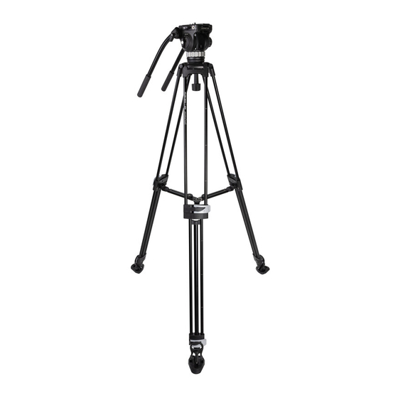
Congratulations on your purchase of this ProMaster 30P Video Tripod Kit. Please read these instructions
thoroughly to ensure proper assembly, operation, and adjustment of your new tripod kit. With proper use and
adjustments, your 30P Video Tripod Kit will provide many years of excellent service.
ASSEMBLY:
Attaching the Handles
The 30P includes two Handles (5) for your convenience. You can mount one or both. Simply connect each handle
to the head of the tripod using its Handle Connection Ports (6). Each handle has a knob for making this
connection. While installing each handle you can also choose the best angle for a comfortable grip.
Installing the Removable Platforms
The 30P comes with Removable Platforms (16) preinstalled on its Spiked Feet (15). The Removable Platforms
may become dislodged in shipping. To install them properly, rotate the Platform Handle (17) toward the front of
the Platform, and place the Spiked Feet (15) on the Removable Platform (16) as shown in Figure 1. Then, pull the
Platform Handle up and back so that it comes over the front spike as shown in Figure 2. It is easiest to do this
with the Tripod legs spread and placed on the ground, using one hand to hold the leg steady while the other
manipulates the Platform Handle. To deinstall the Removable Platforms (16), reverse this procedure.
Understanding the Bowl System and Flat Base
A 75mm half-ball comes preattached to the flat base (bottom) of the head and works with a bowl that is
integrated into the collar of the tripod for leveling the head. It is highly recommended that you check the
connection between the half-ball and the base of the head before use to be sure it is tight. To do this, begin by
loosening and removing the Bowl Handle (20) followed by lifting the head and half-ball out of the top of the
tripod. (Do all of this without a camera attached.) Turn the head upside down so that you are looking at the
bottom of the half-ball. Notice the 3 Grub Screws (19). Check all 3 of these screws to ensure they are tight using a
3mm hex wrench (included). If the screws are not tight, you can reinstall the half-ball by loosening all 3 screws,
taking hold of the half-ball, turning it clockwise until it is tight against the flat base of the head, and then
tightening all 3 Grub Screws (19). Replace the head and half-ball into the top collar of the tripod and reattach the
Bowl Handle (20).
The 30P uses a flat base for its head with a common 3/8"-16 threaded port in the center of that base. This flat
base allows you to mount the head on other tripods, sliders, and apparatus for a variety of video techniques.
When you need to mount the head to another apparatus, remove it from the tripod by loosening and removing
the Bowl Handle (20). Then, turn the head over and loosen all 3 Grub Screws (19). Finally, remove the half-ball
from the head by turning it counterclockwise. Do these steps in reverse order to reinstall the head onto the
tripod.
Mounting the Quick Release Plate to Your Camera
Locate the Quick Release Plate (1). The plate has two camera attachment screws, a 1/4"-20 screw and a 3/8"-16
screw. You can use one, or both, of the screws to mount your camera (or lens), depending on what size and type
of mounting ports are available on your gear. If you have the ability to use both screws, it is recommended to do
Advertisement

Subscribe to Our Youtube Channel
Related Manuals for Promaster 30P


Summary of Contents for Promaster 30P
- Page 1 Congratulations on your purchase of this ProMaster 30P Video Tripod Kit. Please read these instructions thoroughly to ensure proper assembly, operation, and adjustment of your new tripod kit. With proper use and adjustments, your 30P Video Tripod Kit will provide many years of excellent service. ASSEMBLY: Attaching the Handles The 30P includes two Handles (5) for your convenience. You can mount one or both. Simply connect each handle to the head of the tripod using its Handle Connection Ports (6). Each handle has a knob for making this connection. While installing each handle you can also choose the best angle for a comfortable grip. Installing the Removable Platforms The 30P comes with Removable Platforms (16) preinstalled on its Spiked Feet (15). The Removable Platforms may become dislodged in shipping. To install them properly, rotate the Platform Handle (17) toward the front of the Platform, and place the Spiked Feet (15) on the Removable Platform (16) as shown in Figure 1. Then, pull the Platform Handle up and back so that it comes over the front spike as shown in Figure 2. It is easiest to do this with the Tripod legs spread and placed on the ground, using one hand to hold the leg steady while the other manipulates the Platform Handle. To deinstall the Removable Platforms (16), reverse this procedure. Understanding the Bowl System and Flat Base A 75mm half-ball comes preattached to the flat base (bottom) of the head and works with a bowl that is integrated into the collar of the tripod for leveling the head. It is highly recommended that you check the connection between the half-ball and the base of the head before use to be sure it is tight. To do this, begin by loosening and removing the Bowl Handle (20) followed by lifting the head and half-ball out of the top of the tripod. (Do all of this without a camera attached.) Turn the head upside down so that you are looking at the bottom of the half-ball. Notice the 3 Grub Screws (19). Check all 3 of these screws to ensure they are tight using a 3mm hex wrench (included). If the screws are not tight, you can reinstall the half-ball by loosening all 3 screws, taking hold of the half-ball, turning it clockwise until it is tight against the flat base of the head, and then tightening all 3 Grub Screws (19). Replace the head and half-ball into the top collar of the tripod and reattach the Bowl Handle (20). The 30P uses a flat base for its head with a common 3/8”-16 threaded port in the center of that base. This flat base allows you to mount the head on other tripods, sliders, and apparatus for a variety of video techniques. When you need to mount the head to another apparatus, remove it from the tripod by loosening and removing the Bowl Handle (20). Then, turn the head over and loosen all 3 Grub Screws (19). Finally, remove the half-ball from the head by turning it counterclockwise. Do these steps in reverse order to reinstall the head onto the tripod. Mounting the Quick Release Plate to Your Camera Locate the Quick Release Plate (1). The plate has two camera attachment screws, a 1/4”-20 screw and a 3/8”-16 screw. You can use one, or both, of the screws to mount your camera (or lens), depending on what size and type of mounting ports are available on your gear. If you have the ability to use both screws, it is recommended to do...
-
Page 2: Mounting Your Camera
Note: The Quick Release Plate (1) does not have a front or back and can be mounted in either direction with no impact on functionality. An anti-twist pin is also found in the Quick Release Plate (1). This pin works with a small hole found in the base of some cameras. If your gear does not have this hole and you mount the QR plate, the pin will simply move out of the way thanks to its spring-type back. The anti-twist pin can also be removed from the plate with a Phillips-head screwdriver. Mounting Your Camera Once the Quick Release Plate (1) is securely fastened to your camera or lens, you are ready to mount it to the tripod. Loosen the Quick Release Knob (3) and, using a forward motion, slide the plate onto the head from the back. Keeping the Quick Release Button (4) depressed while doing so can make this process easier but is not necessary for mounting. Once you are sure that a solid connection has been made, tighten the Quick Release Knob (3) before releasing the camera. This quick release system is designed to slide and be repositionable along the length of the plate so that you can find the best balance point for your gear. When properly balanced, the tripod head will operate at its best and your gear will be safest; an out-of-balance rig can tip over. Note: When the Quick Release button (4) is released (not pushed in), a safety catch should prevent the camera from accidentally sliding out of the head when the Quick Release Knob (3) is loosened. However, you should always keep a strong hold on your camera and lens for extra security to prevent it from falling when the Quick Release Knob (3) is loosened. To remove your camera, grasp it securely, loosen the Quick Release Knob (3), and then press and hold the Quick Release Button (4) while you slide the camera out of the head. OPERATION: Adjusting and Extending the Legs Use the Flip Locks (14) to adjust the length of each leg. Flip the silver tab from right to left (while facing the leg) to open the lock. Flip it back, from left to right, to close the lock. When a lock is loose, you can freely move the leg by extending or retracting it. These Flip Locks make it easy to rapidly deploy or collapse the tripod’s legs, as there are no knobs that need to be loosened or tightened. For times when the tripod is not set to its maximum height, extend the middle section before the lower sections—using the middle sections first will increase stability. Each leg has height lines (18) etched into its tubes. These serve as a visual guide to help you adjust each leg to the same height when that is the goal. You can adjust the angle of each leg by using the Spreader (12). Notice the 3 Spreader Locks (13). Each lock can be independently loosened to change the angle of the attached leg and then tightened to hold that angle. This is a great way to help level your tripod on uneven terrain. The Spreader (12) features scale marks on each of its 3 sections, making it easy to achieve consistent leg angle adjustments. When maximum stability is needed, adjust every leg to its widest angle. This ultra-wide stance will reduce the maximum possible height of the tripod, yet it will achieve the best possible stability. Note: The Spreader (12) can be detached and replaced if broken. If you need a replacement, contact ahuman@promaster.com or visit your local ProMaster retailer. To detach the Spreader (12), pinch the two release buttons where each arm connects to the tripod’s legs and slide the arm down; to install a replacement, reverse this process. Never operate the tripod without the Spreader (12) securely installed. - Page 3 Operating the Head Loosen the Pan Lock (9) to allow a rotational movement of the head and camera. Or, tighten this knob to lock this head into a specific position along its rotation. The Pan Drag (10) allows you to set the amount of resistance to the panning movement when the Pan Lock (9) is unlocked. Turn the Pan Drag (10) dial in a left direction (oriented with the tripod upright and facing you) to apply more resistance and turn it in a right direction to apply less. Even with the Pan Drag set to its minimum you will feel some resistance in this motion. This is designed as such to help create smooth, fluid-like movements. As with panning, two knobs are used for the tilting movement of the head. The Tilt Lock (7) works similarly to the Pan Lock (9) by either unlocking this motion or locking it into a fixed position. The Tilt Drag (8) allows you to set the amount of resistance to the tilting movement of the head when the Tilt Lock (7) is unlocked. Turn the Tilt Drag (8) knob clockwise to apply more resistance and counterclockwise to apply less. Even with the tilt drag set to its minimum you will feel some resistance in this motion. Note: It is important for the camera to be properly balanced on the head (using the QR Plate’s sliding design) for the tilt to work properly. If the camera rig is out of balance, the tilt will not provide smooth movements. Note: For best results, fully tighten and loosen the Tilt Drag (8) and Pan Drag (10) 2-3 times before using the 30P for the first time. Using the Accessory Ports Two Accessory Ports (2) are located on the tripod head. One port is a 3/8”-16 thread and the other, smaller port has a 1/4”-20 thread size. Use these to connect accessories such as flex arms, spigots, lights, microphones, etc. PRECAUTIONS: 1) Ensure all Flip Locks (14) are tightened before mounting a camera. 2) Check that the Spreader Locks (13) are tightened before mounting a camera. 3) Never operate the tripod without the Spreader (12) securely installed. 4) Lock the Pan Lock (9) and Tilt Lock (7) before mounting a camera. 5) Make sure the bowl system is leveled and locked in place before mounting a camera. 6) Always hold on to the camera when loosening the Quick Release Knob (3) for mounting or removing the camera. 7) Do not exceed the maximum load capacity (13.25 lbs / 6kg) of this tripod kit. This includes the weight of any accessories mounted to your camera and to the Accessory Ports (2). 8) This tripod kit is not waterproof. Do not submerge it or expose it to wet conditions.
-
Page 4: Parts Diagram
PARTS DIAGRAM: Quick Release Plate Quick Release Knob Accessory Ports Handle Connection Ports Tilt Lock Pan Drag Handles Bowl Handle Height Lines Spreader Spreader Locks Flip Locks Removable Platforms Height Lines Spiked Feet Removable Platforms Platform Handle... - Page 5 PARTS DIAGRAM: Quick Release Button Accessory Ports Quick Release Plate Handles Tilt Drag Pan Drag Handle Connection Ports Pan Lock Grub Screws Bubble Level...
- Page 6 PARTS DIAGRAM: Platform Handle Spiked Feet Removable Platforms INSTALLING THE REMOVABLE PLATFORMS Figure 1 Figure 1 Figure 2 Figure 2...
- Page 7 ONE YEAR UNCONDITIONAL WARRANTY If for any reason, this ProMaster product fails within ONE YEAR of the date of purchase, return this product to your ProMaster dealer and it will be exchanged for you at no charge. ProMaster products are guaranteed for ONE FULL YEAR against defects in workmanship and materials. If at any time after one year, your ProMaster product fails under normal use, we invite you to return it to ProMaster for evaluation. Code 68734 Made in China WWW.PROMASTER.COM...
Need help?
Do you have a question about the 30P and is the answer not in the manual?
Questions and answers