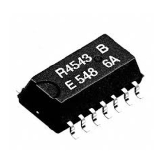
Summary of Contents for Epson Q41454351000200
- Page 1 MQ252-04 Application Manua Real Time Clock Module RTC-4543SA Model Product Number RTC-4543SA Q41454351000200 RTC-4543SB Q41454361000200...
- Page 2 • The information, applied circuit, program, using way etc., written in this material is just for reference. Seiko Epson does not assume any liability for the occurrence of infringing any patent or copyright of third party. This material does not authorize the licence for any patent or intellectual property rights.
-
Page 3: Table Of Contents
RTC - 4543 SA/SB CONTENTS 1. OVERVIEW ......................1 2. BLOCK DIAGRAM ................... 1 3. PIN CONNECTIONS ..................2 4. PIN FUNCTIONS ..................... 2 5. ELECTRICAL CHARACTERISTICS ............3 5-1. A BSOLUTE AXIMUM ATINGS ..................3 5-2. O PERATING ONDITION....................... 3 5-3. -
Page 4: Overview
RTC - 4543 SA/SB 32-kHz Output Serial RTC Module RTC - 4543 SA/SB Built-in crystal permits operation without requiring adjustment Built-in time counters (seconds, minutes, hours) and calendar counters (days, days of the week months, years) Operating voltage range: 2.5 V to 5.5 V Supply voltage detection voltage: 1.7 ±0.3 V Low current consumption: 1.0 µA/2.0 V (Max.) Automatic processing for leap years... -
Page 5: Pin Connections
RTC - 4543 SA/SB 3. Pin Connections RTC - 4543SA RTC - 4543SB FOUT DATA FSEL FSEL DATA FOUT SOP - 14pin SOP - 18pin 4. Pin Functions Pin No. Signal Function SOP-14pin (SOP-18pin) Connects to negative (-) side (ground) of the power supply. ( 9 ) Chip enable input pin. -
Page 6: Electrical Characteristics
RTC - 4543 SA/SB 5. Electrical Characteristics 5-1. Absolute Maximum Ratings Item Symbol Conditions Min. Max. Unit Supply voltage -0.3 Ta=+25 °C Input voltage GND-0.3 +0.3 Output voltage GND-0.3 +0.3 °C Storage temperature +125 Max. 2 times under 10 seconds below a temperature of +260 °C Soldering conditions or for 3 minutes below a temperature of +230 °C 5-2. -
Page 7: Ac Characteristics
RTC - 4543 SA/SB 5-5. AC Characteristics Unless specified otherwise: Ta = - 40 to +85 °C, CL = 50 pF =5 V ± 10 % =3 V ± 10 % Item Symbol Unit Min. Max. Min. Max. µs CLK clock cycle 0.75 7800 7800... -
Page 8: Timing Charts
RTC - 4543 SA/SB 5-6. Timing Charts ( 1 ) Data read CLKH CLKL CLKS DATA DATD ( 2 ) Data write CLKH CLKL CLKS DATA ( 3 ) FOUT output FOUT × Duty 100 % ( 4 ) Disable/enable Enable Disable High impedance... -
Page 9: Timer Data Organization
The supply voltage detection circuit monitors the supply voltage once every 0.5 seconds; if the supply voltage is lower than the detection voltage value, the FDT bit is set to “1”. • TM bit: This is a test bit for SEIKO-EPSON’s use. Always set this bit to “0”. Page - 6... -
Page 10: Description Of Operation
RTC - 4543 SA/SB 7. Description of Operation 7-1.Data reads 54+n DATA y8 y10 y20 y40 Year Output data does not change 1) When the WR pin is low and the CE pin is high, the RTC enters data output mode. 2) At the first rising edge of the CLK signal, the clock and calendar data are loaded into the shift register and the LSB of the seconds digits is output from the DATA pin. -
Page 11: Data Writes (Divider Reset)
RTC - 4543 SA/SB 7-3. Data writes (Divider Reset) N Seconds DATA y8 y10 y20 y40 Timer,counter N seconds 0 seconds N seconds Divider reset Pulse Carry stop Pulse After the counter is reset, carries to the seconds digit are halted.After the data write operation, the prohibition on carries to the seconds counter is lifted by setting the CE pin low. -
Page 12: Examples Of External Circuits
RTC - 4543 SA/SB 8. Examples of External Circuits • Example 1. When used as an RTC + clock source Power supply Switching circuit RTC 4543 Power supply Detection circuit DATA 0.1 µF FOUT FSEL *1: FOUT output frequency setting (High: 1 Hz; low: 32.768 kHz) *2: Prohibits FOUT output during back up, reducing current consumption. -
Page 13: External Dimensions
RTC - 4543 SA/SB 9. External Dimensions RTC - 4543 SA ( SOP-14pin ) ± 10.1 ± 5.0 7.4 0.05 ± Min. 0.15 0 - 10° 0.35 1.27 ∗ The cylinder of the crystal oscillator can be seen in this area ( front ), but it has no affect on the performance of the device. -
Page 14: Reference Data
RTC - 4543 SA/SB 11. Reference Data (1) Example of Frequency-Temperature Characteristics θ = +25 °C Typ. Determining the frequency stability (clock accuracy) α / °C 2 Typ. = -0.035 × 10 1.The frequency-temperature characteristics can be × 10 approximated by the following equation: ∆f = α( θ... -
Page 15: Application Notes
RTC - 4543 SA/SB 12. Application notes 12-1. Notes on handling This module uses a C-MOS IC to realize low power consumption. Carefully note the following cautions when handling. (1) Static electricity While this module has built-in circuitry designed to protect it against electrostatic discharge, the chip could still be damaged by a large discharge of static electricity. - Page 16 EPSON HONG KONG LTD. 20/F., Harbour Centre, 25 Harbour Road, Wanchai, Hong kong Phone: (852) 2585-4600 Fax: (852) 2827-2152 http://www.epson.com.hk EPSON ELECTRONIC TECHNOLOGY DEVELOPMENT (SHENZHEN )CO., LTD. 12/F, Dawning Mansion,#12 Keji South Road, Hi-Tech Park, Shenzhen, China Phone (86) 755-26993828 Fax: (86) 755-26993838 EPSON TAIWAN TECHNOLOGY &...


Need help?
Do you have a question about the Q41454351000200 and is the answer not in the manual?
Questions and answers