Advertisement
Quick Links
INSTALLATION GUIDE
SCXI -1305 AC/DC C
™
T
B
ERMINAL
Introduction
Caution
The SCXI-1305 limits the maximum common-mode voltage of the SCXI-1120,
!
SCXI-1121, and SCXI-1126 to 42 V peak or DC. Exceeding this level may injure
you. National Instruments is not liable for damage or injuries resulting from
improper connection.
What You Need to Get Started
SCXI ™ is a trademark of National Instruments Corporation. Product and company names mentioned herein are trademarks or trade names of their
respective companies.
322313A-01
LOCK
This guide describes how to install and use your SCXI-1305 AC/DC
coupling BNC terminal block.
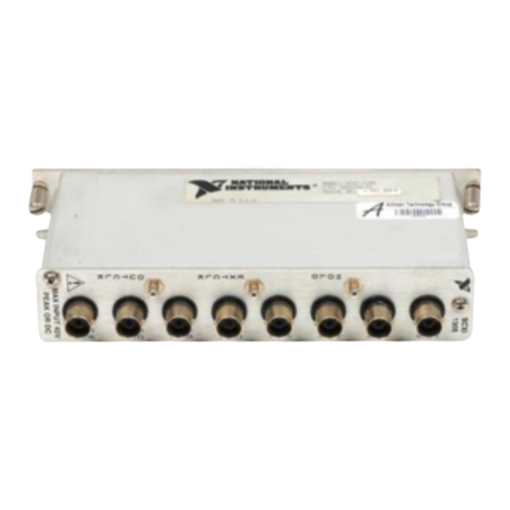
The SCXI-1305 terminal block is a shielded card with BNC and SMB
connectors that you can connect to the SCXI-1140, SCXI-1141,
SCXI-1120, SCXI-1121, or SCXI-1126 input connectors. You can
configure each SCXI-1305 channel to AC- or DC-couple a signal to an
SCXI module. Each channel can ground-reference a floating signal with a
bias resistor.
The terminal block has eight BNC and one SMB connector for easy
connection. The eight BNCs are for signal connections to the eight module
inputs. The SMB provides access to module digital signals, HOLDTRIG
for the SCXI-1140, and OUTCLK and EXTCLK for the SCXI-1141. These
signals are not active on the SCXI-1120, SCXI-1121, and SCXI-1126.
SCXI-1305 terminal block
SCXI-1305 AC/DC Coupling BNC Terminal Block Installation Guide
SCXI chassis
SCXI-1140, SCXI-1141, SCXI-1120, SCXI-1121, or SCXI-1126
module
© Copyright 1999 National Instruments Corp. All rights reserved.
BNC
OUPLING
February 1999
Advertisement

Related Manuals for National Instruments SCXI -1305


Summary of Contents for National Instruments SCXI -1305
- Page 1 SCXI chassis SCXI-1140, SCXI-1141, SCXI-1120, SCXI-1121, or SCXI-1126 module SCXI ™ is a trademark of National Instruments Corporation. Product and company names mentioned herein are trademarks or trade names of their respective companies. 322313A-01 © Copyright 1999 National Instruments Corp. All rights reserved.
- Page 2 F position connects a 100 kΩ resistor between the negative input for the channel and analog ground. This resistor supplies the necessary reference to ground for the channel. Do not use this position with the SCXI-1120, SCXI-1121, or SCXI-1126. SCXI-1305 Installation Guide © National Instruments Corporation...
- Page 3 For the SCXI-1120, SCXI-1121, and SCXI-1126, there is an effective 2 MΩ resistor instead of two 1 MΩ resistors. This 2 MΩ resistor is referenced to the negative input of the SCXI-1120, SCXI-1121, and SCXI-1126 instead of ground to maintain the SCXI-1120, SCXI-1121, and SCXI-1126 isolation. © National Instruments Corporation SCXI-1305 Installation Guide...
-
Page 4: Connecting Signals
(S4, S5, and S6) corresponds to input channel 1, and so on. The bottom set of switches (S22, S23, and S24) corresponds to input channel 7. Refer to Figure 2 for the switch locations. SCXI-1305 Installation Guide © National Instruments Corporation... - Page 5 Figure 1 shows the SCXI-1305 terminal block parts locator diagram. Back View Front View 1 Mating Connector 2 Thumbscrew 3 Top Cover Screws 4 Top Cover Figure 1. SCXI-1305 Parts Locator Diagram © National Instruments Corporation SCXI-1305 Installation Guide...
- Page 6 Signal names printed in black (the first name in the pair) are for the SCXI-1120, SCXI-1126, SCXI-1140, and SCXI-1141. Signal names printed in blue (the second name in the pair) are for the SCXI-1121. SCXI-1305 Installation Guide © National Instruments Corporation...
-
Page 7: Installing The Terminal Block
1 µF, (open) G 10%, (closed) F 10 kΩ, Ties to analog ground on the SCXI-1140 and SCXI-1141. On the SCXI-1120, SCXI-1121, and SCXI-1126, it is left floating. Figure 3. SCXI-1305 Circuit Diagram © National Instruments Corporation SCXI-1305 Installation Guide...
Need help?
Do you have a question about the SCXI -1305 and is the answer not in the manual?
Questions and answers