
Subscribe to Our Youtube Channel
Related Manuals for schmersal AZ201ST2-T-1P2P


Summary of Contents for schmersal AZ201ST2-T-1P2P
-
Page 1: Table Of Contents
INSTRUCTIONS FOR OPERATION AND ASSEMBLY Safety switch with separate actuator AZ201ST2-T-1P2P Table of Contents 1 About this document 1.1 Function 1.2 Target group of the operating instructions: authorised qualified personnel 1.3 Explanation of the symbols used 1.4 Appropriate use 1.5 General safety instructions 1.6 Warning about misuse... -
Page 2: Target Group Of The Operating Instructions: Authorised Qualified Personnel
The user must observe the safety instructions in this operating instructions manual, the country specific installation standards as well as all prevailing safety regulations and accident prevention rules. Further technical information can be found in the Schmersal catalogues or in the online catalogue on the Internet: products.schmersal.com. -
Page 3: Warning About Misuse
There are no residual risks, provided that the safety instructions as well as the instructions regarding mounting, commissioning, operation and maintenance are observed. 1.6 Warning about misuse In case of inadequate or improper use or manipulations of the component, personal hazards or damage to machinery or plant components cannot be excluded. -
Page 4: Special Versions
Only if the information described in this operating instructions manual are followed correctly, the safety function and therefore the compliance with the Machinery Directive is maintained. 2.2 Special versions For special versions, which are not listed in the ordering code, these specifications apply accordingly, provided that they correspond to the standard version. - Page 5 Standards EN ISO 13849-1 EN ISO 14119 EN IEC 60947-5-3 EN IEC 61508 Coding Universal coding Coding level according to EN ISO 14119 Working principle RFID, 125 kHz Transmitter output RFID, maximum -6 dB/m Housing material Glass-fibre, reinforced thermoplastic Duration of risk, maximum 200 ms Reaction time, switching off safety outputs via actuator, maximum 100 ms...
- Page 6 Tightening torque of the fastening screws for the housing cover, 0.7 Nm minimum Tightening torque of the fastening screws for the housing cover, 1 Nm maximum Note Torx T10 Mechanical data - Switching distances according EN IEC 60947-5-3 Assured switching distance "ON" S 4 mm Assured switching distance "OFF"...
- Page 7 Rated insulation voltage U 32 VDC Rated impulse withstand voltage U 0.8 kV Overvoltage category Degree of pollution Electrical data Operating voltage 24 VDC -15 % / +10 % No-load supply current I , typical 50 mA Rated operating voltage 24 VDC Operating current 700 mA...
- Page 8 This device complies with the nerve stimulation limits (ISED SPR-002) when operated at a minimum distance of 100 mm. Changes or modifications not expressly approved by K.A. Schmersal GmbH & Co. KG could void the user's authority to operate the equipment.
-
Page 9: Mounting
This device complies with the nerve stimulation limits (ISED CNR-102) when operated at a minimum distance of 100 In the event of changes or modifications that have not been expressly approved by K.A. Schmersal GmbH & Co. KG, the user's authorisation to use the device may become ineffective. -
Page 10: Dimensions
Mounting of the actuators Refer to the mounting instructions manual for the corresponding actuator. The actuator must be permanently fitted to the safety guards and protected against displacement by suitable measures (tamperproof screws, gluing, drilling of the screw heads). 3.2 Dimensions All measurements in mm. -
Page 11: Electrical Connection
Legend B: Active RFID area Metal parts and magnetic fields in the lateral RFID area of the safety switchgear and the actuator can influence the switching distance or lead to malfunctions. 4 Electrical connection 4.1 General information for electrical connection The electrical connection may only be carried out by authorised personnel in a de-energised condition. -
Page 12: Requirements For The Connected Safety-Monitoring Module
1 ms. The safety-monitoring module does not need to have a cross-wire short monitoring function, if necessary, the cross- wire short monitoring function must be disabled. Information for the selection of suitable safety-monitoring modules can be found in the Schmersal catalogues or in the online catalogue on the Internet: products.schmersal.com 4.4 Serial diagnostic -SD... -
Page 13: Wiring Examples For Series-Wiring
Function safety switchgear Configuration Colour codes of Poss. colour configuration of the the Schmersal code of other of the removable connector commercially connector ST2, terminal blocks plugs to DIN available M12, 8-pole 47100 connector plugs With with serial according to... - Page 14 The application examples shown are suggestions. They however do not release the user from carefully checking whether the switchgear and its set-up are suitable for the individual application. The application examples shown are suggestions. Wiring example 1: Series wiring AZ201 with conventional diagnostic output. In the series wiring, the 24V-X1-X2 bridge must be removed from all components up to the last component.
-
Page 15: Actuator Teaching / Actuator Detection
Y1 and Y2 = Safety outputs → Safety monitoring module SD-IN → Gateway → Field bus 5 Actuator teaching / actuator detection Safety switches with standard coding are ready to use upon delivery. Individually coded safety switches and actuators will require the following "teach-in" procedure: 1. -
Page 16: Diagnostic-Leds
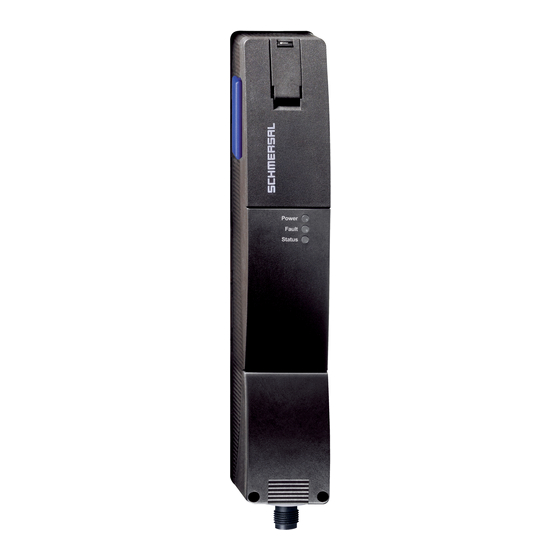
The opening of the safety guard causes the safety outputs to be disabled within the risk time. 6.2 Diagnostic-LEDs The safety switchgear signals the operational state as well as errors through three coloured LEDs installed on the front side of the device. green (Power) Supply voltage on yellow (Status) - Page 17 Table 1: Diagnostic information of the safety switchgear System condition Safety outputs Diagnostic output Y1, Y2 -1P2P green yellow Door open Door closed, actuator not inserted Door closed, 24 V 24 V actuator inserted Error warning Flashes 24 V actuator inserted, shutdown approaching Error...
-
Page 18: Safety Switch With Serial Diagnostic Function Sd
In this way, the diagnostic signals can be evaluated by means of a PLC. The necessary software for the integration of the SD-Gateway is available for download at products.schmersal.com. The response data and the diagnostic data are automatically and permanently written in an input byte of the PLC for each safety switch in the series-wired chain. -
Page 19: Set-Up And Maintenance
Table 3: I/O data and diagnostic data (The described condition is reached, when Bit = 1) Bit n° Request byte Response byte Diagnostic error Diagnostic error warning Bit 0: Safety output activated Error output Y1 Error output Y1 Bit 1: Actuator detected Error output Y2 Error output Y2... -
Page 20: Disposal
8.2 Disposal £ The safety switchgear must be disposed of in an appropriate manner in accordance with the national prescriptions and legislations. 9 Appendix – Special versions Special version -2965-1 Connecting cables with coupling (female) IP67, M23, 12 pole - 12 x 0.75 mm² Cable length Ordering code 5.0 m... - Page 21 Connecting cables with coupling (female) IP67, M23, 8+1 pole - 9 x 0.75 mm² Cable length Ordering code 5.0 m 101209959 10.0 m 101209958 15.0 m 103001384 Connecting cables with coupling (female) IP67, M12, 8 pole - 8 x 0.25 mm² Cable length Ordering code 2.5 m...
- Page 22 10.0 m 103007359 22-22 Schmersal Ltd., Sparrowhawk Close, WR14 1GL Malvern The details and data referred to have been carefully checked. Images may diverge from original. Further technical data can be found in the manual. Technical amendments and errors possible.
Need help?
Do you have a question about the AZ201ST2-T-1P2P and is the answer not in the manual?
Questions and answers