
Subscribe to Our Youtube Channel
Related Manuals for 4B Digimatic DML4W


Summary of Contents for 4B Digimatic DML4W
- Page 1 Digimatic™ RADIO FREQUENCY (RF) CAPACITANCE POINT LEVEL INDICATOR INSTALLATION INSTRUCTIONS OPERATION MANUAL Part No DML4W www.go4b.com...
-
Page 3: Table Of Contents
TABLE OF CONTENTS CUSTOMER SAFETY RESPONSIBILITIES Page 4 - 5 PRODUCT OVERVIEW Page 6 SPECIFICATIONS Page 6 DIMENSIONS Page 7 INSTALLATION Page 8 STANDARD WIRING DIAGRAM Page 9 SENSOR OPERATION Page 10 - 11 SENSOR CALIBRATION Page 12 - 13 POWER SHIELD OVERVIEW Page 14 TESTING AND COMMISSIONING... -
Page 4: Customer Safety Responsibilities
The proper installation and maintenance of all our products is the responsibility of the user unless you have asked 4B to perform these tasks. B. All installation and wiring must be in accordance with Local and National Electrical Codes and other standards applicable to your industry. - Page 5 If you have questions or comments about the operation of your unit or require the unit to be serviced please contact the 4B location who supplied the product or call us via our 24-hour hotline number in the USA (309-698-5611). Please have available product part numbers, serial numbers, and approximate date of installation.
-
Page 6: Product Overview
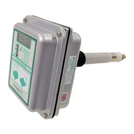
PRODUCT OVERVIEW The DIGIMATIC is a fi xed point Level Controller incorporating a microcomputer which is used to automatically calibrate the probe to suit the material being detected. Full manual override facilities are included. The DIGIMATIC employs a power shield to minimise the effect of material adhering to the probe making it ideal for detecting most materials including sticky or viscous types. -
Page 7: Dimensions
DIMENSIONS ALL DIMENSIONS IN MM PAGE 7... -
Page 8: Installation
“Low” for low level probes. Intermediate probe settings depend upon individual requirements. WARNING Proper spacing of the power shield is vital for correct operation. For questions regarding proper spacing of the power shield to the vessel wall, contact 4B. PAGE 8... -
Page 9: Standard Wiring Diagram
STANDARD WIRING DIAGRAM All wiring must be In accordance with local and national electrical codes and should be undertaken by an experienced and qualified electrician. A thread locking compound is already applied to the probe fixing stud of the DIGIMATIC. This will prevent the probe rod from vibrating loose. Once fitted, the compound is fully hardened after 20 minutes. -
Page 10: Sensor Operation
SENSOR OPERATION Image D FAIL SAFE SETTING - The “High/Low” switch (D - Image D), sets the fail safe mode. In the “High” position, the relay is energized without material present. In the “Low” position, the relay is energized with material present. Normally, the “High”... - Page 11 CAL MODE (AUTO/MAN SWITCH SET TO AUTO) - In this mode, pressing and holding the “Probe Covered / Raise” button (E - Image D) with the probe covered, will cause the unit to measure and display the covered value, and recalibrate the relay operating point if necessary.
-
Page 12: Sensor Calibration
SENSOR CALIBRATION The Digimatic can be calibrated automatically, manually or by a combination of the two methods. Usually, automatic calibration is the simplest method, particularly when the vessel can be filled to cover the probe. Manual calibration is useful when a number of probes in similar applications need to be set. Once the correct calibration has been determined and noted, on one system, the remainder can be set to the same setting. - Page 13 13. The timer can be altered to a longer or shorter delay by repeating the entire procedure from steps 10 to 12. NOTE For questions regarding non-standard Digimatic probe lengths or diameters, contact 4B. PAGE 13...
-
Page 14: Power Shield Overview
POWER SHIELD OVERVIEW The Digimatic detects material by radiating a high frequency (RF) signal from the probe. The advanced electronics of the Digimatic use this signal to measure the capacitance inside the vessel with respect to ground and thus indicate when material has reached the Digimatic probe. The power shield creates a barrier and enables the unit to ignore a certain amount of material built up on the probe, helping to prevent false readings. -
Page 15: Testing And Commissioning
3. Introduce material to the Digimatic. If calibrated correctly, the Digimatic will activate when material has been detected. Machinery shut down will depend on your specific monitoring setup. 4B recommends an instant shutdown when maximum fill level or a plug condition has been detected. -
Page 16: Parts And Accessories
PARTS & ACCESSORIES STAINLESS STEEL PROBES/WIRE ATSP10 ATSP11 ATSP12 ATSP13 ATWP11 The Digimatic is available with 303 solid stainless steel probes. For applications up to 10 meter 33 feet long (maximum), 303 stainless steel wire is used to extend the probe length. -
Page 17: Product Warranty
AS 4B TO THE ORIGINAL PURCHASER AGAINST DEFECTS IN WORKMANSHIP OR MATERIALS UNDER NORMAL USE FOR ONE (1) YEAR AFTER DATE OF PURCHASE FROM 4B. ANY PRODUCT DETERMINED BY 4B AT ITS SOLE DISCRETION TO BE DEFECTIVE IN MATERIAL OR WORKMANSHIP AND RETURNED TO A 4B BRANCH... - Page 18 NOTES PAGE 18...
- Page 19 NOTES PAGE 19...
- Page 20 Wujin High & New TDZ, Australia Samutprakarn 10540 Changzhou, Jiangsu, PRC Tel: +61 (0)7 3216 9365 Thailand Tel: +86-519-88556006 Email: 4b-australia@go4b.com Tel: +66 (0) 2 173-4339 Email: 4b-china@go4b.com Email: 4b-asiapacific@go4b.com www.go4b.com Copyright © 2018 4B Group - All Rights Reserved REV031423 M2605(B)
Need help?
Do you have a question about the Digimatic DML4W and is the answer not in the manual?
Questions and answers