
Related Manuals for Peak Gas Generation i-FlowLab Prime 7 1 Series


Summary of Contents for Peak Gas Generation i-FlowLab Prime 7 1 Series
- Page 1 i-Flow 7000 Series N2 Generators User Manual Copyright © Peak Scientific Instruments Ltd 2024 — i-Flow 7000 Series User Manual Rev 6 RSID 4707 PN UM-0029 EN —10/01/2024...
- Page 2 Register Product to Operate To begin operation you will need to register your generator. You can do so by visiting www.peakscientific.com/activate or by downloading the Peak Genius App. Registering will activate your 2 year warranty* - covering every single component in your generator. ...
-
Page 3: Table Of Contents
Contents Change History Introduction Technical Description Basic Concept i-Flow 7000 Series Model Number Breakdown Warranties and Liabilities Warranty & Liability Coverage Safety Notices Symbols Safety Notice to Users EU Declaration of Conformity UKCA Declaration of Conformity CSA Compliance Statement WEEE Compliance Statement European Union (EU) and United Kingdom (UK) Class A Compliance statement FCC Class A Compliance Statement Industry Canada Class A emission compliance statement... -
Page 4: Change History
Change History Comment Name Date Flow Updates L. Couttie 05/09/2023 Declarations Update L. Couttie 03/10/2023 Text Update L. Couttie 09/11/2023 Valve + weight edits C.Denholm 10/01/2023 How to use this Manual This manual is intended for end users and has been written as a reference document where you can skip to the relevant information. -
Page 5: Introduction
Peak Gas Generation or the Peak Partner from which you purchased your Generator. Peak Gas Generation is a Trading Name of Peak Scientific Instruments Ltd. All Peak Gas Generation products are manufactured by Peak Scientific Instruments Ltd. -
Page 6: Technical Description
Technical Description Basic Concept i-Flow N2 Mini & N2 Prime are a range of modular nitrogen gas generators, that operate based on the latest Pressure Swing Adsorption (PSA) technology, utilising a Carbon Molecular Sieve (CMS) to extract nitrogen from air, at the specified flow, purity & pressure. -
Page 7: I-Flow 7000 Series Model Number Breakdown
i-Flow N2 Prime Base unit with Base unit with minimum single maximum 10 bank of dual banks of dual CMS columns. CMS columns The front end cabinet, control system and valves are consistent across the entire range. To increase the outlet capacity, as you go up the range of generators, additional banks of CMS columns can be added. -
Page 8: Warranties And Liabilities
Warranties and Liabilities Warranty & Liability Coverage Peak warrants that, subject to the provisions in this statement, purchased Peak generators, whether purchased directly from Peak or indirectly via an approved, certified and trained distributor or partner (referred to hereafter as a “Peak Partner”) will comply in all material respects with any specifications referred to in your customer order confirmation and, subject to installation and operational guidelines being followed as described in applicable product manuals, shall be free from any defects in quality of materials or workmanship for a period of one year from the date of installation, provided this takes... - Page 9 8. Peak shall not be liable in respect of any claim made for costs, damages, losses or expenses (whether consequential, direct, indirect or otherwise) or in any respect howsoever arising including, but not limited to, liability from accident or negligence (other than pursuant to clause 5) that may be suffered by you or any third party.
-
Page 10: Safety Notices
Safety Notices Peak Gas Generation cannot anticipate every possible circumstance which may represent a potential hazard. The warnings detailed within this manual detail the most known potential hazards, but by definition cannot be all inclusive. If the user employs an operating procedure, item of equipment or a method of working which is not specifically recommended by Peak, the user must ensure that the equipment will not be damaged or become hazardous to persons or property. -
Page 11: Eu Declaration Of Conformity
EU Declaration of Conformity Peak Scientific Instruments Ltd. Fountain Crescent, Inchinnan, Renfrewshire, PA4 9RE Hereby declare that, this declaration of conformity is issued under the sole responsibility of the manufacturer. Equipment Type: Nitrogen Generator Model Designator: i-Flow 7000 & 9000 Series PED Module B Certificate No : CE 744518 PED Module D Certificate No : CE 608103 Pressure assembly consisting of the following key parts :... -
Page 12: Ukca Declaration Of Conformity
UKCA Declaration of Conformity Peak Scientific Instruments Ltd. Fountain Crescent, Inchinnan, Renfrewshire, PA4 9RE Hereby declare that, this declaration of conformity is issued under the sole responsibility of the manufacturer. Equipment Type: Nitrogen Generator Model Designator: i-Flow 7000 & 9000 Series PED Module B Certificate No : UKCA 753392 PED Module D Certificate No : UKCA 753395 Pressure assembly consisting of the following key parts :... -
Page 13: Csa Compliance Statement
CSA Compliance Statement CSA Group (Canadian Standards Authority) is a Nationally Recognised Testing Laboratory (NRTL), headquartered in Toronto Canada. They are authorised to evaluate product to both their own and Underwriters Laboratory (UL) standards and certify the product to be in compliance to the relevant standards. Peak products are certified to the current in force revision of the following standards in order to cover both Canadian and United States requirements for “Safety Requirements for Electrical Equipment for Measurement, Control and Laboratory use,... -
Page 14: Weee Compliance Statement
WEEE Compliance Statement The Waste Electrical and Electronic Equipment (WEEE) Regulations SI 2013 No 3113 and or the Waste Electrical and Electronic Equipment (WEEE) Directive 2012/19/EU apply to all electrical and electronic equipment placed on the market in the UK and EU covered by the scope of regulations which can be found in the Government Guidance Notes (PDF) produced by the Department for Business Innovation and skills for the UK and here for Europe. -
Page 15: European Union (Eu) And United Kingdom (Uk) Class A Compliance Statement
EMC Class A Compliance Statements European Union (EU) and United Kingdom (UK) Class A Compliance statement This is a Class A product. In a domestic environment this product may cause radio interference in which case the user may be required to take adequate measures. FCC Class A Compliance Statement This equipment has been tested and found to comply with the limits for a Class A digital device, pursuant to part 15 of the FCC Rules. -
Page 16: Technical Specification
Depending on your specific application, the pressure and flow required from the compressed air supply to the generator will vary. For your specific requirements please refer to your quotation documents, or contact Peak Gas Generation for further information. However all installations must meet the following conditions: Minimum Air Quality IS0 8573-1:2010 class 2.4.1... - Page 17 General i-Flow Mini 1 Bank 2 Banks 3 Banks 4 Banks Width mm(in) 418 (16.5) Height mm(in) 853 (33.6) Depth mm(in) 830 (32.7) 992 (39.1) 1154 (45.4) 1316 (51.8) Weight kg(lbs) 96 ( 211) 132 (291) 178 (392) 214 (471) Shipping weight kg(lbs) 144 (317) 184 (405)
-
Page 18: Unpacking
Check ‘SHOCKWATCH’ and ‘TIP-N-TELL’ labels for signs of rough handling prior to unpacking. Any damage should be reported immediately to the carrier and Peak Gas Generation or the Peak Partner from where the unit was purchased. Page 18... -
Page 19: Installation
Installation It is the user/installer’s responsibility to ensure that the generator is located and protected against any external influences such as vibration, shock, wind, snow loading, earthquake or fire. The installation should conform to all local regulations and should be leak tight and completed by technically competent personnel. -
Page 20: Generator Overview
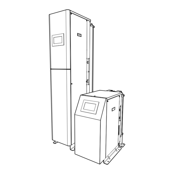
Generator Overview i-Flow Mini General Dimensions 418 mm / 16.4” 830 mm / 32.7” 1316 mm / 51.8” Note: Each additional bank assembly = 162mm / 6.4” The Generator must always be placed on a level surface. Failure to do so will affect the stability of the Generator. -
Page 21: Generator Overview
Generator Overview i-Flow Prime General Dimensions 418 mm / 16.4” 730 mm / 28.7” 2188 mm / 86.1” Note: Each additional bank assembly = 162mm / 6.4” The Generator must always be placed on a level surface. Failure to do so will affect the stability of the Generator. -
Page 22: Inlet / Outlet Connections
Inlet / Outlet Connections The i-Flow 7000 Series generators can be piped (air inlet and gas outlet) from either side to suit site/ location. The unit will be supplied with two blanking plugs which can be installed in either the left or right hand ports to allow the opposite side to be used. i-Flow Mini i-Flow Prime Compressed... -
Page 23: Recommended Piping Layout
Recommended Piping Layout To allow for proper operation and commissioning of the generator it is important to include isolation and vent valves at the locations displayed below, the i-Flow 7000 Series generators can be piped (air inlet and gas outlet) from either side to suit site/ location. -
Page 24: Compressed Air Quality
Should you require any further assistance or support please do not hesitate to contact Peak Gas Generation or the Peak Partner from which you purchased your Generator. A full installation and commissioning service can be provided through the Peak Global Service network. -
Page 25: Electrical Connection
Electrical Connection Connect the Generator to a single-phase AC voltage supply using the power cord provided. The generator is fitted with an internal transformer that can accept any supply from 100 to 240 volts AC. If the appropriate power cord is not supplied; a new plug, rated to at least 5 amps, can be fitted by a qualified electrician. -
Page 26: Product Registration
Product Registration Before the generator will start up for the first time the user must enter a unique 4-digit PIN code. To receive your generator’s unique PIN code, please register on the Peak website www. peakscientific.com/activate or download the Peak mobile app from the Google Play Store or Apple App Store. -
Page 27: Home Screen
Home Screen This is the Main Home page screen at first startup of the system. Error Icon in the top right of the screen is Normal, as pressure will be low and O2 content will be high. Touching the red triangle icon, will take you to the error page. -
Page 28: Settings Screen
Settings Screen This is the Settings Screen where displayed language can be selected. Service Screen This is the Service Lock Screen – only trained and authorised engineers will have the ability to enter a PIN code and access generator settings and param- eters. -
Page 29: Screen Warning Icons
Screen Warning Icons The Red warning triangle in the top right corner of the screen, indicates a fault condition is active on the system. Pressing the icon will take you to the Error page which will include a full description of the fault. -
Page 30: Commissioning & Safe Start-Up Sequence
Commissioning & Safe Start-Up Sequence Note: The side panels of the generator should not be removed during operation unless you have received training and are technically competent to manage the potential risks present. Located inside the cabinet are the vent silencers and safety relief valve, which periodically release gas at WARNING pressure and could cause injury. - Page 31 Once the desired tank pressure has been achieved, the system will automatically exit the “Shortcycle” mode and begin “Normal Operation”. The system will continue to produce Gas until the Standby pressure is reached, at which point the generator will enter the “Standby” mode. Once in “Standby”...
-
Page 32: Normal Operation
Normal Operation i-Flow 7000 series gas generators are designed specifically to minimize operator involvement. As long as the system is installed as described in earlier sections and is serviced in accordance with the specified maintenance recommendations (see Service Requirements), then it should simply be a matter of turning the Generator on. Note: the generator will only produce nitrogen gas based on demand, so should typically be left in a powered state with live compressed air supply. -
Page 33: Safe Isolation Process
Safe Isolation Process With reference to the diagram in the Recommended Piping Layout section. To shut the system down, first close the Tank/Application isolation Valve (7) and the Generator outlet isolation Valve (5), this will isolate and preserve the gas within the Nitrogen receiver/storage/buffer tank. -
Page 34: Service Requirements
Service Requirements Due to the simplicity of the design and the small number of moving parts the i-Flow N2 Nitrogen Generators will have a long and trouble free life. However as with all technical equipment it should be regularly inspected and serviced as below. Service Schedule Purchase Interval Unit... -
Page 35: Service Indication
Service Indication The generator will notify the user of the service interval for the filter elements. The generator has the following Service Indication Stages:- Stage 1 When less than 30 days are remaining on the service counter the Service Due icon will show in the top right corner of the Home Screen. -
Page 36: Peak Protected
Peak Protected With Peak Gas Generation you invest in not only a product but peace of mind. With a network of certified Peak engineers stationed throughout the globe, Peak’s rapid response team are never far away and our commitment is to keep your generator running day in, day out, protecting your productivity. -
Page 37: Cleaning
Generator or material contained within it. If there is any doubt about the compatibility of decontamination or cleaning agents please contact your Peak Gas Generation representative. Cleaning should only be undertaken with the power switched off and the power cord removed from the rear of the generator. -
Page 38: Error Messages
Error Messages In the event of a fault condition on the system the RED warning triangle will be displayed in the top right corner of the Home Screen, pressing the Icon will take you to the Error Page. Please note that upon start-up, the RED warning triangle is normal (refer to P26 of the user manual) If no faults are currently active the Error Page will be blank, possible Error Messages are: When less than 30 days remaining on service counter, this... -
Page 39: Troubleshooting
Troubleshooting Problem Possible Solution • Ensure power cable is plugged into the generator and that the socket is turned on • Check the fuse in the power cable plug (if The generator will not switch on and the fitted) power switch does not illuminate. •... - Page 40 Peak Gas Generation gas generators define the benchmark in reliability, convenience and performance in facilities around the world, and come backed by a 12 month on-site warranty. Beyond this period how- ever you can ensure that your investment continues to be [Protected] by our comprehensive generator care cover.
Need help?
Do you have a question about the i-FlowLab Prime 7 1 Series and is the answer not in the manual?
Questions and answers