
Related Manuals for Peak Gas Generation i-Flow 6000 Series


Summary of Contents for Peak Gas Generation i-Flow 6000 Series
- Page 1 6000 Series User Manual Copyright © Peak Scientific Instruments Ltd 2021 — i-Flow 6000 Series User Manual Rev 14 RSID 175 PN UM00018 EN (Rollback) —28/10/2021...
-
Page 2: Table Of Contents
Contents Change History How to use this Manual Introduction Technical Description Basic Concept i-Flow 6000 Model Number Breakdown Warranties and Liabilities Warranty & Liability Coverage Safety Notices EU Declaration of Conformity Environmental Declaration Technical Specification Unpacking Installation Generator Environment Generator General Dimensions Inlet / Outlet Connections Unit Controls... -
Page 3: Change History
Users can refer to the contents page to find the relevant information. Please review each of the following sections carefully. Thank you for selecting Peak Gas Generation to meet your gas generation needs, and should you require any further assistance or support please do not hesitate to contact Peak Gas Generation or the Peak Partner from which you purchased your generator. -
Page 4: Introduction
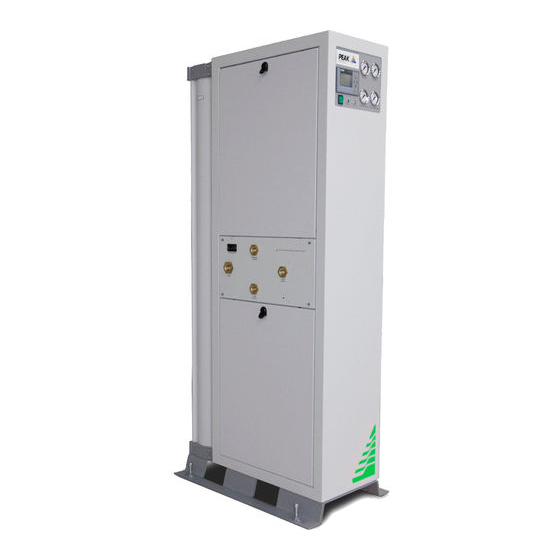
Introduction The Peak Gas Generation i-Flow 6000 Generator is designed to cater for a wide variety of industrial and scientific applications. Your generator will have been carefully selected to meet your specific pressure, flow, and purity requirements, if you have any questions regarding the sizing of your system please do not hesitate to contact Peak Gas Generation or the Peak Partner from which you purchased your Generator. -
Page 5: Technical Description
Technical Description Basic Concept The i-Flow is a modular range of Carbon Molecular Sieve (CMS) nitrogen gas generators, that operate based on Pressure Swing Adsorption (PSA) technology. Essentially this requires two separate columns or “beds” of granular carbon pellets. The unit requires a compressed air supply to operate, ultimately works on very similar principles to many standard air filtration / drying products. -
Page 6: I-Flow 6000 Model Number Breakdown
i-Flow 6000 Model Number Breakdown Model Numbering Peak Range No. of Banks Customer Option 1 Bank None - Basic Unit 2 Banks i-Flow - % Oxygen Analyser 3 Banks i-Flow - PPM Oxygen Analyser 4 Banks Inlet/Outlet Filter - No Oxygen Analyser 5 Banks Inlet/Outlet Filter - % Oxygen Analyser 6 Banks... -
Page 7: Warranties And Liabilities
(inclusive of warranty period specified in clause 1) from date of installation, provided this takes place within 3 months of factory dispatch. 3. Where the purchased generator is from the i-Flow 6000 series, Peak further warrants that, subject to installation and operational guidelines being followed as described in applicable product manuals,... - Page 8 8. Peak shall not be liable in respect of any claim made for costs, damages, losses or expenses (whether consequential, direct, indirect or otherwise) or in any respect howsoever arising including, but not limited to, liability from accident or negligence (other than pursuant to clause 5) that may be suffered by you or any third party.
-
Page 9: Safety Notices
Safety Notices Peak Scientific Instruments cannot anticipate every possible circumstance which may represent a potential hazard. The warnings detailed within this manual detail the most known potential hazards, but by definition cannot be all inclusive. If the user employs an operating procedure, item of equipment or a method of working which is not specifically recommended by Peak Scientific, the user must ensure that the equipment will not be damaged or become hazardous to persons or property. -
Page 10: Eu Declaration Of Conformity
Equipment: Pressure Swing Adsorption Gas Generator Models: i-Flow 6000 Series & i-Flow O2 8000 Series PED Module B Certifi cate No : CE 608102 PED Module D Certifi cate No : CE 608103 Pressure assembly consisting of the following key parts : PED Hazard Cat. - Page 11 Equipment: Pressure Swing Adsorption Gas Generator Models: i-Flow 6000 Series & i-Flow O2 8000 Series PED Module B Certificate No : UKCA 753392 PED Module D Certificate No : UKCA 753395 Pressure assembly consisting of the following key parts : PED Hazard Cat.
- Page 12 WEEE Compliance Statement The Waste Electrical and Electronic Equipment (WEEE) Regulations SI 2013 No 3113 and or the Waste Electrical and Electronic Equipment (WEEE) Directive 2012/19/EU apply to all electrical and electronic equipment placed on the market in the UK and EU covered by the scope of regulations which can be found in the Government Guidance Notes (PDF) produced by the Department for Business Innovation and skills for the UK and here for Europe.
-
Page 13: Technical Specification
Depending on your specific application, the pressure and flow required from the compressed air supply to the generator will vary. For your specific requirements please refer to your quotation documents, or contact Peak Gas Generation for further information. However all installations must meet the following conditions: Minimum Air Quality IS0 8573-1:2010 class 1.4.1 or 1.2.1†... - Page 14 General Model 601* 602* 603* 604* 605* Width mm(in) 500 (19.68) Height mm(in) 1738 (68.42) Depth mm(in) 760(29.92) 920(36.22) 1080(42.52) 1240(48.82) 1400(55.12) Weight kg(lbs) 197(433) 282(620) 367(807) 452(994) 537(1181) Shipping weight kg(lbs) 277(609) 364(801) 451(992) 538(1184) 625(1375) Noise level 59 dBA @ 1m Model 606* 607*...
-
Page 15: Unpacking
Check ‘SHOCKWATCH’ and ‘TIP-N-TELL’ labels for signs of rough handling prior to unpacking. Any damage should be reported immediately to the carrier and Peak Gas Generation or the Peak Partner from where the unit was purchased. Page 15... -
Page 16: Installation
Installation It is the user/installer’s responsibility to ensure that the generator is located and protected against any external influences such as vibration, shock, wind, snow loading, earthquake or fire. The installation should conform to all local regulations and should be leak tight and WARNING completed by technically competent personnel. -
Page 17: Generator
Generator General Dimensions 500 mm / 19.7” 760 mm / 29.9” 2200 mm / 86.6” Note: Each additional bank assembly = 160mm / 6.3” The Generator must always be placed on a level surface. Failure to do so will affect the stability of the Generator. WARNING Page 17... -
Page 18: Inlet / Outlet Connections
Inlet / Outlet Connections All of the Generator output ports are located on the output panel on the Left hand side of the Generator. See below for recommended piping layout. Power Inlet Nitrogen Output ¾” BSP Air Inlet 1” BSP Tank Supply ¾”... -
Page 19: Compressed Air Quality
• Water Separator • Pre-filter • Active Carbon Filter • Line Air Regulator • Desiccant Air Dryer • Dust Filter • Active Carbon Tower • Dust Filter • i-Flow 6000 Series Nitrogen Generator • Nitrogen Process Gas Tank Page 19... - Page 20 Should you require any further assistance or support please do not hesitate to contact Peak Gas Generation or the Peak Partner from which you purchased your Generator. A full installation and commissioning service can be provided through the Peak Global Service network.
-
Page 21: Electrical Connection
Electrical Connection Connect the Generator to a single-phase AC voltage supply using the power cord provided. The generator is fitted with an internal transformer that can accept any supply from 100 to 240 volts AC. If the appropriate power cord is not supplied; a new plug, rated to at least 5 amps, can be fitted by a qualified electrician. -
Page 22: Recommended Piping Layout
Recommended Piping Layout To allow proper operation and commissioning of the generator it is important to include bypass valves at the generator inlet / nitrogen outlet of the system. It is also recommended that a non-return valve be fitted on the exit of the system to prevent downstream pressure from returning to the system and damaging the generator. -
Page 23: Commissioning & Safe Start-Up Sequence
If unable to achieve specification contact Peak Gas Generation for further assistance. After this time the outlet bypass valve (3) can be closed, and the delivery valve (4) to the customer application should be slowly opened to pressurize the line. -
Page 24: Normal Operation
Normal Operation The i-Flow 6000 Gas Generator is designed specifically to minimize operator involvement. As long as the system is installed as described in earlier sections and is serviced in accordance with the specified maintenance recommendations (see Service Requirements), then it should simply be a matter of turning the Generator on. Note: the generator will only produce nitrogen gas based on demand, so should typically be left in a powered state, live compressed air supply. -
Page 25: Service Requirements
Service Requirements Service Schedule Quantity. Purchase Interval Component Part No. 601*-605* 606*-610* Vent Silencer Element 02-5710 12 months Pneumatic Valve Exhaust Silencer 02-1016 N2 Supply NRV 02-5620 O2 Analyser %* 04-4571 48 months O2 Analyser PPM* 04-4572 *Analyzer service is dependent on selected model. Page 25... -
Page 26: Peak Protected
Peak Protected With Peak Gas Generation you invest in not only a product but peace of mind. With a network of certified Peak engineers stationed throughout the globe, Peak’s rapid response team are never far away and our commitment is to keep your generator running day in, day out, protecting your productivity. -
Page 27: Cleaning
Generator or material contained within it. If there is any doubt about the compatibility of decontamination or cleaning agents please contact your Peak Gas Generation representative. Cleaning should only be undertaken with the power switched off and the power cord removed from the rear of the generator. - Page 28 Not all warranties are alike and Peak Gas Generation stand out against other gas suppliers as we offer a comprehensive, quick response, on-site warranty. This means that in the...
- Page 29 Tel: +44 141 812 8100 Fax: +44 141 812 8200 For further information on any of our generator products please contact contact@peakgas.com Copyright © Peak Scientific Instruments Ltd 2021 — i-Flow 6000 Series User Manual Rev 14 RSID 175 PN UM00018 EN (Rollback) —28/10/2021...