Table of Contents
Advertisement
Quick Links
UHF FM Transceiver
DJ-G46
Instruction Manual
Thank you for purchashing your new Alinco transceiver.Please read this manual
carefully before using the product to ensure full performance, and keep this
manual for future reference as it contains information on after-sales service.
In case addendum or errata sheets are included with this product,please read
those materials and keep them together with this instruction manual for future
GMRS TRANSCEIVER
reference.
GMRS license is required to operate this device.
Advertisement
Table of Contents

Subscribe to Our Youtube Channel
Related Manuals for Alinco DJ-G46


Summary of Contents for Alinco DJ-G46
- Page 1 UHF FM Transceiver DJ-G46 Instruction Manual Thank you for purchashing your new Alinco transceiver.Please read this manual carefully before using the product to ensure full performance, and keep this manual for future reference as it contains information on after-sales service.
- Page 2 Introduction Thank you very much for purchasing this excellent Alinco transceiver. Our products are ranked among the finest in the world. This radio has been manufactured with state of the art technology and it has been tested carefully at our factory. It is designed to operate to your satisfaction for many years under normal use.
- Page 3 Alinco accessories and the radio has not been disassembled by the customer. The factory has tested and made the equipment compatible to IP54 certification during engineering.
- Page 4 ■ FCC Warning Statement Any Changes or modifications not expressly approved by the party responsible for compliance could void the user’s authority to operate the equipment. This device complies with part 15 of the FCC Rules. Operation is subject to the following two conditions: (1) This device may not cause harmful interference, and (2) This device must accept any interference received, including interference that may cause undesired operation.
- Page 5 ■ Handheld Operation This device has been tested and meets the FCC/ISEDC RF exposure guidelines when used with an accessory designated for this product or when used with and accessory that contains no metal. To maintain compliance with the FCC/ISEDC’s RF exposure guidelines, hold the transmitter and antenna at least 1 inch from your face and speak in a normal voice, with the antenna pointed up and away from the face.
- Page 6 Features ■ Li-Ion battery pack and stand-charger as standard accessories ■ FM broadcasting 76-108MHz receiver built-in ■ Sub-tone (CTCSS/DCS) Encode/ Decode and DTMF/ANI Conformity Symbols Tested to comply MIL-STD-810G -Shock: Method 514.6/I,IV -Vibration: Method 516.6/I...
- Page 7 Alert Environment and condition of use Use of this product may be prohibited or illegal outside of your country. Be informed in advance when you travel. It is recommended that you check local traffic regulations regarding the use of a radio equipment while driving.
- Page 8 The manufacturer declines any responsibilities against loss of life and property due to a failure of this product when used with or as a part of a device made by third parties. Use of third party accessory may result in damage to this product. It will void our warranty for repair. Handling this product Be sure to reduce the audio output level to minimum before using an earphone or a headset.
- Page 9 Securely plug the adapter into the wall outlet. Insecure installation may result in short-circuit, electronic shock and/or fire. Do not use the adapter if the plug or socket contacts are dirty. Overheating and/or short-circuiting may result in fire, electric shock and/or damage to the product. In case of emergency In case of the following situation(s), please turn off the product, switch off the source of power, then remove or unplug the power-cord.
- Page 10 Alert Environment and condition of use Do not use the product in proximity to a TV or a radio. It may cause interference or receive interference. Do not install in a humid, dusty or insufficiently ventilated place. It may result in electric shock, fire and/or malfunction.
- Page 11 PC Programming Required DJ-G46 Utility software is required to use all the functions of this product and edit memory channels.An optional PC cable ERW-7 is necessory. Please read the instruction of software for programming. Please contact your dealer for...
-
Page 12: Table Of Contents
CONTENTS STANDARD ACCESSORIES/OPTIONAL ACCESSORIES ............. 1 Standard Accessories .........................1 BATTERY INFORMATION ........................ 2 Charging Operation ..........................2 Battery Charger Type ..............................2 Notice For Charging Battery ............................2 How To Charge The Battery Pack ..........................5 How To Store The Battery ............................6 INSTALLATION & CONNECTION ....................7 Installing / Removing The Li-Ion Battery ........................7 Installing / Removing The Belt Clip ..........................7 Accessories ................................8... - Page 13 CONTENTS Side Key[PF2](Keypad lock) ............................14 Squelch Off ................................14 Receiving ...................................15 Transmitting ................................15 Resetting ...................................15 KEY ASSIGNMENT........................... 16 AVAILABLE FUNCTIONS........................ 18 Call ....................................18 Emergency ................................18 Monitor ..................................18 Adiustment Squelch Level ............................18 Reverse ..................................18 Talk Around ................................19 Key Lock ..................................19 Tx Power Select ................................19 VOX Sensitivity Level ..............................20 VOX Delay Time ................................20...
- Page 14 CONTENTS Backlight Settiing ...............................21 Language Setting ..............................21 Color Setting ................................21 P1 KEY OPERATIONS........................22 Tone Squelch/DCS Squelch (Sub tone CTCSS/DCS) Encode/Decode Tones Synchronized Setup ......22 Scan ..................................22 P2 KEY OPERATIONS........................23 Turn On/ Off FM Radio Receiver ..........................23 Squelch Level ................................23 Tone Burst .................................23 OPTIONAL ACCESSORIES..................
-
Page 15: Standard Accessories/Optional Accessories
STANDARD ACCESSORIES/OPTIONAL ACCESSORIES Standard Accessories Belt Clip Battery AC Adaptor Battery Charger EBC-34 EDC-314 EBP-87 EDC-191T Antenna Instruction Hand Strap EA-212 Manual NOTE: Accessories may differ depending on the version you have purchased. Please contact your local dealer for details of standard accessories and the warranty-policy before purchase. Professional FM Transceiver... -
Page 16: Battery Information
5 years at the longest. Deteriorated batteries risk short- circuit causing explosion and fire. Battery Charger Type Please use Alinco's designated charger, other models may cause explosion and injury. After installing the battery, when the radio displays low battery, please charge the battery. - Page 17 BATTERY INFORMATION Caution • Risk of explosion, generation of heat or leak of chemicals inside if the battery is replaced by an incorrect type or reverse polarity. Use always the recommended types of batteries in this manual only. • Don't modify, dismantle, incinerate or immerse the battery pack in the water as this can be dangerous.
- Page 18 BATTERY INFORMATION IMPORTANT ■ Handling and storing information of batteries and battery packs. Batteries contain flammable materials. Mishandling shall cause batteries to rupture producing extreme heat, fire, deteriorate or cause damages to you and your properties. Please care about the following information.
-
Page 19: How To Charge The Battery Pack
BATTERY INFORMATION How to Charge the Battery Pack 1.Plug the AC adaptor into the AC outlet 120V, then plug the cable of AC adaptor into the DC jack, the indicator lights RED on for 1 second then turns to GREEN . 2.Slide the battery or transceiver with battery into the charger;... -
Page 20: How To Store The Battery
BATTERY INFORMATION NOTE: ▲ Trouble means battery heating, short-circuit or charger malfunction. Remove the battery pack from the charger immediately and contact to your local dealer for services. ▲ It is known that Li-Ion battery packs heat up over 400℃ by itself when kept in a temperature of over 80℃ for extended period of time. -
Page 21: Installation & Connection
INSTALLATION & CONNECTION Installing / Removing the Li-ion Battery 1.Match the three grooves of the battery pack with the corresponding guides on the back of the transceiver, then push it. 2.Press the battery and transceiver firmly together until the release latch on the top of the transceiver locks. After hearing a“click”sounds, the battery has been locked. -
Page 22: Accessories
INSTALLATION & CONNECTION Accessories Open the jack cover and insert the accessory plug into the jack,as shown. When the accessory is not used, please be sure to close the cover securely. Incorrect operation may result in water penetration to destroy the circuit boards inside. NOTE: 1. -
Page 23: Installing The Hand Strap
INSTALLATION & CONNECTION Installing the Hand Strap Attach the hand strap as shown. Professional FM Transceiver... -
Page 24: Getting Acquainted
GETTING ACQUAINTED LCD Display Following are the meaning of the icons and signs shown on the display. Some icons may not appear while operating this product due to pre-programming status by your dealer. Offset Direction Reverse Priority Scan Talk Around Narrow CTCSS Battery Capacity... -
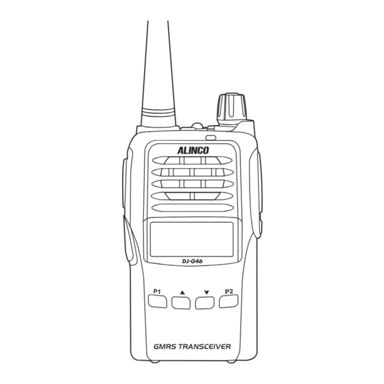
Page 25: Front Panel
Power/volume switch Lights green while receiving, lights red while transmitting, remains off in stand-by. Speaker Microphone ※Do not close the microphone hole. DJ-G46 Up/Down key P2 key Short press: FM radio Long press: Squelch Level P1 key Short press: Tone/DCS squelch... -
Page 26: Side Panel
GETTING ACQUAINTED Side Panel PTT key Accessory and PC programming port PF1 key Short press: None Long press: Lighting PF2 key Short press: Monitor Long press: Key Lock Belt Clip Battery Functions of PF1 and PF2 keys are rogrammable by using utility software. This manual explains the feature of default setting. -
Page 27: Basic Operations
BASIC OPERATIONS Power On and off Turn 【 POWER 】 / 【 VOLUME 】 dial clockwise to power on. Turn it counterclockwise to power off. Adjusting Audio output Level Press PF2 key to monitor white noise to refer to the current audio level. Turn 【... -
Page 28: Emergency Alarm Function
BASIC OPERATIONS Emergency Alarm Function While Stand-by state, press this key for 3 seconds to enable the emergency alarm function. When activated the function, the radio will sound an alarm beep and start transmitting the alarm beep. Press the same key again to turn off the alarm. -
Page 29: Receiving
BASIC OPERATIONS Receiving Select the channel that you wish to operate by trialngle keys. When a signal is received on the channel that you selected, and S-meter is displayed on the LCD, then the received signal can be heard. The RX indicator also lights while receiving. NOTE: Please be aware of the squelch level and selective-calling settings such as CTCSS and DCS as you may risk not hearing the receiving signal. -
Page 30: Key Assignment
KEY ASSIGNMENT Up to 8 of below functions can be assigned to P1/P2/PF1/PF2 keys' short-press and long press operation using the software. Please read following pages for details of functions. FUNCTION NAME CALL LCD displays DTMF data and group number (total 16 groups)of current group. Emergency Emergency alarm function. - Page 31 KEY ASSIGNMENT FUNCTION NAME CTCSS/DCS SEL Select CTCSS/DCS. Compandar This feature reduces the back-ground noise and enhances audio clarity. VOX Sensitivity When this function is on. the transmitting can be started by voice, no need to press [PTT] key. Level If transceiver returns to receive mode instantly after VOX calling, it may cause calling voice VOX Delay time missing.
-
Page 32: Available Functions
AVAILABLE FUNCTIONS To use features herein, preprogramming may be necessary. Call Under the standby conditions, press the programmed key to transmit the prestored and selected DTMF signaling. Presetting DTMF CALL is also necessary. Emergency Under the standby conditions press the programmed key to transmit the prestored emergency call. Monitor Under the standby conditions, pressing and releasing the programmed key, it beeps and enters the monitor state. -
Page 33: Talk Around
AVAILABLE FUNCTIONS Talk Around Under the standby conditions, pressing the programmed key, it beeps and activates TalkAround. In case of semi-duplex channels, it will transmit on receiving frecuency and CTCSS/DCS encode/ decode setting will be reversed. This ables the user to talk to other users without using the repeater. Press the key again, it beeps twice and Talk-around is deactivated. -
Page 34: Vox Sensitivity Level
AVAILABLE FUNCTIONS VOX Sensitivity Level Under the standby conditions, pressing the programmed key, it beeps and enters the VOX sensitivity level select state. VOX Delay Time Under the standby conditions, pressing the programmed key, it beeps and enters the vox delay time select state. -
Page 35: Scan Add And Del
AVAILABLE FUNCTIONS Scan Add and Del Under the standby conditions, pressing the programmed key, it can select to add or delete from scan group. Lighting Under the standby conditions, pressing the programmed key, it lits jacklight. Backlight Settiing Under the standby conditions, pressing the programmed key, it beeps and enters the backlight setting state. -
Page 36: P1 Key Operations
P1 KEY OPERATIONS Following functions are assigned to P1 key as default. Tone Squelch / DCS Squelch (Sub tone CTCSS / DCS) Encode/Decode Tones Synchronized Setup Short press 【 P1 】 key, 【 ▲ 】and【 ▼ 】 to choose the desired CTCSS / DCS encode tone. Available CTCSS tones: 67Hz- 254.1Hz, 50 tones in total, Deafault is OFF. -
Page 37: P2 Key Operations
P2 KEY OPERATIONS Following functions are assigned to P2 key as default. Turn On/ Off FM Radio Receiver Short pressing 【 P2 】 key, FM Radio is enabled. LCD displays 'FM' and starts receiving FM broadcasting frequency. Repeat the operations to turn off. While listening to the FM broadcasting, press key or key to start scanning. -
Page 38: Optional Accessories
OPTIONAL ACCESSORIES EBC-34 Belt Clip EBP-87 Li-ion Battery Pack (DC 7.4V 1500mAh) EBP-88 Li-ion Battery Pack (DC 7.4V 1700mAh) EDC-189 Li-ion Battery Charger EDC-191T AC Adapter (AC120V) EME-56A Earphone Microphone EMS-76 Speaker microphone ERW-7 PC connection cable for utility software operation Professional FM Transceiver... -
Page 39: Recommended Installation Of Earphone Microphone
Recommended Installation Of Earphone Microphone Earphone Use a clip to fix with collar. Clip the PTT unit closer to your mouth. Carry the radio on the side or the back of your body, and the cable should go around the back as shown. Clamp the excessive length of cable at your waist. -
Page 40: Default Setting
DEFAULT SETTING Memory Channel GMRS Channels Key Beep Voice Prompting Close Offset Frequency Setup Time-Out Timer 180 s Channel Scan Skip VOX Setup TX Power Selection High VOX Delay 2.0 s Reverse / Talk Around VOXBeep DTMF Code Squelch level Keylock Battery Save CTCSS/DCS Decode/Encode... -
Page 41: Technical Specifications
TECHNICAL SPECIFICATIONS General Audio Response +1~-3dB(0.3~2.55KHz) ≥45dB Hum & Noise Frequency Range 462.5620 - 467.7125MHz ≤5% Audio Distortion Channel Capacity 128 channels Audio Power 1000mW/10% Operating Voltage 7.4V DC ±20% Output More than 12 Hours (1500mAh), by Battery Life 5-5-90 work cycle Transmitting Part(ETSI EN 300 086 Standard Test) Frequency Stability ±2.5ppm Power Output... -
Page 42: Trouble Shooting Guide
TROUBLE SHOOTING GUIDE Problem Corrective Action A.The battery may be exhausting. Recharge or replace the battery. B.The battery may not be installed correctly. Remove the battery No power and install it again. or battery runs out quickly C.The power switch is broken; send it to local dealers to repair. D.Battery life is end;... - Page 43 C.Earphone jack is broken, please contact with local dealers to repair. NOTE: Alinco guarantees the supply of minimum-necessary spare parts such as battery-packs, components and mechanical parts for at least 5 years after the production of this product is terminated except in case of accidents beyond control.
-
Page 44: Attached Chart
ATTACHED CHART Channel Frequency Chart Channel Channel NO. RX Frequency TX Frequency NO. RX Frequency TX Frequency Name Name 462.56250 462.56250 CH 001 462.60000 462.60000 CH 017 462.58750 462.58750 CH 002 462.62500 462.62500 CH 018 462.61250 462.61250 CH 003 462.65000 462.65000 CH 019 462.63750... -
Page 45: Ctcss Frequency Chart
ATTACHED CHART CTCSS Frequency Chart 67.0 94.8 131.8 171.3 203.5 69.3 97.4 136.5 173.8 206.5 71.9 100.0 141.3 177.3 210.7 74.4 103.5 146.2 179.9 218.1 77.0 107.2 151.4 183.5 225.7 79.7 110.9 156.7 186.2 229.1 82.5 114.8 159.8 189.9 233.6 85.4 118.8 162.2... -
Page 46: 1024 Groups Dcs Frequency Chart
ATTACHED CHART 1024 groups DCS Frequency Chart Professional FM Transceiver... - Page 47 ATTACHED CHART Professional FM Transceiver...
- Page 48 ATTACHED CHART Professional FM Transceiver...
-
Page 49: Pc Programming
COM number. Turn off the radio, and connect the Stereo miniplug of ERW-7/ERW-15 to the “SP” port at right side of the radio. Turn on the radio. Open the DJ-G46 programming software. From Top Menu, select "Set" and click on “Set COM” and select the Communication Port# the USB data cable is assigned to. - Page 50 [MEMO]...
- Page 51 ALINCO, INC. Yodoyabashi Dai-bldg 13F 4-4-9 Koraibashi, Chuo-ku, Osaka 541-0043 Japan Phone: +81-6-7636-2362 Fax: +81-6-6208-3801 http://www.alinco.com E-mail:export@alinco.co.jp Copyright Ailnco,Inc. Printed in China PS1096 FNFG-FI...
Need help?
Do you have a question about the DJ-G46 and is the answer not in the manual?
Questions and answers