Table of Contents
Advertisement
Quick Links
SAFETY PRECAUTION FOR SERVICE MANUAL ........................................................................................................... 2
SPECIFICATIONS ............................................................................................................................................................. 2
NAMES OF PARTS ........................................................................................................................................................... 3
OPERATION MANUAL ...................................................................................................................................................... 5
VOLTAGE SELECTION ..................................................................................................................................................... 6
AC POWER SUPPLY CORD AND AC PLUG ADAPTOR ................................................................................................. 6
DISASSEMBLY .................................................................................................................................................................. 7
REMOVING AND REINSTALLING THE MAIN PARTS ................................................................................................... 10
ADJUSTMENT ................................................................................................................................................................. 11
BLOCK DIAGRAM ........................................................................................................................................................... 13
SCHEMATIC DIAGRAM / WIRING SIDE OF P.W.BOARD .............................................................................................. 16
VOLTAGE ........................................................................................................................................................................ 32
NOTES ON SCHEMATIC DIAGRAM .............................................................................................................................. 33
TYPES OF TRANSISTOR AND LED ............................................................................................................................... 33
WAVEFORMS OF CD CIRCUIT ...................................................................................................................................... 34
TROUBLESHOOTING ..................................................................................................................................................... 35
FUNCTION TABLE OF IC ................................................................................................................................................ 39
FL DISPLAY ..................................................................................................................................................................... 46
REPLACEMENT PARTS LIST/EXPLODED VIEW
SERVICE MANUAL
MODEL
CONTENTS
SHARP CORPORATION
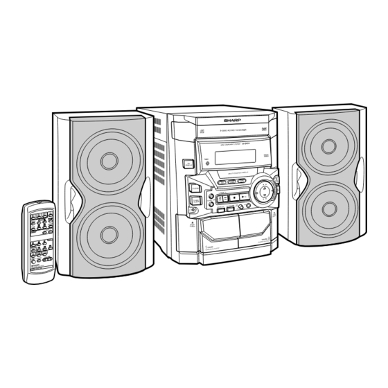
MINI COMPONENT SYSTEM
CD-BK133W
CD-BK133W Mini Component System consisting of
CD-BK133W (main unit) and CP-BK133 (speaker system).
• In the interests of user-safety the set should be restored to its
original condition and only parts identical to those specified be
used.
This document has been published to be used
for after sales service only.
The contents are subject to change without notice.
CD-BK133W
No. S0173CDBK133W
Page
Advertisement
Table of Contents

Related Manuals for Sharp CD-BK133W


Summary of Contents for Sharp CD-BK133W
-
Page 1: Table Of Contents
MINI COMPONENT SYSTEM CD-BK133W MODEL CD-BK133W Mini Component System consisting of CD-BK133W (main unit) and CP-BK133 (speaker system). • In the interests of user-safety the set should be restored to its original condition and only parts identical to those specified be used. -
Page 2: Safety Precaution For Service Manual
CD-BK133W SAFETY PRECAUTION FOR SERVICE MANUAL WARNINGS THE AEL (ACCESSIBLE EMISSION LEVEL) OF THE LASER POWER OUTPUT IS LESS THAN CLASS 1 BUT THE LASER COMPONENT IS CAPABLE OF EMITTING RADIATION EXCEEDING THE LIMIT FOR CLASS 1. THEREFORE IT IS IMPORTANT THAT THE FOLLOWING PRECAUTIONS ARE OBSERVED DURING SERVICING TO PROTECT YOUR EYES AGAINST EXPOSURE TO THE LASER BEAM. -
Page 3: Names Of Parts
CD-BK133W NAMES OF PARTS CD-BK133W Display 1. Disc Number Indicators 1 2 3 4 2. Timer Indicator 3. Tape 2 Record Indicator 4. Sleep Indicator 5. Extra Bass Indicator 6. CD or Tuner Memory Indicator 7. FM Stereo Mode Indicator 8. - Page 4 CD-BK133W CD-BK133W Remote control 1. Remote Control Transmitter 2. Disc Number Select Buttons 3. CD Pause Button 4. CD Memory Button 5. CD Clear Button 6. CD Track Down or Fast Reverse Button 7. CD Track Up or Fast Forward Button 8.
-
Page 5: Operation Manual
CD-BK133W OPERATION MANUAL System Connections Setting the AC voltage selector Setting the FM/AM Span Selector Check the setting of the AC voltage selector located on the rear panel before plug- ging the unit into an AC socket. If necessary, adjust the selector to correspond to the AC power voltage used in your area. -
Page 6: Voltage Selection
CD-BK133W Remote Control Troubleshooting If trouble occurs Test of the remote control When this product is subjected to strong external interference (mechanical shock, Face the remote control directly to the remote excessive static electricity, abnormal supply voltage due to lightning, etc.) or if it is Remote sensor sensor on the unit. -
Page 7: Disassembly
CD-BK133W DISASSEMBLY Note 1: How to open the changer manually. (Fig. 8-1) Caution on Disassembly 1. In this state, turn fully the lock lever in the arrow direction through Follow the below-mentioned notes when disassembling the hole on the loading chassis bottom. - Page 8 CD-BK133W (G2)x1 Lock Lever (H2)x1 Display (G1)x1 ø3x10mm Mic PWB (H1)x11 ø3x10mm CD Player Unit Tape (Bottom View) Front Mechanism Panel Open (K1)x6 Cassette ø3x10mm Holder Figure 8-1 (J2)x1 (J1)x1 ø3x10mm Lug Wire Clamp Lever Headphones Figure 8-4 (L2)x1 CD Player Unit...
- Page 9 CD-BK133W (P2)x3 Mechanism (N1)x1 Slide CD Servo ø3x8mm Chassis (N2)x2 (P1)x1 (P1)x1 Slide (N3)x2 Chassis (N2)x2 Figure 9-1 Figure 9-2 CP-BK133 These speakers CP-BK133 is available in assembles only and may not be disassembled. – 9 –...
-
Page 10: Removing And Reinstalling The Main Parts
CD-BK133W REMOVING AND REINSTALLING THE MAIN PARTS TAPE MECHANISM SECTION TAPE 2 Clutch Ass'y Perform steps 1 to 5 and 10 of the disassembly method to remove the tape mechanism. Record/Playback Head How to remove the record/playback and erase heads (TAPE 2) (See Fig. 10-1) 1. -
Page 11: Adjustment
CD-BK133W CD MECHANISM SECTION Loading Motor Perform steps 1, 2, 3, 11,12, 13 and 14 of the disassembly Loading Slide method to remove the CD mechanism. Motor PWB Chassis How to remove the loading motor (See Fig. 11-1) (A1)x1 (A1)x2 1. - Page 12 CD-BK133W • FM RF TUNER SECTION Signal generator: 1 kHz, 40 kHz dev., FM modulated fL: Low-range frequency fH: High-range frequency Test Stage Frequency Frequency Setting/ Instrument • AM IF/RF Display Adjusting Connection Point Signal generator: 400 Hz, 30%, AM modulated FM Band —...
-
Page 13: Block Diagram
CD-BK133W DISC CLAMP NUMBER OPEN/ CLOSE T/T UP/DOWN LOADING TO MAIN SECTION TO DISPLAY SECTION 46 47 LC78641E SERVO/SIGNAL CONTROL XOUT 17 25 CONT5 SLDO SPDO M63001FP VCC1 VCC4 FOCUS/TRACKING/ VCC2 SPIN/SLED VCC3 DRIVER +3.3V +3.3V +3.3V 26 27 CONSTANT... - Page 14 CD-BK133W ANTENNA IC301 TA7358AP SO302 FM FRONT END FM IF 10.7 MHz T302 CF302 BF301 X351 450kHz CF351 456 kHz B.P.F T351 CF352 AM IF FM L312 AM LOOP T301 ANTENNA OSC BUFF CNP302 IC303 Q302 LA1832S AM TRACKING FM IF DET.
- Page 15 CD-BK133W IC704 FL701 KIA7042A FL DISPLAY Q701 SYSTEM RESET LED722 RX701 REMOTE SENSOR IC701 VLOAD IX0362AW(1/2) AVD1 SYSTEM AVDD MICROCOMPUTER SW701-SW703 SW709-SW721 SW723-SW725 SW601 SPAN 4 5 6 7 8 11 12 16 1 7 20 21 23 22 24...
-
Page 16: Schematic Diagram / Wiring Side Of P.w.board
CD-BK133W FM SIGNAL PLAYBACK SIGNAL RECORD SIGNAL CD SIGNAL C605 C604 MIC SIGNAL 10/50 0.022 C615 C616 + – R-CH 220P 220P – C607 INTERFACE A_GND 10/50 LOUT C609 C611 R615 – – 0.1(ML) 0.1(ML) L-CH 3.9K LBASS C613 CD_GND –... - Page 17 CD-BK133W MAIN PWB-A (1/3) R389 C619 220P + – C606 22/50 C608 VREF 10/50 – INTERFACE ROUT C612 R616 – C610 0.1(ML) 3.9K 0.1(ML) RBASS C614 – 0.0027(ML) RTRE C618 1/50 C630 RSELO 1/50 – A_10V A_10V C624 1/50 DECK...
- Page 18 CD-BK133W AM TRACKING fL C331 C342 T303 0.047 0.022 C323 0.022 R358 C332 AM ANTENNA 3.3K 0.022 VD301 SVC348S D301 1SS133 D302 C335 1SS133 560P R336 C334 R323 T306 AM OSC. AM BAND COVERAGE fL C303 C351 IC301 AM LOOP 0.022...
- Page 19 CD-BK133W C373 R364 R363 0.015 C342 6.8K 6.8K (ML) R365 0.022 C371 R361 1/50 1.5K R358 3.3K R362 C372 1.5K 1/50 IC303 AM OSC AM OSC VSM AM LOW FM/AM R-CH L-CH MO/ST LA1832S R351 RF IN 5.6K FM IF...
- Page 20 CD-BK133W IC901 FM SIGNAL STK402-070N POWER AMP. 1 2 3 4 5 6 7 8 9 10 11 12 13 14 R920 R921 D901 1SS133 C903 220P C912 R904 220P R911 C911 F902 LR901 T2.5A L 250V C904 C910 R905...
- Page 21 CD-BK133W R943 SOK901 CNS902 M901 – MOTOR C946 R931 47/16 R930 C945 10/50 HEADPHONES PWB-D PW901A PW901B JK901 HEADPHONES SP_L-CH SP_R-CH SO901 SPEAKER – SP_L-CH_GND TERMINAL – SP_R-CH_GND R926 C944 R942 100/16 Q903 KTC3199 GR R927 AC POWER SUPPLY CORD...
- Page 22 CD-BK133W FL701 FL DISPLAY KRC10 4.9V 10 11 12 13 14 15 16 17 18 19 20 21 22 23 24 25 26 27 28 29 30 31 32 33 – R744 81 82 83 84 85 86 87 88 89 90 91 92 93 94 95 96 97 98 99 100 –20DB ATT...
- Page 23 CD-BK133W DISPLAY PWB-B R779 Q701 KRC107 M 4.9V 30 31 32 33 –25.4V CD INT –25.6V WRO(DSP) R745 CD CE 100K CD DO C707 CD DI 1/50 CD CLK R744 RES OUT CLAMP SW CD GND FFC701 C701 0.022 TUN SM 97 98 99 100 –20DB ATT...
- Page 24 CD-BK133W CD SERVO PWB-E CD SIGNAL VREF TIN1 0.047 FIN1 FIN2 1.5M TIN2 2.2/50 47/10 0.022 6.8K LA9235M SERVO AMP. 100P 0.01 FIN1 100/10 FIN2 RFSW TIN1 TIN2 10/16 1.2K REF1 VREF 0.01 0.33 RFEV LDOF 0.047 ODRV AGON EFBL...
- Page 25 CD-BK133W 100P 100P 3.3K 100P 100P 100P 4.7K 100P 100P 100P 1.5M 2.2/50 2.2µH 100/10 PD01 SBCK R-CH PD02 AGND VVSS SBSY P16 1 - B L-CH PCKIST SFSY CNS601 DGND FROM MAIN PWB VVDD DATA 1.2K DATACK SLCIST LRSY...
- Page 26 CD-BK133W P30 4 - A FROM TO CD SERVO PWB TAPE MECHANISM GND CNP11 FROM FROM TAPE 2 RECORD/ TAPE 1 PLAYBACK PLAYBACK HEAD HEAD CNS601 P31 11 - F P31 10 - F 1 2 3 4 5 C142...
- Page 27 CD-BK133W MAIN PWB-A HEADPHONES PWB-D JK901 HEADPHONES Q906 Q904 C908 C910 C911 R915 C914 R910 R914 C912 R909 C909 R912 R908 R911 R920 C913 R921 PW901B 5 4 3 2 1 R903 R907 R904 C907 R905 230-0133W-003 C906 C905 R902...
- Page 28 CD-BK133W DISPLAY PWB-B L701 C715 R770 D707 D711 D710 R744 C702 D708 FL701 R705 C707 Q707 R772 C717 C719 R722 C713 R773 IC701 RX701 R769 3 2 1 25 3 Q705 R709 D703 1 2 3 C720 Q708 B C E...
- Page 29 CD-BK133W P30 5 - A TO CD SERVO PWB CNP12 CNS702 1 2 3 4 5 6 7 8 9 10 BI702 C708 FL701 R748 SW701 ON/STAD-BY R749 IC701 LED722 25 35 R721 R720 R719 RD13 RD04 RD05 SW702 SW714...
- Page 30 CD-BK133W P29 9 - A P26 4 - A FROM FROM MAIN PWB DISPLAY PWB CNS601 CNS702 CD SERVO PWB-E 1 2 3 4 5 1 2 3 4 5 6 7 8 9 10 CNP11 CNP12 B C E...
- Page 31 CD-BK133W TAPE MECHANISM P28 2 - G ASSEMBLY TO DISPLAY PWB SOK3 TAPE MECHANISM PWB-F FFC702 7 9 11 8 10 SOLENOID SOLENOID TAPE MOTOR TAPE 2 COLOR TABLE TAPE 1 RECORD/PLAYBACK ERASE HEAD BROWN PLAYBACK HEAD HEAD RD( R)
-
Page 32: Voltage
CD-BK133W VOLTAGE IC701 IC901 NO. VOLTAGE NO. VOLTAGE NO. VOLTAGE NO. VOLTAGE NO. VOLTAGE NO. VOLTAGE NO. VOLTAGE 0.7 V 4.86 V 1.6 V 1.6 V 3.3 V 1.6 V 1.6 V 3.3 V 4.97 V 1.8 V 4.85 V 1.6 V... -
Page 33: Notes On Schematic Diagram
CD-BK133W NOTES ON SCHEMATIC DIAGRAM • Resistor: • The indicated voltage in each section is the one measured To differentiate the units of resistors, such symbol as K and by Digital Multimeter between such a section and the chas- M are used: the symbol K means 1000 ohm and the symbol sis with no signal given. -
Page 34: Waveforms Of Cd Circuit
CD-BK133W WAVEFORMS OF CD CIRCUIT Stopped 1999/04/05 17:33:17 Stopped CH1=500mV CH3=1V CH4=1V 500ms/div CH1=500mV CH3=500mV 500ms/div DC 10:1 DC 10:1 DC 10:1 (500ms/div) DC 10:1 DC 10:1 (500ms/div) NORM:20kS/s NORM:20kS/s PDO1 IC2 1 IC2 24 PDO2 IC2 2 IC2 23... -
Page 35: Troubleshooting
CD-BK133W TROUBLESHOOTING When the CD does not function When the CD section does not operate when the objective lens of the optical pickup is dirty, this section may not operate. Clean the objective lens, and check the playback operation. When this section does not operate even after the above step is taken, check the following items. - Page 36 CD-BK133W Stopped (1) Focus-HF system check. CH1=500 mV CH3=500 mV 500 ms/div DC 10:1 DC 10:1 (500 ms/div) NORM:20 kS/s Although a CD is inserted and the cover is closed, "NO DISC" is displayed. Press the OPEN/CLOSE switch (SW1) without inserting a disc, and try starting the playback operation.
- Page 37 CD-BK133W (2) Tracking system check. Check the TE waveform at pin 18 on IC1. The tracking servo is not activated. If the waveform shown in Figure 37-1 appears and soon after Check the peripheral circuits at pins 18 and 19 on IC1, pin 16 on NO DISC appears ? IC2, and CNS1A/B.
- Page 38 CD-BK133W (4) PLL system check. Stopped 1999/04/05 17:33:17 CH1=500 mV CH3=1 V CH4=1 V 500 ms/div DC 10:1 DC 10:1 DC 10:1 (500 ms/div) NORM:20 kS/s PDO1 When a disc is loaded, start play operation. The HF waveform is normal, but the TOC data cannot be PDO2 read.
-
Page 39: Function Table Of Ic
CD-BK133W FUNCTION TABLE OF IC IC2 VHiLC78641E-1: Servo/Signal Control (LC78641E) (1/2) Terminal Name Input/Output Setting in Reset Function Pin No. PD01 Output — For PULL Phase-comparison output terminal for built-in VCO control. PD02 Output Input Phase-comparison output terminal for built-in VCO control. - Page 40 CD-BK133W IC2 VHiLC78641E-1: Servo/Signal Control (LC78641E) (2/2) Terminal Name Input/Output Setting in Reset Function Pin No. LVDD Input — L channel Power terminal for L channel. LCHO Output 1/2VDD D/A converter L channel output terminal. LVSS — — Ground terminal for L channel. Surely connected to 0 V.
- Page 41 CD-BK133W IC2 VHiLC78641E-1: Servo/Signal Control (LC78641E) PDO1 SBCK PDO2 VVSS SBSY PCKIST SFSY VVDD DATA DATACK SLCIST LRSY SLCO ASDFIN EFMIN ASDACK JITTV ASLRCK JITTC XVSS LC78641E XOUT PH(RFENV) XVDD RVDD VREF RCHO ADAVDD RVSS ADAVSS LVSS PHREF LCHO BHREF...
- Page 42 CD-BK133W IC701 RH-iX0362AWZZ: System Microcomputer (IX0362AW) (1/2) Pin No. Port Name Terminal Name Input/Output Function Input (+) POWER SUPPLY. -20 dB ATT Output -20 dB ATTENUATOR. NO USE Output DSA_STB Input/Output DSA STRUBE T_BIAS Output TAPE RECORD BIAS. T_T1/T2 Output TAPE T1/T2 CHANGE.
- Page 43 CD-BK133W IC701 RH-iX0362AWZZ: System Microcomputer (IX0362AW) (2/2) Pin No. Port Name Terminal Name Input/Output Function P124 T 1 RUN Input TAPE 1 RUN PULSE INPUT. P123 T 2 RUN Input TAPE 2 RUN PULSE INPUT. P122 CD CLAMP SW Input CD CHANGER CLAMP SWITCH.
- Page 44 CD-BK133W IC601 VHiLC75341/-1: Audio Processor (LC75341) ROUT LOUT LBASS RBASS LTRE RTRE LSEL0 RSEL0 R1 R2 24 23 22 21 20 19 18 17 16 15 14 13 LC75341 10 11 12 Figure 44 BLOCK DIAGRAM OF IC – 44 –...
- Page 45 CD-BK133W IC3 VHiM63001FP-1: Focus/Tracking/Spin/Sled Driver (M63001FP) Terminal Pin No. Function Name CH2 inverted input. LD_M+ CH1 inverted input. CH1 output offset control. LD_M– CH1 inverted output. VCC4 CH1 non-inverted output. LOADING M+ CH2 inverted output. CH2 non-inverted output. FO– LOADING M–...
-
Page 46: Fl Display
CD-BK133W FL DISPLAY FL701 VVKSVA9MS13-1: FL Display h j k – 46 –... - Page 47 PARTS GUIDE MINI COMPONENT SYSTEM CD-BK133W MODEL CD-BK133W Mini Component System consisting of CD-BK133W (main unit) and CP-BK133 (speaker system). “HOW TO ORDER REPLACEMENT PARTS” To have your order filled promptly and correctly, please furnish the For U.S.A. only following information.
- Page 48 CD-BK133W PRICE PRICE DESCRIPTION PARTS CODE DESCRIPTION PART CODE RANK RANK T301 RCILB0065AWZZ AC FM OSC. CD-BK133W T302 RCILI0017AWZZ AB FM IF T303 RCILA0052AWZZ AE AM Antenna INTEGRATED CIRCUITS T306 RCILB0058AWZZ AC AM OSC. T351 RCILI0019AWZZ AD AM IF VHILA9235M/-1 AQ Servo Amp.,LA9235M...
- Page 49 CD-BK133W PRICE PRICE DESCRIPTION PART CODE PARTS CODE DESCRIPTION RANK RANK 0.0047 µF,50V C106,107 92L2700056143 560 pF,50V C405 92L2700047243 AC 100 µF,16V,Electrolytic AB 1 µF,50V,Electrolytic C108 VCEAZA1CW107M J C406 VCEAZA1HW105M J 0.001 µF,50V AB 4.7 µF,50V,Electrolytic C109 92L2700010243 C407 VCEAZA1HW475M J AC 220 µF,6.3V,Electrolytic...
- Page 50 CD-BK133W PRICE PRICE PART CODE DESCRIPTION PARTS CODE DESCRIPTION RANK RANK 92L32150470008 47 ohms,1/8W R365 VRD-ST2CD103J AA 10 kohm,1/6W 92L32150221008 220 ohms,1/8W R372~374 VRD-ST2CD102J AA 1 kohm,1/6W R21,22 92L32150471008 470 ohms,1/8W R375 VRD-ST2CD821J AA 820 ohms,1/6W 92L32150103008 10 kohm,1/8W R376...
- Page 51 CD-BK133W PRICE PRICE DESCRIPTION PART CODE PARTS CODE DESCRIPTION RANK RANK R914,915 VRD-ST2CD4R7J AA 4.7 ohms,1/6W LR901 92L5650133W000 Relay R916,917 VRD-ST2CD152J AA 1.5 kohms,1/6W LUG1 92L16310130000 Lug Terminal R918,919 VRD-ST2CD103J AA 10 kohm,1/6W 92LMTR2790CASY J BB Motor with Chassis [Spindle]...
- Page 52 CD-BK133W PRICE PRICE DESCRIPTION PARTS CODE DESCRIPTION PART CODE RANK RANK 201-11 92L80210100001 AE Button,Function 258- 5 92PF514-133 AL Pinch Roller 201-12 92L80410100001 Volume Ring 258- 6 92PF19S-31 AL Belt,FF/REW [Tape 2] 201-13 92L80230100002 AE Button,Disk Skip 258- 7 92LPFF19N-11...
- Page 53 CD-BK133W PRICE DESCRIPTION PART CODE RANK CP-BK133 SPEAKER BOX PART 92L2391133W000 Speaker Box Ass’y PACKING PARTS 92LPA044 Packing Add. 92L19450600201 Polyethylene Bag,Speaker – 6 –...
- Page 54 CD-BK133W CD-BK133W 306-2 306-1 306-3 703x2 305x2 PWB-H Figure 7 CD MECHANISM EXPLODED VIEW – 7 –...
- Page 55 CD-BK133W CD-BK133W BELT CONNECTION 202-1 FF/REW FF/REW 607x8 ROLLER ROLLER Tape ASS'Y ASS'Y Motor 610x3 FLYWHEEL FLYWHEEL ASS'Y ASS'Y MAIN BELT TAPE 1 TAPE 2 610x2 258-1, 258-2, 258-3, 258-4, 258-5, 258-6, 258-7, 258-8, 258-9, 202-2 258-10, 258-11 608x11 PWB-F...
- Page 56 PWB-G 243x4 PWB-E 232x4 CABINET EXPLODED VIEW (2/2) © COPYRIGHT 2001 BY SHARP CORPORATION SHARP CORPORATION ALL RIGHTS RESERVED. AV Systems Group Audio Systems Division Higashihiroshima, Hiroshima 739-0192, Japan No part of this publication may be reproduced, stored in a retrieval system, or transmitted in...
Need help?
Do you have a question about the CD-BK133W and is the answer not in the manual?
Questions and answers