Table of Contents
Troubleshooting

Related Manuals for RITAL GROUP RI-F325HCR3TEVI-TR


Summary of Contents for RITAL GROUP RI-F325HCR3TEVI-TR
- Page 1 COMMERCIAL HEATING & COOLING HEAT PUMP installation and instruction manual IMPORTANT NOTE: Thank you very much for purchasing our product. Before using your unit, please read this manual carefully and keep it for future reference.
-
Page 3: Table Of Contents
Content I. Foreword ..................................1 II. Product Specification .............................. 4 1. Dimension .................................4 2. Technical parameter ..............................8 III. Installation ................................9 1. Product handling ..............................9 2. Installation site selection ............................9 3. Installation Foundation ............................10 4. Water system piping layout ..........................11 4.1. -
Page 4: Foreword
I. Foreword Please read this instruction carefully before installation and use. This instruction supports required messages for installation,adjustment and maintenance. NEW ENERGY heat pump products are produced strictly follow the design standards to make sure that units can run safely and high-efficiently, support high reliability and outstanding adaptability. NEW ENERGY won’t take any responsibilities for the damages on people or units caused by improper installation,adjustment,maintenance and operations contrary to the instruction. - Page 5 Unit must run in the specific range of this instruction It is strictly prohibited to refit the unit or modify the parameters . It may cause damages to units ,even injury to people if not follow the notes above. Water system installation Filters,three-way pipe and valves for sewage disposal shall be installed at the inlet and outlet water pipe.
- Page 6 discharge work of the unit shall be carried out as follows: Operational guideline: Turn on the wash port at the bottom of inlet water pipe to drain water over.Keep the wash port open until the next use before closing (To confirm that the water in the heat exchanger is drained over,please open the vent valve of the water system) Cleaning,pressurizing and leak detective of engineering water system need to disconnect the water way of the unit.
-
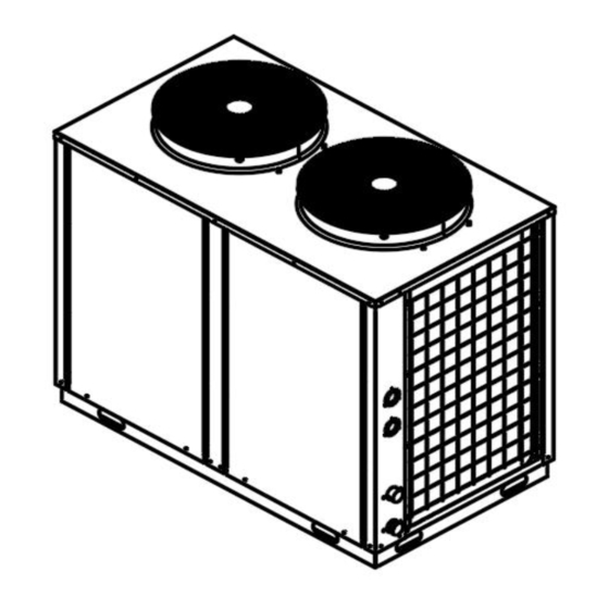
Page 7: Product Specification
II. Product Specification Dimension Unit:mm Model: RI-F325HCR3T 1555 1035 1343 EVI-TR... - Page 8 Unit:mm Model RI-F450HCR3T 1150 1000 2330 EVI-TR...
- Page 9 Unit:mm Model RI-F860HCR3T 2050 1000 2358 1324 EVI-TR...
- Page 10 Unit:mm Model RI-F1680HCR3 1300 2400 2415 2123 1400 TEVI-TR...
-
Page 11: Technical Parameter
Technical parameter 1680HCR3T Model: RI-F 325HCR3TEVI-TR 450HCR3TEVI-TR 860HCR3TEVI-TR EVI-TR Ambient temp.: (DB/WB) 7°C/6°C; Water Outlet temp.: 45°C Heating Capacity (kW) 32.7 Power Input (kW) 9.09 12.8 24.5 45.7 3.52 3.51 3.68 Ambient temp.: (DB/WB) -12°C/-14°C; Water Outlet temp.: 41°C Cooling Capacity (kW) 20.5 Power Input (kW) 8.36... -
Page 12: Installation
III. Installation Product handling Confirm the delivery route of the unit, which is enough for the package box of the unit to pass safely. Remove the packing box when the unit is transported near the installation position. During handling, the inclination of the unit shall not be more than 15 ° to prevent the unit from overturning. ... -
Page 13: Installation Foundation
The place with strong ground strength, which is not easy to cause resonance and noise A drainage ditch must be built around the machine to discharge the condensate; The unit installed on the roof must be provided with anti typhoon and anti lightning measures, and snow ... -
Page 14: Water System Piping Layout
The installation base of concrete of the unit is as follows: Unit:mm Model RI-F325HCR3TEVI-TR 1100 RI-F450HCR3TEVI-TR RI-F860HCR3TEVI-TR 1314 1254 RI-F1680HCR3TEVI-TR Water system piping layout 4.1. Pipe size Inlet and outlet pipe diameter of the unit Please refer to the performance specification for inlet and outlet pipe diameters. -
Page 15: Installation Requirements
The pressure relief device operates regularly to remove the calcium carbonate deposition and ensure the smooth operation of the device; For the closed water heater directly connected with water source, the rated pressure shall be at least 0.6MPa; For appliances with a capacity of more than 15L and cannot be emptied through the water outlet installed in the water pipe, a discharge device which can work only by using tools shall be installed;... - Page 16 before entering the water. Quality control of domestic hot water Domestic hot water is domestic water. Tap water or treated water is required. Lake water, river water and untreated groundwater are strictly prohibited. C. Applicable water quality standards of unit chloridion(CL)...
-
Page 17: Water System Piping
Water system piping Solution 1... - Page 18 Solution 2...
-
Page 19: Winter Antifreeze
Winter antifreeze In winter, when the temp. is lower than 0℃, the unit does not run for a long time (including the commissioning unit after water test). In order to prevent the freezing crack of the internal pipelines of the unit, the water discharge work of the unit shall be carried out as follows: Operational guideline:... -
Page 20: Electrical Wiring Diagram
IV. Electrical wiring diagram Notice The unit must use the special power supply, the power supply voltage conforms to the rated voltage. Wiring must be carried out by a professional following the wiring diagram on the fuselage. Pay attention to the selection of the maximum current or maximum power of the unit for external cables of ... - Page 21 The wire controller shall be fixed with screws in the indoor environment more than 1.5m above the ground. It is forbidden to be installed in the humid, rainy, acidic, corrosive environment where the light directly shines. Open the door of the electric cabinet, turn off the power first, do not remove or move any electrical ...
-
Page 22: Control Function
V. Control function Controller panel Interface overview Key switching Note: In the branch interface (except the countdown interface and the main interface), if there is no button for 1 minute, the system will automatically return to the main interface. When "▲"... -
Page 23: Interface Introduction
up > to achieve up page turning. When the right side of the interface says "▼", it means that you can press < to scroll down > on this interface to scroll down. When the interface prompts "operation is currently prohibited, but operation is available XX seconds later", ... -
Page 24: Countdown Interface
Cooling Inquiry 3.2. Countdown interface countdown main interface Chinese Stand by 5S later ———→ Welcome Cooling 15:30 Note: ① In the countdown interface at starting up, press <up> or <down> to switch language directly. 3.3. Main interface 【2】 【3】 ↑ ↑... -
Page 25: Timing Set Interface
the module number 00~15 corresponds to the module address setting of 0 to F of SR1 on control panel. 【2】Indicates to press <function> key to return to menu of previous level. 【3】Indicates to press <enter> key to reset fault. Indicate to return to the main interface if there is no fault at present. -
Page 26: Status Inquiry
3.6. Status inquiry After entering the status inquiry interface, press <enter> key to switch module status inquiry. 【3】 【4】 ↑ ↑ <enter> <up> <up> >1 Timing setting System output: 00#module output: ▲ Analog of 00#module:▲ ———→ ———→ ———→ ←——— ←——— ←———... -
Page 27: Historical Fault Inquiry
inquiry. 【2】 Indicate the version and function code corresponding to control. Press < down > to continue the inquiry. 【3】 Indicates to press <function> key to return to menu of previous level. 3.8. Historical fault Inquiry After entering the Advanced function , press <down>or<up> to select inquiry of historical fault. 【1】... -
Page 28: Password Change
【1】Remind the users to input password including repair and manufacturer password. 【2】Indicates to press < function > key to shift the input password at present. Press up or down to input the current password value. 【3】Press < enter > key to confirm the input password and enter parameter setting. 【4】Indicates to return to the interface of previous level by pressing <function>... -
Page 29: Parameter Setting
Function Effective interface of key Password Advanced function <Function> User password Repair setting Main interface Repair password <Enter + Function> Manufacturer setting Manufacturer password Maintenance setting <Enter + Function> Countdown interface Maintenance password 5.2. Parameter setting 【3】 【5】 Parameter setting Parameter setting of type B of type B... - Page 30 Description: 【1】Indicates to press <function> key to cancel the changed parameter value and return to the interface of previous level. 【 2 】 Indicates to enter the parameter setting item and determine the content of changed parameter by pressing <enter> key. 【3】Indicate the name of parameter group.
-
Page 31: Module Control And Linkage Wiring
Control mode Hot water mode Hot water mode Hot water setting 30~60 ℃ temp.. Hot diff 1~30 ℃ Remember function Dis./Enable Enable Auto on Dis./Enable Dis. Linkage Switch Dis./Enable Dis. 6. Module control and linkage wiring 1) Parameter setting required for module control Under shutdown state, press "Function "... - Page 33 4) Linkage control wiring diagram and parameter setting requirements Linkage control is not used by default when the unit leaves the factory, if the user needs to use linkage control. Turn【Linkage Switch】into 【Enable】if needed. After the linkage control takes effect, when the linkage terminal of the unit is closed and the switch key ...
-
Page 34: Trial Running
VI. Trial running Note before trial running After repeated flushing and drainage of the water system pipelines, the water quality cleanliness shall be confirmed to meet the requirements. The water pump shall be turned on after the pipeline system refuses and empties, and the water flow and outlet pressure shall be confirmed to meet the requirements. -
Page 35: Trouble Shooting
If it is necessary to cut off the power supply because the unit has stopped running for a long time, remember to electrify the unit 8 hours before starting up again and preheat the compressor. Trouble shooting 1.1. Control protection function list 1) Cut-out protection 2) Protection of low water flow 3) Phase sequence protection... -
Page 36: Trouble Shooting
Fault self-recovery: check the fault table. 4) Manual reset (M) Alarm after the fault clearance, only by manual reset controller; 1) 2) 3) Type failure can also be manually reset. 1.3. Trouble shooting Faults Possible cause Trouble shooting There is air in the system or other Remove the gas from the nozzle and non-condensable gas condenser fin vacuum the condenser fins again if... - Page 37 Refrigerant leakage or filling is not Check for leakage or fill with sufficient enough refrigerant. Insufficient air volume Check fan steering. Low suction pressure(Heating) Air short circuit Eliminate the cause of air short circuit. Failure of four-way valve or sensor, replace Insufficient defrost operation if necessary.
-
Page 38: Maintenance
High pressure protection or low See front suction and exhaust pressure fault pressure protection. section. The contactor coil is burnt out. Replace the damaged components. Power phase sequence connection Reconnect and adjust any two connections error. in the three phases. Water system failure, water flow Check the water system. - Page 39 runs when units operate. The following preparations shall be made when the unit is restarted after any prolonged outage: Thoroughly inspect and clean the unit. Clean the plumbing system. Inspect water pump, regulator and other equipment of water piping system. Tighten all wire connections Power on for 12 hours before starting Parts replacement...
- Page 40 When the environment temp. is lower than 0 ℃, heating efficiency with the outdoor temp. falls. For the air-cooled heat pump units in the cold region heating operation stability, complement part of heat loss due to defrost, when a user area winter minimum temp. in the range of 0 to 10 ℃, equipped with auxiliary electric heater may be considered.
- Page 44 Website: www.rital.com.tr Whatsapp: +90 530 936 74 97 Address: Baglarcesme mah. dogan araslı Bulv no:165 demirpark avm kat:2 ofis:35 Esenyurt İstanbul...
Need help?
Do you have a question about the RI-F325HCR3TEVI-TR and is the answer not in the manual?
Questions and answers