Table of Contents
Advertisement
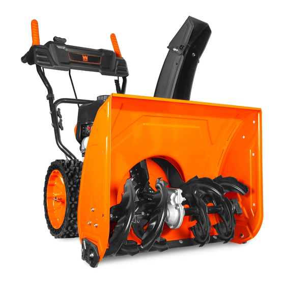
MODEL SB209E
24-INCH TWO-STAGE
SNOW BLOWER
Instruction Manual
NEED HELP? CONTACT US!
Have product questions? Need technical support? Please feel free to contact us:
1-847-429-9263 (M-F 8AM-5PM CST)
TECHSUPPORT@WENPRODUCTS.COM
IMPORTANT: Your new tool has been engineered and manufactured to WEN's highest standards for dependability,
ease of operation, and operator safety. When properly cared for, this product will supply you years of rugged,
trouble-free performance. Pay close attention to the rules for safe operation, warnings, and cautions. If you use
your tool properly and for its intended purpose, you will enjoy years of safe, reliable service.
WENPRODUCTS.COM
For replacement parts and the most up-to-date instruction manuals, visit
Advertisement
Table of Contents

Related Manuals for Wen SB209E


Summary of Contents for Wen SB209E
- Page 1 1-847-429-9263 (M-F 8AM-5PM CST) TECHSUPPORT@WENPRODUCTS.COM IMPORTANT: Your new tool has been engineered and manufactured to WEN’s highest standards for dependability, ease of operation, and operator safety. When properly cared for, this product will supply you years of rugged, trouble-free performance. Pay close attention to the rules for safe operation, warnings, and cautions. If you use your tool properly and for its intended purpose, you will enjoy years of safe, reliable service.
-
Page 2: Table Of Contents
Exploded View & Parts List ................33 Warranty Statement ..................44 WENPRODUCTS.COM To purchase accessories and replacement parts for your tool, visit Magnetic Oil Dipstick (Model 55201) 100-Foot Extension Cord (Model PC1123) 50-Foot Extension Cord (Model PC5124) High-Altitude Kit (Part SB209E-HA36, SB209E-HA68) -
Page 3: Welcome
SPECIFICATIONS SNOW BLOWER Model Number SB209E Stages 2-Stage Maximum Clearing Width 24 in. Maximum Clearing Height 20 in. Throwing Distance 30 feet Auger Diameter 10 in. Tires 13 in. x 4.1 in. tubeless Speed Control 6 speeds forward, 2 speeds backwards... -
Page 4: Introduction
INTRODUCTION Thanks for purchasing the WEN snow blower. Refer to the illustration below for the location of the serial number on the control panel label. Record the snow blower information in the spaces provided below. If assistance for informa- tion or service is required, please contact customer service by calling 1-847-429-9263, M-F 8-5 CST; you will be asked to provide the following snow blower information when calling. -
Page 5: Safety
WEN reserves the right to change this product and specifications at any time without prior notice. At WEN, we are continuously improving our products. If you find that your tool does not exactly match this manual, please visit wenproducts.com for the most up-to-date manual or contact customer service at 1-847-429-9263, M-F 8-5 CST. - Page 6 GENERAL SAFETY RULES WARNING! Read all safety warnings and all instructions. Failure to follow the warnings and instructions may result in electric shock, fire and/or serious injury. Safety is a combination of common sense, staying alert and knowing how your item works. The term “power tool” in the warnings refers to your mains-operated (corded) power tool or battery-operated (cordless) power tool.
- Page 7 GENERAL SAFETY RULES WARNING! Read all safety warnings and all instructions. Failure to follow the warnings and instructions may result in electric shock, fire and/or serious injury. Safety is a combination of common sense, staying alert and knowing how your item works. The term “power tool” in the warnings refers to your mains-operated (corded) power tool or battery-operated (cordless) power tool.
-
Page 8: Snow Blower Safety Warnings
SNOW BLOWER SAFETY WARNINGS DANGER! CARBON MONOXIDE Using a snow blower indoors CAN KILL YOU IN MINUTES. Snow blower exhaust contains carbon monoxide (CO). This is a poison gas you cannot see or smell. If you can smell the snow blower exhaust, you are breathing CO. - Page 9 SNOW BLOWER SAFETY WARNINGS WARNING! Do not let comfort or familiarity with the product replace strict adherence to product safety rules. Failure to follow the safety instructions may result in serious personal injury. OPERATING ENVIRONMENT TRAINING 1. Using a snow blower indoors can kill you in min- 1.
- Page 10 SNOW BLOWER SAFETY WARNINGS WARNING! Do not operate the power tool until you have read and understood the following instructions and the warning labels. 5. If using the electric start function, ensure the exten- 7. Do not operate the machine under the influence of sion cord is of the proper gauge.
-
Page 11: Electrical Information
OFF position and the electric current is rated the same as the current stamped on the motor nameplate. Running at a lower voltage will damage the motor. TIP: WEN offers 12-gauge, outdoor-rated, grounded three-wire extension cords in 50-foot and 100-foot lengths (Model PC1123, PC5012), available for purchase at wenproducts.com. - Page 12 UNPACKING & PACKING LIST PACKING LIST Snow Blower Components Qty. Snow Blower Engine Keys (hanging on the snow blower) Handle Assembly Qty. Lower Handle Upper Handle Cable Clips (pre-installed on the lower handle) M8x16 Bolts (pre-installed on snow blower body) M8x45 Bolts (pre-installed on the lower handle) M8 Lock Knobs (pre-installed on the lower handle) Cleaning Tool Assembly...
-
Page 13: Know Your Snow Blower
KNOW YOUR SNOW BLOWER Refer to the following diagrams to become familiarized with all the parts and controls of your snow blower. The components will be referred to later in the manual for assembly and operation instructions. Speed Control Lever Handle Speed Control Rod Upper Handle... -
Page 14: Assembly & Adjustments
ASSEMBLY & ADJUSTMENTS WARNING! Always be sure that the snow blower’s engine is OFF and no extension cord is connected before adjusting, adding accessories, or checking a function on the machine. INSTALLING THE LOWER HANDLE Fig. 1 1. Install the lower handle (Fig. 1 - 1) on the back of the snow blower body using the four included M8x16 bolts (Fig. - Page 15 ASSEMBLY & ADJUSTMENTS WARNING! Always be sure that the snow blower’s engine is OFF and no extension cord is connected before adjusting, adding accessories, or checking a function on the machine. INSTALLING THE DRIVE CONTROL ROD Fig. 3 NOTE: When assembling for the first time, be sure to cut off the zip ties holding the auger lever and drive lever before installing the rear end of the drive control rod.
- Page 16 ASSEMBLY & ADJUSTMENTS WARNING! Always be sure that the snow blower’s engine is OFF and no extension cord is connected before adjusting, adding accessories, or checking a function on the machine. INSTALLING THE CHUTE Fig. 5 1. Remove the pre-installed rotator disc (Fig. 5 - 1) and four M6x20 bolts (Fig.
- Page 17 ASSEMBLY & ADJUSTMENTS WARNING! Always be sure that the snow blower’s engine is OFF and no extension cord is connected before adjusting, adding accessories, or checking a function on the machine. INSTALLING THE CHUTE ROTATOR HANDLE Fig. 7 (CONT.) 2. Secure the rear end of the chute rotator handle (Fig. 7 - 1) to the upper and lower handle using a M8 lock nut (Fig.
- Page 18 ASSEMBLY & ADJUSTMENTS WARNING! Always be sure that the snow blower’s engine is OFF and no extension cord is connected before adjusting, adding accessories, or checking a function on the machine. Fig. 9 1/4" INSTALLING THE SKID PLATES Fig. 10 1.
-
Page 19: Snow Blower Preparation
1. Place the snow blower on a level surface. Make sure the engine is off before adding or checking oil. TIP: Your WEN snow blower is compatible with 2. Remove and wipe the dipstick with a clean rag. the WEN 55201 Magnetic Oil Dipstick (not in- cluded), available for purchase at wenproducts. - Page 20 SNOW BLOWER PREPARATION STEP 2 - ADD / CHECK FUEL WARNING: RISK OF EXPLOSION. HIGHLY FLAMMABLE: This snow blower may emit highly flammable and explosive gasoline vapors, which can cause severe burns or even death, if ignited. A nearby open flame can lead to explosion even if not directly in contact with gasoline.
- Page 21 You can order the kit at wenproducts.com by searching part SB209E-HA. This kit should be installed by a qualified me- chanic. Refer to the instructions included with your altitude kit for more information about installation.
-
Page 22: Operation & Maintenance
STARTING YOUR SNOW BLOWER Before starting the snow blower, make sure you have read and performed the steps in the “SNOW BLOWER PREPA- RATION” section of this manual. If you are unsure about how to perform any of the steps in this manual please call 1-847-429-9263 (M-F 8-5 CST) for customer service. - Page 23 STARTING YOUR SNOW BLOWER STARTING THE SNOW BLOWER (CONT.) Fig. 18 3. Turn the fuel valve (Fig. 18 - 1) to the ON position. 4. Turn the choke knob (Fig. 18 - 2) to the CLOSED/START position. 5. Make sure the throttle (Fig. 18 - 3) is in the FAST (rabbit) position.
-
Page 24: Operation
OPERATION WARNING! Do not plug in or turn on the tool until it is fully assembled according to the instructions. Read through and become familiarized with the following procedures of handling and adjusting your tool. Failure to follow the safety instructions may result in serious personal injury. CONTROLS Fig. - Page 25 OPERATION WARNING! Do not plug in or turn on the tool until it is fully assembled according to the instructions. Read through and become familiarized with the following procedures of handling and adjusting your tool. Failure to follow the safety instructions may result in serious personal injury. TIPS FOR EFFECTIVE SNOW BLOWING •...
-
Page 26: Maintenance
MAINTENANCE RECOMMENDED MAINTENANCE SCHEDULE Proper routine maintenance of the now blower will help prolong the life of the machine. Please perform maintenance checks and operations according to the maintenance schedule below, Table 1. If there are any questions about the maintenance procedures listed in this manual, please contact customer service at 1-847-429-9263 (M-F 8-5 CST), or email techsupport@wenproducts.com. - Page 27 WARNING! Any attempt to repair or replace electrical parts on this tool may be hazardous. Servicing of the tool must be performed by a qualified technician. When servicing, use only identical WEN replacement parts. Use of other parts may be hazardous or induce product failure.
- Page 28 Check the skid plates for excess wear - if they have begun to exhibit signs of severe wear, it is time to replace them. Replacement skid plates can be ordered from wenproducts.com (Part SB209E-1614). Skid plates are a wear-out part and are not covered under the warranty.
- Page 29 MAINTENANCE SPARK PLUG MAINTENANCE Fig. 24 Inspect and change the spark plug every 100 hours of op- eration (refer to the Recommended Maintenance Schedule chart). The spark plug is important for proper engine op- eration. Check the spark plug regularly to maintain proper engine operation.
- Page 30 MAINTENANCE STORAGE WARNING! Avoid direct sunlight inside a vehicle. If the snow blower is left in an enclosed vehicle for many hours, the high temperature could cause the fuel to vaporize and result in a possible explosion. Shut off the snow blower and allow the unit to cool to room temperature before storing it. NEVER place any type of storage cover on the snow blower while it is still hot.
-
Page 31: Troubleshooting Guide
TROUBLESHOOTING GUIDE WARNING! Stop using the tool immediately if any of the following problems occur. Repairs and replacements should only be performed by an authorized technician. For any questions, please contact our customer service at 1-847-429-9263, M-F 8-5 CST or email us at techsupport@wenproducts.com. PROBLEM POSSIBLE CAUSE SOLUTION... - Page 32 TROUBLESHOOTING GUIDE PROBLEM POSSIBLE CAUSE SOLUTION 1. Engine key not inserted. 1. Insert engine key fully. 2. Not enough gasoline in tank. 2. Fill tank. 3. Fuel valve is OFF. 3. Turn fuel valve to ON. 4. Choke is set to OPEN / RUN 4.
-
Page 33: Exploded View & Parts List
FIG. 1. CRANKCASE & FIG. 2. CRANKCASE COVER GOVERNOR GEAR ASSEMBLY Part No. Description Qty. Part No. Description Qty. SB209E-0101 Bolt, M6x25 SB209E-0201 Bolt, M8x32 SB209E-0102 Governor Gear Assembly SB209E-0202 Oil Seal SB209E-0103 Crankcase... - Page 34 EXPLODED VIEW & PARTS LIST FIG. 3. CYLINDER HEAD COVER, SPARK PLUG Part No. Description Qty. Part No. Description Qty. SB209E-0301 Bolt, M6x12 SB209E-0307 Bolt, M6x10 SB209E-0302 Cylinder Head Cover SB209E-0308 Positioning Pin, Type A Cylinder Head Cover SB209E-0309 Cylinder Head Gasket...
- Page 35 EXPLODED VIEW & PARTS LIST FIG. 5. PISTON RING SET, FIG. 6. VALVE TRAIN, CAMSHAFT CONNECTING ROD Part No. Description Qty. SB209E-0501 Piston Ring Set Part No. Description Qty. SB209E-0502 Piston Pin Clip SB209E-0503 Piston SB209E-0601 Camshaft Assembly SB209E-0504 Piston Pin...
- Page 36 EXPLODED VIEW & PARTS LIST FIG. 8. FLYWHEEL, IGNITION COIL FIG. 9. CARBURETOR Part No. Description Qty. 56310i-1101 Flywheel Nut, M14-1.5 SB209E-0802 Starter Pulley SB209E-0803 Impeller Part No. Description Qty. SB209E-0804 Flywheel SB209E-0805 Bolt, M6x25 SB209E-0901 Stud Bolt, M6x96 SB209E-0806...
- Page 37 EXPLODED VIEW & PARTS LIST FIG. 10. THROTTLE ASSEMBLY FIG. 11. STARTER MOTOR Part No. Description Qty. Throttle Control 10-1 SB209E-1001 Assembly 10-2 SB209E-1002 Throttle Spring Part No. Description Qty. 10-3 SB209E-1003 Governor Rod 11-1 SB209E-1101 Starter Motor Assembly 10-4...
- Page 38 EXPLODED VIEW & PARTS LIST FIG. 13. FUEL TANK ASSEMBLY Part No. Description Qty. Part No. Description Qty. 13-1 SB209E-1301 Fuel Tank Cap 13-9 SB209E-1309 Bolt, M8x16 13-2 SB209E-1302 Fuel Tank Cover 13-10 SB209E-1310 Bushing 13-3 SB209E-1303 Fuel Tank Gasket...
- Page 39 EXPLODED VIEW & PARTS LIST FIG. 14. DRIVE HOUSING ASSEMBLY Part No. Description Qty. Part No. Description Qty. 14-1 SB209E-1401 Nut, M10 14-17 SB209E-1417 Driven Gear 14-2 SB209E-1402 Pulley Assembly Locking Screw, 14-18 SB209E-1418 M6x12 Drive Belt, 14-3 SB209E-1403 HTD-740-5M-15...
- Page 40 EXPLODED VIEW & PARTS LIST FIG. 15. ENGINE, BELT PULLEY ASSEMBLY Part No. Description Qty. Part No. Description Qty. 15-1 SB209E-1501ASM Engine Assembly 15-9 SB209E-1509 Driving Timing Pulley 15-2 SB209E-1502 Nut, M8 15-10 SB209E-1510 Driving Auger Pulley Tensioner Pulley Bolt and Washer...
- Page 41 EXPLODED VIEW & PARTS LIST FIG. 16. AUGER HOUSING Part No. Description Qty. Part No. Description Qty. 16-1 SB209E-1601 Bolt, M8x12 16-13 SB209E-1613 Bolt, M8x20 16-2 SB209E-1602 Auger Tension Spring 16-14 SB209E-1614 Skid 16-3 SB209E-1603 Auger Belt, 4LXA727 16-15 SB209E-1615...
- Page 42 EXPLODED VIEW & PARTS LIST FIG. 17. CHUTE ASSEMBLY Part No. Description Qty. Part No. Description Qty. 17-1 SB209E-1701 Shaft Circlip, 10mm 17-10 SB209E-1710 Nut, M6 17-2 SB209E-1702 Handle 17-11 SB209E-1711 Bracket 17-3 SB209E-1703 17-12 SB209E-1712 Locking Screw, M6x12 17-4...
- Page 43 EXPLODED VIEW & PARTS LIST FIG. 18. HANDLE Part No. Description Qty. Part No. Description Qty. 18-1 SB209E-1801 Lower Handle 18-14 SB209E-1814 Lever 18-2 SB209E-1802 Lock Nut, M8 18-15 SB209E-1815 Panel 18-3 SB209E-1803 Bolt, M8x45 18-16 SB209E-1816 Gear Indicator Seat...
-
Page 44: Warranty Statement
WARRANTY STATEMENT WEN Products is committed to building tools that are dependable for years. Our warranties are consistent with this commitment and our dedication to quality. LIMITED WARRANTY OF WEN PRODUCTS FOR HOME USE GREAT LAKES TECHNOLOGIES, LLC (“Seller”) warrants to the original purchaser only, that all WEN consumer power tools will be free from defects in material or workmanship during personal use for a period of two (2) years used for professional or commercial use.
Need help?
Do you have a question about the SB209E and is the answer not in the manual?
Questions and answers