
Related Manuals for Sub-Zero MEGA CHILL


Summary of Contents for Sub-Zero MEGA CHILL
- Page 1 All manuals and user guides at all-guides.com A. S. C ONTROLS PVT. LTD. Navi Mumbai, India Tel: 91-22-27782005 Fax: 91-22-27782002 email: sales@ascontrols.com web: www.ascontrols.com...
-
Page 2: Table Of Contents
All manuals and user guides at all-guides.com 2 COMPRESSOR 2 COMPRESSOR CONTENTS 1. Accessaries in Box 2. Introduction 2.1 Main Features 2.2 Hardware Description 3. Hardware Mega Chill User Interface Input/Output Board Sensors Prokey Transformer Dimensions Connections 4. Operations Description - Inputs / Outputs... -
Page 3: Accessaries In Box
No consequential damage or field labour is included in the sales of products mentioned in this manual. The manufacturer is not liable for incorrect use/misuse of the product mentioned. A.S. Controls Pvt Ltd. All rights reserved Sub-Zero and the Sub-Zero logo are registered trademarks of A.S. Controls Pvt Ltd. -
Page 4: Introduction
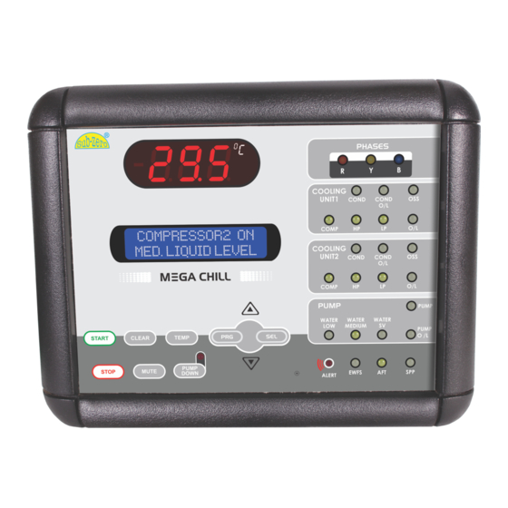
It is very user friendly due to the location of the sensor. LCD provided which gives all the Protection of the Mega Chill User Interface is a user friendly board which integrates all parameters, messages, alarms compressor with indication controller keys, display LCD and display LEDs. - Page 5 All manuals and user guides at all-guides.com 2 COMPRESSOR 2 COMPRESSOR Liquid Crystal Display (LCD) Light Emitting Diodes (LED) 3.2 Input/Output Board The LCD screen shows description There are 23 LED indications on The Relay board represents the On this board you can locate : of the controller parameters, and the chiller front panel indicating : core of the system, where the...
-
Page 6: Input/Output Board
223mm 243mm 3.4 Prokey This hardware key enables the manufacturer to enter programming Level 2(Factory Level Programming). Mega Chill User Interface Prokey (Only for equipment manufacturer) 3.5 Transformer System uses a highly reliable Toroidal transformer as it’s power supply source. -
Page 7: Connections
All manuals and user guides at all-guides.com 2 COMPRESSOR 2 COMPRESSOR 3.7 Connections Input/Output Board FUSE WATER SV B PHASE Y PHASE FUSE R PHASE PUMP NEUTRAL FUSE PUMP O/L COND.2 EWFS FUSE 8 way LAN cable COND2 O/L COND1 O/L OSS2 COMP.2 COMP2 O/L... -
Page 8: Operations
2 COMPRESSOR 2 COMPRESSOR 4. Operations 4.2 Mega Chill Keypad 4.1 Description- Input /Outputs Analog Inputs (Probe) Mega chill manages the following The system has the following protections analog (probe) inputs. Digital Inputs (Trip Signals) 1. CONTROL - Used as the 1. -
Page 9: How To Turn On/Off The Chiller
All manuals and user guides at all-guides.com 2 COMPRESSOR 2 COMPRESSOR 1. START 4. MUTE 4.3 How to Turn ON/OFF the Chiller Press and hold this key for 4 Press this key for 1 second, to seconds to bring the controller in disable the buzzer and alarm relay. -
Page 10: Water Pump
WARNING If the machine controlled by mega chill is not using where he wants to regulate the water / media. the water level sensing feature, it is necessary to short all water inputs concerning the water level. -
Page 11: Programming
All manuals and user guides at all-guides.com 2 COMPRESSOR 2 COMPRESSOR 4) Press PRG to store the 5. PROGRAMMING modified parameters and return to the user parameters 5.1 Programming Levels menu. Program mode There are two programming levels allowing authorized personnel to main probe cal enter and change parameters LEVEL 1 - USER... -
Page 12: Factory Parameters
All manuals and user guides at all-guides.com 2 COMPRESSOR 2 COMPRESSOR 5.4 Parameter Description & Values 3) Using the UP and DOWN keys Para : Parameter M.U.: Measuring Unit MAX : Maximum settable Limit Set By : U = User, F = Factory min : time in minutes MIN : Minimum settable Limit allows scrolling all factory... - Page 13 All manuals and user guides at all-guides.com 2 COMPRESSOR 2 COMPRESSOR Para Description MIN MAX Fac. M.U. Var. Para Description MIN MAX Fac. M.U. Var. “FAN START LOGIC” Flag “MIN SET TEMP” A1+1 Lower Fan Start Logic Minimum Cooling Set-Point 0 = Fan always On.
-
Page 14: Alarms
All manuals and user guides at all-guides.com 2 COMPRESSOR 2 COMPRESSOR Para Description MIN MAX Fac. M.U. Var. Para Description MIN MAX Fac. M.U. Var. false alarm can be avoided “FAULT IN STANDBY” Flag due to low pressure at Compressor start up. It Enable/Disable fault sensing in standby mode. -
Page 15: Technical Specifications
9) I.P. Standards a) -30 C to + 50 C a) Probe - IP68 b) Mega Chill User Interface - 2) Digital Inputs CAUTION WARNING: If buzzer hole is sealed, rating...
Need help?
Do you have a question about the MEGA CHILL and is the answer not in the manual?
Questions and answers