
Related Manuals for Sub-Zero MEGA CHILL


Summary of Contents for Sub-Zero MEGA CHILL
- Page 1 Navi Mumbai, India Tel: 91-22-27782005 Fax: 91-2227782008 E-mail: info@pvrcontrols.com Web: www.pvrcontrols.com...
-
Page 2: Table Of Contents
CONTENTS Introduction 1.1 Main Features 1.2 Hardware Description Hardware Mega Chill User Interface Input/Output Board Sensors Prokey Transformer Dimensions Connections Operations Description - Inputs / Outputs Mega Chill Keypad How to Turn On/Off the Chiller Water Pump Water Temperature Set-Point and Differential... -
Page 3: Introduction
The manufacturer is not ‘user interface’ for an easy WATER condensation. liable for incorrect use/misuse of the product mentioned. communication between user and AIR condensation. the controller. PVR Controls, All rights reserved Sub-Zero and the Sub-Zero logo are registered trademarks of PVR Controls. -
Page 4: Hardware
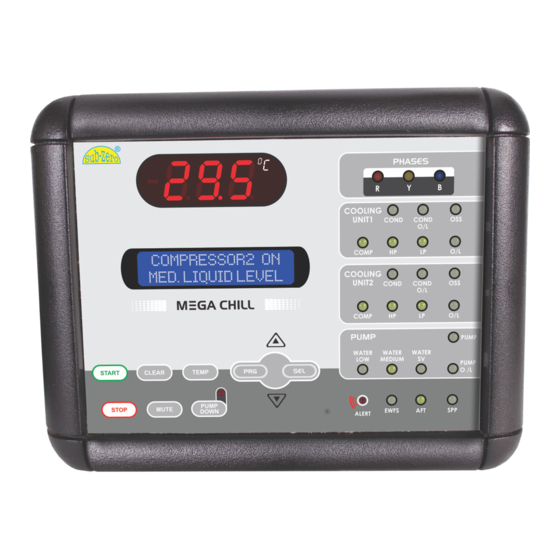
Device OK status - Green LED 2.1 Mega Chill User Interface Liquid Crystal Display (LCD) indicates that the device is OK. Mega Chill User Interface is a user friendly board which integrates all controller keys, display LCD and display LEDs. Light Emitting Diodes (LED) -
Page 5: Input/Output Board
2.3 Sensors 2.2 Input/Output Board Japanese NTC thermistors, housed in a water proof I.P. 68 metal The Relay board represents the On this board you can locate : casing. core of the system, where the 1. Terminals for power source- signals coming from the probes, 10Vac (yellow) &... -
Page 6: Dimensions
2.6 Dimensions 2.7 Connections Input / Output Board MGC-1COMP-RLY MGC-1COMP-RLY Mega Chill User Interface 6 way telephone cable Chiller Interface Terminal for panel mounting Panel cutout 124 mm X 167 mm (All dimensions in mm) -
Page 7: Operations
3. Operations Input/Output Board 3.1 Description - Input / Mega chill manages the following Outputs Analog Inputs (Probe) protections The system has the following Digital Inputs (Trip Signals) analog (probe) inputs. 1. CONTROL - Used as the 1. HP - High Pressure main controlling probe based 2. -
Page 8: Mega Chill Keypad
‘TEMP’ key once. 2. STOP Stops the system and brings TEMP Mega Chill back to a standby status. 3. COMP RESET In case of an internal compressor The LCD will display the probe reset for example in Bitzer l o c a t i o n a n d i t ’... -
Page 9: How To Turn On/Off The Chiller
3.3 How to Turn ON/OFF the Chiller 3.4 Water Pump 3.6 Set-Point and Differential PUMP is the first device to be Set point is the temperature at activated after the chiller has which the chiller has to be started. Pump functioning has regulated. -
Page 10: Pump-Down
UP WARNING and DOWN key. If the machine controlled by mega chill is not using the water level sensing feature, it is necessary to short all water inputs concerning the water level. This will disable the liquid level errors. -
Page 11: Factory Parameters
4) Press PRG to store the 4) Using the UP and DOWN keys modified parameters and allows scrolling all factory return to the user parameters parameters. menu. 4) Press SEL display the required factory parameter. 5) To end programming and exit user mode, press SEL key when LED display shows EP. -
Page 12: Parameter Description & Values
4.4 Parameter Description & Values Para : Parameter M.U.: Measuring Unit MAX : Maximum settable Limit Set By : U = User, F = Factory mini : time in minutes MIN : Minimum settable Limit Fac. : Factory set values Sec : time in seconds Var : Variation C : Temperature in degree centigrade... -
Page 13: Alarms
Para Description MIN MAX Fac. M.U. Var. Para Description MIN MAX Fac. M.U. Var. Pump Lock Flag 0 = Inactive Differential for AFT Probe 1 = Active. In this case pump down will Flow Switch Alarm Sec. perform every time the Delayed at Power On compressor cuts off and also If this parameter is set at 30... -
Page 14: Technical Specifications
Probe - Ip68 2) Digital Inputs b) Mega Chill User Interface - influences, which may affect the (Potential Free Contacts) buzzer hole is sealed, temperature to be controlled.
Need help?
Do you have a question about the MEGA CHILL and is the answer not in the manual?
Questions and answers