Advertisement
Quick Links
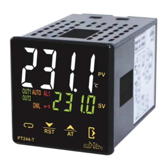
PT244-T / PT244-K / PT244-T-AA
Operating Manual
Introduction
A proportional–integral–derivative controller (PID controller or three
term controller) is a control loop feedback mechanism widely used in
industrial control systems and a variety of other applications requiring
continuously modulated control. A PID controller continuously
calculates an error value as the difference between a desired
setpoint (SV) and a measured process variable (PV) and applies a
correction based on proportional, integral, and derivative terms
(denoted P, I, and D respectively) which give the controller its name.
PT244-T is a two set point PID controller. It is available in touch &
keypad version. Customized iconic display interprets status easily.
Caution for your safety
WIRING: The probe and its corresponding wires should never be
installed in a conduit next to control or power supply lines. The
electrical wiring should be done as shown in the diagram. The
power supply circuit should be connected to a protection switch.
The terminals admit wires of upto 2.5sq mm.
WARNING: Improper wiring may cause irreparable damage and
personal injury. Kindly ensure that wiring is done by qualified
personnel only.
Maintenance: Cleaning: Clean the surface of the controller with a
soft moist cloth. Do not use abrasive detergents, petrol, alcohol or
solvents.
Notice: The information in this document is subject to change in
order to improve reliability , design or function without prior notice
and does not represent a commitment on the part of the company.
In no event will the company be liable for direct, indirect, special,
incidental or consequential damage arising out of the use or
inability to use the product or documentation, even if advised of
the possibility of such damages. No part of this manual may be
reproduced or transmitted in any form or by any means without
the prior written permission of the company.
Controller :Controller should be installed in a place
protected by vibration, water and corrosive gasses and
where ambient temperature does not exceed the values
specified in the technical data.
Probe :To give a correct reading, the probe must be installed
in a place protected from thermal influences, which may
affect the temperature to be controlled.
Dimensions
48mm
PV
48mm
SV
PT244-T
Panel Cutout
45.5mm
45.5mm
Product Mounting
Installation : Fixing and dimensions of panel models:
To fix the unit, slide the fastener 1 through the guides 2 as per the
position shown in the figure. Move the fastener in the direction of the
arrow, pressing tab 3 it permits to move the fastener in the opposite
direction of the arrow.
2
1
3
48mm
PANEL
Side Lock
GASKET
CONTROLLER
Connection Diagram ( for PT244-T-
W2C30
P
1
11
6
RTD1
230V
+
N
SSR
2
7
-
RTD2
TC
NO1
+
3
8
RTD3
C1
4
SSR
NC1
5
12
Connection Diagram ( for PT244-T-
P
1
11
6
230V
+
SSR
N
2
7
-
TC
+
8
NO
4
SSR -
5
12
C
Connection Diagram ( for PT244-T/K-W2C34 )
P
1
11
6
230V
SSR +
N
2
7
-
TC
NO1
+
3
8
4
-
C1
SSR
5
12
10
NO2
C2
Connection Diagram ( for PT244-T/K-W*C34 )
+
1
11
6
Power
*
Supply
-
SSR +
2
7
-
TC
NO1
+
3
8
4
-
C1
SSR
5
12
10
NO2
C2
*
12Vac/dc or 24V ac/dc on request
Index
Sr.
Description
Para.
No.
User Interface
Technical Specification
Input types & Input range
Working
Initial display when Power is ON
Parameter setting mode
Set mode
Control1 set point.
1
2
Control2 set point.
3
Sets the dwell time.
Level1 Parameter
4
Sets the type of input sensor .
5
Sets input correction.
6
Sets the lower limit of PV input.
7
Sets the upper limit of PV input.
8
To enable Dwell timer.
High temperature limit. (for 1 Relay)
9
10
Low temperature limit. (for 1 Relay)
Sets control action for relay2. (for 2 Relay)
11
12
Sets the hysteresis2. (for 2 Relay)
13
Sets the alarm type. (for 2 Relay)
Sets AL1 icon as alarm relay. (for 2 Relay)
14
15
Factory reset parameter.
Level2 Parameter
Sets control action for relay1 / SSR.
16
17
Runs auto tuning.
18
Sets cycle time for PID action.
Sets proportional band.
19
Sets integration time.
20
Sets differential time.
21
Sets the
hysteresis
1
22
Sets Control1 output.
23
24
Lock keypad.
Alarm Types
LED Indications
Error Messages
Pro-key (On-request)
Ordering Information
User Interface
6
7
4
5
8
9
PT244-T
)
10
11
12
13
Sr.
Description
No.
Process Value (PV)
1
RUN mode : Displays current measured value.
SETTING mode : Displays parameter.
2
Set value (SV)
RUN mode : Displays set value.
Displays countdown time when Dwell timer is
running.
SETTING mode : Displays set value of parameter.
3
Displays the Temperature unit.
4
Turns ON while control output1 is ON.
W2C30
AA )
Turns ON while control output2 is ON. (for two relay)
5
Turns ON when the corresponding alarm out turns
6
ON.
RTD1
7
Turns ON when auto tuning is in progress.
RTD2
Flashes during Dwell timer is in progress.
8
Continuous ON : Dwell time elapsed.
Turns ON when keypad is locked.
9
RTD3
10
Next key :
Used to enters parameters level, moves to next
parameters.
Press & hold this key atleast 2 seconds to enter
in set mode.
Press & hold this key atleast 4 seconds to enter
in Level1 Parameters.
Press & hold this key atleast 6 seconds to enter
in Level2 Parameters.
Down
/ Reset Key :
11
Used in Program mode to decrement parameter
RTD1
value.
Used to reset the Dwell timer..
RTD2
Up / AT Key :
12
Used in Program mode to increment parameter
value.
RTD3
Press this key for 2 seconds to start or stop auto-
tuning.
Exit Key :
13
Press this key to save the setting value and to exit
the programing mode.
Model Description
1. PT244-T-W2C34 / PT244-K-W2C34 - Two Relay
2. PT244-T-W2C30AA - Single Relay
3. PT244-T-W2C30 / PT244-K-W2C30 - Single Relay
4. PT244-T-W5C34 / PT244-K-W5C34 - Two Relay
RTD1
Technical Specification
RTD2
Housing
: Polycarbonate Plastic
Dimensions
: Frontal : 48 X 48mm, Depth : 78mm
RTD3
Panel Cutout
: 45.5 X 45.5mm
Mounting
: Flush panel mounting with fasteners.
Protection
: IP65 Front
Connections
: Terminal connectors.
< 2.5sq mm terminal only.
Display
: 4 X 17mm 7 segment Red/White display,
4 X 8mm 7 segment Green display
7 Iconic LEDs for Indication
Data storage
: Non-volatile flash memory
Operating temp. : 0°C to 60°C (non-condensing)
Operating humidity : 20% to 85% (non-condensing)
Storage temp
: -25°C to 60°C (non-condensing)
Power input
: 230 Vac ±15 % , 50/60Hz Standard.
85 to 265Vac, 12/24Vdc on request.
Control output
: (For all PT244-T- / PT244-K)
Relay : 5A, 230V AC (Res.) or
SSR (field selectable) : 10V DC, 30mA
Except -
(For PT244-T-W2C30 / PT244-K-W2C30)
Relay : 10A, 230V AC (Res.) or
SSR (field selectable) : 10V DC, 30mA
(For PT244-T-W2C30AA)
Relay : 16A, 230V AC (Res.) or
SSR (field selectable) : 10V DC, 30mA
Auxiliary output : (For all PT244-T / PT244-K)
Relay : 5A, 230V AC (Res.)
Input Type
: RTD : Pt100
Thermocouple : J, K
Resolution
: 0.1 C / 1 C for RTD (Pt100) input
O
1 C for Thermocouple (J, K) input
O
Display Accuracy: RTD : 0.1% of F.S +/- 1 C
Thermocouple : 0.3% of F.S
(20 min of settling time for TC)
Sampling Period : 1 second
Input types & Input range
Decimal
Input Type
Point
J
Thermocouple
K
Pt
RTD
100
Working
1. Auto tuning
The Auto-tuning function automatically computes and sets the
proportional band (P), Integral time (I), Derivative time (D) as
per process characteristics.
While Auto-tune is in progress "AUTO" led will turn ON.
After Auto-tuning is complete the "AUTO" led will turn OFF.
PID-time proportional
with auto reset & rate
PV
1
If auto -tuning is not complete after 3-4 cycles, it is suspected to
3
fail. In this case, check the wiring & parameters such as the
control action, input type etc.
2
SV
Carry out the auto-tuning again, if there is a change in setpoint
or process parameters.
Note : In Auto Tuning running time, user can not change
the parameter value.
2. ON/OFF control action (For reverse mode)
The relay is 'ON' up to the set temperature and cuts"OFF"
above the set temperature . As the temperature of the system
drops ,the relay is switched 'ON' at a temperature lower than
the set point .
HYSTERESIS:
The difference between the temperature at which relay
switches 'OFF' is the hysteresis or dead band.
3. Dwell Timer :
A dwell timer is used to control a process at a fixed temperature
for a defined period. Once the process reaches the setpoint,
dwell timer starts to count until time out . After the time
completes, control output goes OFF and auxiliary output
energises as an alarm.
Note:
1) Countdown timer is displayed on the lower display. Once
total time elapsed lower display will show "
(Not applicable for PT244-K)
2) DWL icon LED blinking indicates that dwell timer is in
progress. It switches to continuous 'ON' when dwell
timer is over.
3) If Dwell time programmed as OFF, it will disable the dwell
timer.
4) When soak in progress & dwell time is modified, new
dwell time is applicable .
5) The dwell period can be reduced or increased when the
timer is running. if it is reduced to meet the time elapsed.
the timer will change to the end state.
6) Once the timer output was energized it can be reset with
the
Initial Display when Power is ON
When power is On, entire display part will flash for
3 sec, software version will flash for 3 sec and then enter in to
RUN mode.
1. Entire display Part
Parameter Setting Mode
1
Parameter
Display will show
UP/ DOWN keys. Holding the key, will change the value at a
faster rate. Press
on to the next parameter.( For 2 relays
value also can be stored by pressing
2
O
Parameter
O
This parameter is prompted only if Relay 2 is configured in
,
1. As absolute auxiliary control or as an alarm (High/Low)
mode.
2. As deviation auxiliary control or as a deviation alarm mode.
Note: If
Display
Input Range ( C)
O
setting.
1
-50 to 750 C
O
1
-50 to 1200 C
O
3
1
-99 to 400 C
O
0.1
-99.9 to 400.0 C
O
Parameter
This parameter is prompted only if Relay 2 is configured in
as "
This parameter is prompted only if
configured as
For dwell timer operation please refer Working section.
Press & hold
parameter setting(
When release the key,
Press UP/DOWN keys to modify the set value and to go to the
next parameter by pressing
Press the
parameter setting after changing the set value.
4
Parameter
While changing the sensor type
,
For type of input sensor & range please refer "Input types
& Input range" table.
5
Parameter
In time it may be possible that the display may be offset by a
degree or so.
To compensate for this error, user may need to add or minus
the degrees required to achieve the correct temperature.
Example : The temperature on the display is 28 C, whereas
the actual temperature is 30 C. User will have to set the "
parameter to 2 C, which means that once out of the
programming mode, the temperature on display will be 30 C
(28 C+ 2 C).
O
O
Settings
=
=
min
10min
".
Reset key.
2. Run Mode
SET MODE
Function: To set control1 set point.
Press & hold
key for 2 second.
.
User can change
value using
key to store the desired value & move
/ Dwell). Set
Key
Min
Max
Fac.
0 C
O
Function: To set control2 set point.
(For 2 Relays)
set to OFF,
will not be shown in the SP
Min
Max
Fac.
0 C
O
Function: Sets the dwell time.
".
parameter in
is
. (Only for Single Relay)
Min
Max
Fac.
9999
min
LEVEL1 Parameter
key for 4 seconds to enter into Level1
will flash).
will flash.
key.
key to save the set value and to come out of
Function: Sets the type of input sensor .
,
,
,
,
,
parameters of level1 will reset accordingly.
For J type sensor
Min
Max
Fac.
Function: Sets input correction.
O
O
"
O
O
Min
Max
Fac.
-20 C
O
20 C
O
0 C
O
Advertisement

Related Manuals for Sub-Zero PT244-T


Summary of Contents for Sub-Zero PT244-T
- Page 1 (Not applicable for PT244-K) Up / AT Key : PT244-T is a two set point PID controller. It is available in touch & 2) DWL icon LED blinking indicates that dwell timer is in Used in Program mode to increment parameter keypad version.
- Page 2 Function: Sets the lower limit of PV input. Function: Runs auto tuning. LED Indication Calibration Certificate Parameter Parameter Status Description DATE This parameter is used to set YES/NO to start and stop Auto- Sets the minimum limit for set point adjustment. It can be set Relay1 / SSR ON.
Need help?
Do you have a question about the PT244-T and is the answer not in the manual?
Questions and answers