Table of Contents
Advertisement
Available languages
Available languages
Quick Links
Advertisement
Chapters
Table of Contents

Related Manuals for PROEL LTX12A


Summary of Contents for PROEL LTX12A
- Page 1 USER’S MANUAL ENGLISH ITALIANO 96MAN0173-REV.29/23...
-
Page 3: Table Of Contents
INDEX IMPORTANT SAFETY INSTRUCTIONS ....................4 FEDERAL COMMUNICATIONS COMMISSION (FCC) STATEMENT ............5 DECLARATION OF CONFORMITY ....................5 LIMITED WARRANTY ........................5 CONDITIONS OF USE ........................5 INTRODUCTION..........................6 DESCRIPTION ..........................6 MAIN PANEL OPERATIONS ......................6 KPTLTP BRACKET ASSEMBLY INSTRUCTIONS .................. 8 KPTLTX12 BRACKET ASSEMBLY INSTRUCTIONS ................ -
Page 4: Important Safety Instructions
IMPORTANT SAFETY INSTRUCTIONS Watch for these symbols: The lightning flash with arrowhead symbol within an equilateral triangle is intended to alert the user to • the presence of uninsulated “dangerous voltage” within the product’s enclosure, that may be of sufficient magnitude to constitute a risk of electric shock to persons. -
Page 5: Federal Communications Commission (Fcc) Statement
This warranty does not extend to damage resulting from improper installation, misuse, neglect or abuse. Proel S.p.A. will verify damage on returned units, and when the unit has been properly used and warranty is still valid, then the unit will be replaced or repaired. -
Page 6: Introduction
INTRODUCTION Thank you for choosing a PROEL product. Please take some time to read this manual to understand all the features of your system and take advantage of all its performance capabilities. All PROEL products are CE approved and designed for continuous use in professional applications. - Page 7 SIGN/LIMIT INDICATOR GREEN LED indicates the presence of the signal at the amplifier input. RED LED illuminates when the internal amplifier's output is limited. When this LED flashes continuously reduce the input signal level. ON INDICATOR GREEN LED: when lighted indicates that the amplifier has been turned on and AC power is available. M6 FIXINGS These two fixings points is where to fix the KPTLTP bracket.
-
Page 8: Kptltp Bracket Assembly Instructions
AC~ SOCKET This is where the mains power cord plugs in. Always use the power cord supplied with the device. Make sure your device is turned off before plugging or unplugging the power cord. The connector is equipped with a locking system: insert it and rotate it clockwise until the lock clicks. To disconnect the plug, push the lock back and rotate the plug counter-clockwise. - Page 9 Mount the KPTLTP on the wall considering the required free space around it for proper aiming of the • speaker as shown in FIG.1. • Fix the wall plate on the wall using a proper fixing plug and screw (not supplied) capable to carry ten times the weight of the speaker and its support.
- Page 10 FIG.8 and FIG.9 show the possible vertical tilting combinations: FIG.8 is for the speaker mounted • vertically or FIG.9 for speaker mounted horizontally. • FIG.10 and FIG11 show the possible horizontal swivel combinations: FIG.10 is for the speaker mounted vertically or FIG.11 for speaker mounted horizontally.
-
Page 11: Kptltx12 Bracket Assembly Instructions
KPTLTX12 BRACKET ASSEMBLY INSTRUCTIONS Remove the feet under the speaker box using a Phillips screwdriver to unscrew the 4 screws (FIG.12). • • Put the screws back in their positions (FIG.13). • Remove the two M8 screws on top and bottom of the speaker (FIG.14). •... - Page 12 Fix the speaker to the bracket using the supplied washers and screws at both sides. The rubber • washer (6) must be placed between the bracket leg and the speaker, the metal washer (7) must be placed outside the bracket leg. Use the screws (8) to fix the bracket to the speaker, aim the speaker and tight the screws (FIG.16).
-
Page 13: Connection Example
CONNECTION EXAMPLE IMPORTANT: always use balanced audio connections for long lines. -
Page 14: Optional Accessories
Other accessories are available for temporary or fixed installations: SPEAKER FLOOR STAND • FRE300K – aluminium black stand (FRE300KIT dual with bag). TECHNICAL SPECIFICATIONS LTX12A System type 2-way vented enclosure High Frequency Device 1’’ compression driver with 1" voice coil Low Frequency Device 12"... - Page 15 INDICE ISTRUZIONI DI SICUREZZA IMPORTANTI ..................16 DICHIARAZIONE DI CONFORMITÀ ....................17 GARANZIA LIMITATA ........................17 CONDIZIONI D'USO ........................17 INTRODUZIONE ........................... 18 DESCRIZIONE ..........................18 FUNZIONI DEL PANNELLO PRINCIPALE ..................18 ISTRUZIONI DI MONTAGGIO DELLA STAFFA KPTLTP ..............20 ISTRUZIONI DI MONTAGGIO DELLA STAFFA KPTLTX12 ..............
-
Page 16: Istruzioni Di Sicurezza Importanti
ISTRUZIONI DI SICUREZZA IMPORTANTI Guarda questi simboli: Il lampo con la freccia all'interno di un triangolo equilatero ha lo scopo di avvisare l'utente della presenza di • "tensione pericolosa" non isolata all'interno della custodia del prodotto, che può essere di ampiezza sufficiente a costituire un rischio di scossa elettrica per le persone. -
Page 17: Dichiarazione Di Conformità
GARANZIA LIMITATA Proel garantisce tutti i materiali, la lavorazione e il corretto funzionamento di questo prodotto per un periodo di due anni dalla data di acquisto originale. I difetti rilevati entro il periodo di garanzia sui prodotti venduti, attribuibili a materiali difettosi o difetti di costruzione, devono essere tempestivamente segnalati al proprio rivenditore o distributore, allegando evidenza scritta della data di acquisto e descrizione del tipo di difetto riscontrato. -
Page 18: Introduzione
Switch Mode e l'amplificatore in CLASSE D per i bassi e l'amplificatore in CLASSE AB per gli alti, ed è in grado di fornire una grande quantità di potenza in un peso ridotto. LTX12A include una sofisticata sezione di pre-amplificazione, con filtri crossover allineati in fase e tagli fino a 24 dB/ott. e con filtri EQ attivi per la regolazione fine del sistema. - Page 19 L'attenuazione va da “0” completamente chiuso (il segnale è completamente attenuato) a “10” completamente aperto (il segnale è al livello nominale). Questo controllo non influisce sul segnale che passa attraverso il connettore LINK. 4. INDICATORE SEGNALE/LIMITER Il LED VERDE indica la presenza del segnale all'ingresso dell'amplificatore. Il LED ROSSO si accende quando l'uscita dell'amplificatore interno è...
-
Page 20: Istruzioni Di Montaggio Della Staffa Kptltp
FISSAGGI M6 Questi due punti di fissaggio sono dove fissare la staffa KPTLTP. AC~ SOCKET Inserire in questa presa il cavo di alimentazione di rete, utilizzando esclusivamente il cavo in dotazione. Accertarsi che il diffusore sia spento prima di collegarlo alla rete. Il connettore è dotato di un sistema di bloccaggio: inserirlo e ruotarlo in senso orario fino allo scatto del sistema di blocco. - Page 21 Montare il KPTLTP sulla parete tenendo conto dello spazio libero necessario attorno ad esso per un • corretto puntamento del diffusore come mostrato in FIG.1. • Fissare la piastra a muro alla parete utilizzando un apposito tassello e vite (non in dotazione) in grado di sostenere dieci volte il peso del diffusore e del suo supporto.
- Page 22 Le FIG.8 e FIG.9 mostrano le possibili combinazioni per orientare il diffusore sull’asse verticale: la • FIG.8 per il diffusore montato verticalmente, la FIG.9 per il diffusore montato orizzontalmente. • Le FIG.10 e FIG.11 mostrano il possibile orientamento del diffusore sull’asse orizzontale: la FIG.10 per il diffusore montato verticalmente, la FIG.10 per il diffusore montato orizzontalmente.
-
Page 23: Istruzioni Di Montaggio Della Staffa Kptltx12
ISTRUZIONI DI MONTAGGIO DELLA STAFFA KPTLTX12 Rimuovere i piedini sotto la cassa utilizzando un cacciavite a croce per svitare le 4 viti (FIG.12). • • Riavvitare le viti nelle proprie posizioni (FIG.13). • Rimuovere le due viti M8 sopra e sotto l'altoparlante (FIG.14). •... - Page 24 Fissare l'altoparlante alla staffa utilizzando le rondelle e le viti in dotazione su entrambi i lati. La • rondella in gomma (6) deve essere posizionata tra la gamba della staffa e l'altoparlante, la rondella metallica (7) deve essere posizionata all'esterno della gamba della staffa. Utilizzare le viti (8) per fissare la staffa al diffusore, puntare il diffusore e serrare le viti (FIG.16).
-
Page 25: Esempio Connessioni
ESEMPIO CONNESSIONI IMPORTANTE: utilizzare sempre connessioni audio bilanciate per le linee lunghe. -
Page 26: Accessori Opzionali
Altri accessori sono disponibili per installazioni temporanee o fisse: SUPPORTO DA PAVIMENTO PER ALTOPARLANTI • FRE300K – supporto in alluminio nero (FRE300KIT doppio con borsa). SPECIFICHE TECNICHE LTX12A Sistema 2-vie bass reflex Altoparlante per Alti Driver 1” a compressione con bobina da 25.4mm Altoparlante per Bassi Woofer 12"con bobina da 63.5mm... -
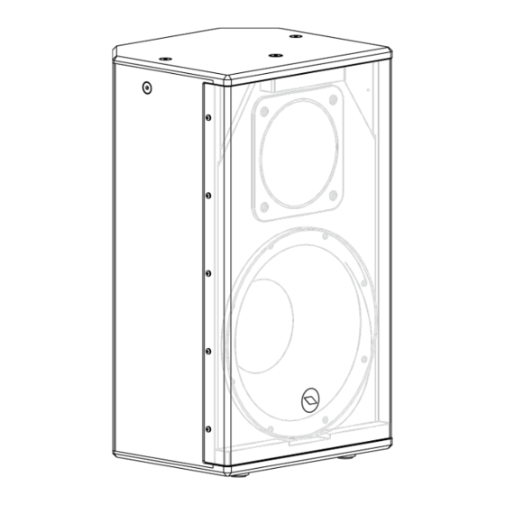
Page 27: Mechanical Drawing
MECHANICAL DRAWING / DISEGNO MECCANICO... - Page 28 PROEL S.p.A. (World Headquarters - Factory) Via alla Ruenia 37/43 64027 Sant’Omero (Te) – Italy Tel: +39 0861 81241 Fax: +39 0861 887862 www.proel.com...
Need help?
Do you have a question about the LTX12A and is the answer not in the manual?
Questions and answers