Table of Contents
Advertisement
Quick Links
Advertisement
Table of Contents

Related Manuals for Daruifuno MCC100


Summary of Contents for Daruifuno MCC100
- Page 1 Daruifuno Multi-parameter Controller User Manual Model:MCC100/200 Version 1.0...
- Page 3 Important Safety Information Please read and observe the following: Please read this entire manual before unpacking, installation and operation, with particular attention to all danger warnings and precautions. Failure to do so may result in damage to the instrument or personal injury to the operator due to misuse. Do not install or use the instrument by any means other than those specified in this manual.
- Page 4 Guarantee Our company warrants the instrument for one year (12 months) from the date of delivery. Consumables and consumable parts in the equipment are not covered by the warranty. The terms of this warranty shall not apply if damage to the instrument occurs beyond the warranty period, or in the opinion of the company, the breakage or destruction of the instrument is due to improper use, lack of maintenance, improper installation, improper modification, abnormal environmental conditions, etc.
-
Page 5: Table Of Contents
Contents Part 1 Introduction Chapter 1 Overview 1.1 Technical parameters ..........1 Part 2 Installation Chapter 2 Unpacking . - Page 6 7.4 Current set ..........12 7.4.1 Output type .
-
Page 7: Part 1 Introduction
Part 1 Introduction — — — Chapter 1 — — — Overview This product is a digital analytical instrument. According to the measurement object, it is connected to a digital electrode to measure various material parameters. The instrument supports two current outputs, one digital communication output and two control relays with configurable functions. -
Page 8: Part 2 Installation
Part 2 Installation — — — Chapter 2 — — — Unpacking After unpacking, it is recommended that the shipped cardboard boxes and packing materials be saved for instrument storage or reshipment. Inspect equipment and packing materials for signs of damage during shipment. If there are signs of damage, immediately notify the person delivering the shipment. -
Page 9: Dimension
3.2 Dimension Figure 3-1 Schematic diagram of the appearance and dimensions of the instrument 3.3 Panel mounting When the instrument is installed in the panel cabinet type, use two fixing brackets to fix the instrument. The installation diagram is as follows: Figure 3-2 Panel mounting - 3 -... -
Page 10: Wall Mounting
3.4 Wall mounting Connect the gray back panel to the instrument, and then install it on the box or the side wall of the wall. The installation dimensions and schematic diagram are as follows: Figure 3-3 Schematic diagram of wall-mounted installation Figure 3-4 Wall-mounted installation hole size diagram - 4 -... -
Page 11: Pipeline Mounting
3.5 Pipeline mounting Connect the gray backplane to the instrument, and then fix the backplane to the horizontal pipe or vertical pipe with a clamp. The installation diagram is as follows: - 5 -... -
Page 12: Chapter 4 Electrical Installation
— — — Chapter 4 — — — Electrical Installation 4.1 Power connection Two types of power supply: AC power supply 100 ~ 240VAC and DC power supply 18~36VDC. After unscrewing the screws at the back of the meter and taking off the cover, you can see two rows of terminals. -
Page 13: Wiring Terminals Definition
4.2 Wiring terminals The terminal locations and names are shown in Figure 4-2: Figure 4-2 terminal blocks The following table is the terminal definition: Current two output positive Electrode power-terminal OUT2 Current two output negative Electrode power + terminal Current one output positive Electrode communication terminal B OUT1 Current one output negative... -
Page 14: Part 3 Operation
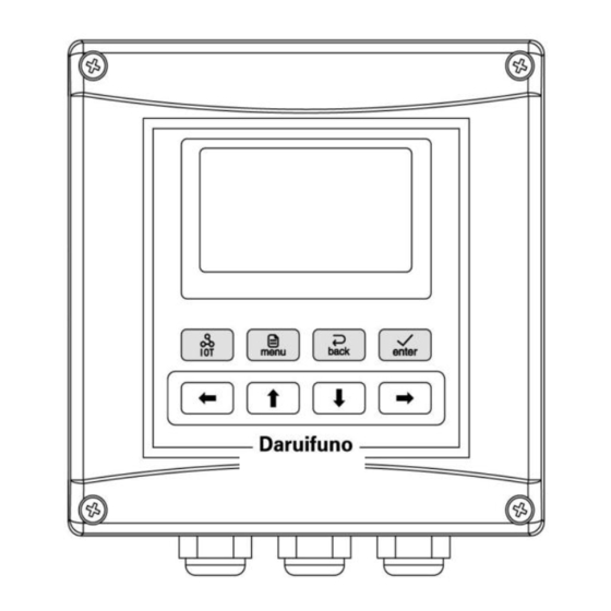
Part 3 Operation — — — Chapter 5 — — — User Interface The instrument panel consists of a display screen and four buttons, which are the MENU button, the ENTER button, and the down and the right direction button. As shown below: 5.1 Button Button Function... -
Page 15: Display
5.2 Display The meter normally displays the measurement interface after power-on. The specific information is as follows: Date Time Histogram Measured value Ambient temp warning Electrode type and connection status Date and time: Display current date and time information. Measured value: Display the current measurement value, the unit changes according to the measurement object. -
Page 16: Chapter 6 System Default Settings
— — — Chapter 6 — — — System Default Settings Setting type Setting Options Initial value Relay I Function Set Main Value Control Alarm Set Relay II Function Set Main Value Control Current I Output Type 4-20mA Current Set Current II Output Type 4-20mA... -
Page 17: Chapter 7 Menu Description
Chapter 7 — — — — — — Menu Description In the measurement interface, long press the MENU button to enter the menu. The following is a detailed introduction to the menu content. 7.1 Probe set According to the measurement object, the meter is connected to different electrodes, and the menu items are set according to the electrode type. -
Page 18: Cleaning Output
7.3.2 Cleaning output When selecting “Cleaning Output” in “Main Menu” -> “Alarm Set” -> “Relay X” -> “Function Set” menu , the relay is in the cleaning output state, the relay can be closed periodically to do cleaning control. 7.3.3 Cleaning state Select the state of the measured value during cleaning. - Page 19 7.4.1 Output type The output current type can be selected as “4-20mA” or “0-20mA”. 7.4.2 Channel selection The measurement value corresponding to the current can be specified as the “main measurement channel” or “temperature channel”. 7.4.3 Upper value Specify the measured value corresponding to the maximum output current. 7.4.4 Lower value Specify the measured value corresponding to the minimum output current.
- Page 20 7.7 Test maintenance 7.7.1 Current CAL To calibrate the current output value, take calibrating current 1 20mA as an example, first connect the ammeter to the current 1 output terminal, then enter the menu “Test Maintenance” -> “Current Cal” -> “Current 1 “ -> “Calibrate 20mA”. Press the key to increase or decrease the value displayed on the screen until the ammeter reads 20mA, then press the key to save the calibration result.
- Page 21 Part 4 Maintenance — — — Chapter 8 — — — General Remarks 8.1 Clean the controller 1. Make sure the controller cover is closed tightly. 2. Wipe the outside of the controller with a cloth dampened with water or a mixture of water and mild detergent.
- Page 22 Appendix A Modbus register information 1. Modbus RTU Overview: The instrument acts as a slave on the network and supports Modbus RTU communication protocol. Data communication is initiated by the host, and the first byte of the transmitted message is the target slave address.
- Page 23 For example: Send frame: [01 04 00 00 00 02 71 CB], the meaning is as follows: [01]: Instrument address [04]: Function code [00 00]: The starting register address is 0x0000 [00 02]: Read 2 registers starting from the starting address (that is, read 1 single-precision floating-point data result) [71 CB]: CRC check data Return frame: [01 04 04 CC CD 41 48 65 4D], the meaning is as follows:...
- Page 24 Suzhou Delfino Environmental Technology CO., Ltd www.daruifuno.com info@daruifuno.com...
Need help?
Do you have a question about the MCC100 and is the answer not in the manual?
Questions and answers