
Related Manuals for Daruifuno MCC200


Summary of Contents for Daruifuno MCC200
- Page 1 Daruifuno Digital Multi-parameter controller User Manual Model: MCC200 Version 1.0...
- Page 3 Important Safety Information Please read and observe the following: Please read this entire manual before unpacking, installation and operation, with particular attention to all danger warnings and precautions. Failure to do so may result in damage to the instrument or personal injury to the operator due to misuse. Do not install or use the instrument by any means other than those specified in this manual.
- Page 4 Guarantee Our company warrants the instrument for one year (12 months) from the date of delivery. Consumables and consumable parts in the equipment are not covered by the warranty. The terms of this warranty shall not apply if damage to the instrument occurs beyond the warranty period, or in the opinion of the company, the breakage or destruction of the instrument is due to improper use, lack of maintenance, improper installation, improper modification, abnormal environmental conditions, etc.
-
Page 5: Table Of Contents
Contents Part 1 Introduction Chapter 1 Overview 1.1 Technical Parameters ..........1 Part 2 Installation Chapter 2 Unpacking. - Page 6 7.5 System Set ........... . . 12 7.5.1 Data/Time set .
-
Page 7: Part 1 Introduction
Part 1 Introduction — — — Chapter 1 — — — Overview This product is a 4-channel digital universal controller, which realizes measurement by connecting various types of digital sensors for detecting physical, chemical and biological properties. 1.1 Technical Parameters Channels Quantity Control Type Wash relay... -
Page 8: Part 2 Installation
Part 2 Installation — — — Chapter 2 — — — Unpacking After unpacking, it is recommended that the shipped cardboard boxes and packing materials be saved for instrument storage or reshipment. Inspect equipment and packing materials for signs of damage during shipment. If there are signs of damage, immediately notify the person delivering the shipment. -
Page 9: Dimension
3.2 Dimension Figure 3-1 Schematic diagram of the appearance and dimensions 3.3 Panel mounting When the instrument is installed in a panel cabinet, use two fixing brackets to fix the instrument. The installation diagram is as follows: Figure 3-2 Panel mounting... -
Page 10: Mounting
3.4 Wall Mounting Connect the gray back panel to the instrument, and then install it on the box or the side wall of the wall. The installation dimensions and schematic diagram are as follows: Figure 3-3 Schematic diagram of wall-mounted installation Figure 3-4 Wall-mounted installation hole size diagram... -
Page 11: Mounting
3.5 Pipe mounting Connect the gray backplane to the instrument, and then fix the backplane to the horizontal pipe or vertical pipe with a clamp. The installation diagram is as follows: Figure 3-5 Schematic diagram of pipeline installation... -
Page 12: Power Connection
— — — Chapter 4 — — — Electrical Installation 4.1 Power Connection Two types of power supply: AC power supply 100~240VAC and DC power supply 18~ 36VDC. After unscrewing the screws at the back of the meter and taking off the cover, you can see two rows of terminals. -
Page 13: Wiring Terminals Definition
Two kinds of power terminals are defined in Table 4-1: AC power fire wire input DC power positive POWER POWER AC power ground wire Floating terminal AC IN DC IN 100-240V 18-36V AC power zero line input DC power negative 4.2 Wiring Terminals Definition The terminal locations and names are shown in Figure 4-2: Figure 4-2 terminal blocks... -
Page 14: Part 3 Operation
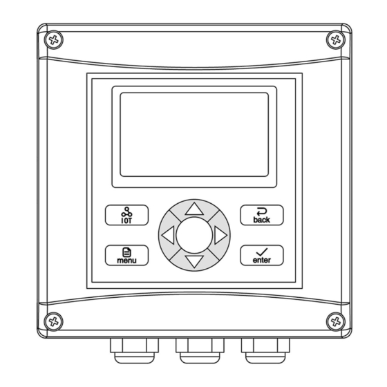
Part 3 Operation — — — Chapter 5 — — — User Interface The instrument panel consists of a display screen and eight buttons, namely IOT (Internet of Things) button, menu (menu) button, back (return) button, enter (confirm) button, four up, down, left and right Arrow keys. -
Page 15: Display
Menu button: In the measurement interface, enter the menu interface. In the menu option interface, directly return to the measurement state. In the parameter set interface, return to the previous menu. Enter button: In the menu option interface, select the selected item. In the parameter set interface, confirm and return to the previous menu. - Page 16 — — — Chapter 6 — — — System Default Settings Setting Type Setting Options Initial Value Clean interval 5min Wash Relay Duration of clean 60sec Wash state Hold Net address Baud Rate 9600bps Verify Bit None Comm. Set Stop Bit 1 bit Format CDAB...
-
Page 17: Chapter 7 Menu Description
— — — Chapter 7 — — — Menu Description In the measurement interface, long press the button to enter the menu. The following is a detailed introduction to the menu content. 7.1 Probe Set 7.1.1 Scan probe The initial state of the meter is no measurement value display. After connecting the probes, you need to scan the probes first, and then the corresponding measurement value can be displayed. -
Page 18: Alarm Relay
7.2.2 Alarm relay The relay is used for alarm control and can only be used after installing an external expansion module. 7.3 Current set To set the current signal output, it can only be used after installing an external expansion module. 7.4 Comm.set The instrument provides a digital communication interface, and this menu can set the parameters of the communication interface. -
Page 19: History Logs
7.6 History logs 7.6.1 Memory inform View meter history storage information. 7.6.2 Set interval Set the interval time for the instrument to record the measurement data, the setting range is 0~999min. When the recording interval is set to 0, it means that the recording function is turned off. -
Page 20: Information
Appendix A Modbus register information 1. About Modbus RTU overview: The instrument acts as a slave on the network and supports Modbus RTU communication protocol. Data communication is initiated by the host, and the first byte of the transmitted message is the target slave address. When the first byte is received by all the slaves on the network, each slave will decode it to determine whether the message is sent to itself. - Page 21 Slave response: 5+n+1 5+n+2 5+n+3 Device Function Data 1 Data n Data n Length Data 1 CRC high Address code low 8 bit high 8 bit low 8 bit high 8 bit low 8 bit 8 bit Addr Le n ☞...
-
Page 22: Diagram
Menu structure diagram... - Page 24 Suzhou Delfino Environmental Technology CO., Ltd www.daruifuno.com info@daruifuno.com...
Need help?
Do you have a question about the MCC200 and is the answer not in the manual?
Questions and answers