Table of Contents
Advertisement
Quick Links
Hybrid Industrial Gateways
Industrial communication Gateways with external power supply or battery.
Model
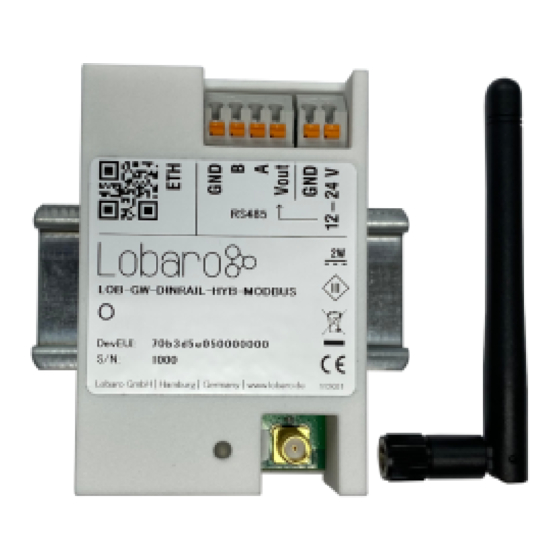
LOB-GW-DINRAIL-HYB-MODBUS
Order number
8000171 - Hybrid Gateway V2 (Battery)
8000159 - Hybrid Gateway (ext. Power, DIN-Rail)
8000166
8000200 - Hybrid Gateway (ext. Power, 230V) + 20x wired M-BUS Converter
Support for:
Modbus ASCII, RTU (RS-485) (all variants)
Wireless M-BUS (all variants)
Wired M-BUS (#8000200 only)
Modbus TCP/IP (Future Firmware on #8000159, #
Data communication using:
LTE-M
(all variants)
NB-IoT
(all variants)
LoRaWAN
(all variants)
LAN (#8000159,
#8000166, #8000200)
Current Limitations
The current firmware has some limitations. These features will be implemented in a future
release and do not work yet.
The firmware does not support Modbus over TCP, yet.
Modbus Downlinks are currently
with LoRaWAN.
8000159 - Hybrid Gateway (ext. Power, Din-Rail)
Including: Antenna
- Hybrid Gateway (ext. Power, 230V)
8000166
not
supported with LTE-M / NB-IoT - works only
)
8000166
- Hybrid Gateway (ext. Power, 230V)
Including: Antenna, 2x cable feedthrough
Table of Contents
Setting up the device (Din-Rail
variants)
Mobile operator and
LTE band
configuration
Networking
Parameters (NB-IoT /
LoRaWAN)
Parameters
Wireless M-Bus
related Parameters
Parameters
Modes of operation (work
cycle)
scan"
Upload type "mbus"
Status Message (Up,
Port 64)
different formats
to 5)
to 59)
Wireless M-Bus (Up,
Port 102)
Wired M-Bus (Up,
Ports 110 and 112)
Remote
Configuration (Down
& Up, Ports 128 to
131)
Format (PlFmt=1)
Downlink Commands
Payload Format
Advertisement
Table of Contents

Related Manuals for Lobaro LOB-GW-DINRAIL-HYB-MODBUS


Summary of Contents for Lobaro LOB-GW-DINRAIL-HYB-MODBUS
-
Page 1: Table Of Contents
LED patterns Data communication using: DIN-Rail Variant Battery Variant LTE-M (all variants) NB-IoT / LTE-M NB-IoT (all variants) The Lobaro Platform LoRaWAN (all variants) Envelope LAN (#8000159, #8000166, #8000200) Upload type "device" Upload type "config" Upload type "status" Current Limitations Upload type "modbus"... -
Page 2: Quick Start Guide
CatM1, LoRaWAN or LAN. Modbus commands can be transmitted via Downlink message to the Gateway and are forwarded by the Bridge to the connected Slave Devices. Received responses are forwarded as Uplink messages to the Lobaro IoT Platform. The Modbus Gateway can also be configured to execute Modbus commands regularly and report the responses at time of execution. -
Page 3: Modbus Introduction
Debugging a failing Modbus setup is quite complex, as there are many potential errors that cause the problems. Please also note that even when you succeed in reading the data you need from the correct registers, neither the Gateway, nor the Lobaro Platform can know, what that data means. - Page 4 SMA Joint Rod Antenna (LTE, LoRa) Frequency range 698-960 / 1710-2700 MHz Length 108 mm Antenna Gain 2 dBi V.S.W.R <= 2.5 Radiation Omnidirectional Polarisation Vertical Max. Power Impedance 50 Ohm Connector SMA Male Material of dome Lobaro Article No. 3000413...
-
Page 5: Configuration
LTE / NB-IoT Networks Configuration The device is shipped with default configuration parameters. The configuration can be changed via the 6-pin config port using the Lobaro USB Configuration Adapter. More information about the usage of the configuration tools can be found in our documentation Remote Configuration is also supported after initial network connection. - Page 6 Each Device will be configured with a unique JoinEUI and AppKey that are generated using a cryptographic hashing algorithm. Those values will seem random and are very likely to be unique for each device. These values are known to Lobaro but will not be made public. You can change the App if you prefere to have Keys that are known only to you.
-
Page 7: Parameters
Our devices support activation by personalisation (ABP) when . This mode is useful for devices that have a bad reception. You WAN="lorawan-abp" will have to synchronise session keys by hand between the device and your Network Server when using ABP. When using ABP, the device will use the parameters for generating the session parameters: DevEUI... - Page 8 Complete Syntax of MbCmd MbCmd = "<Entry1>;<Entry2>;...;<Entry32>" Entry = "<Cron>:<MbParm>:<Command1>,<Command2>,...,<CommandN>" MbParm = "<Protocol>,<Baud>,<SymbolCfg>" Protocol = "R" for Modbus RTC, "A" for Modbus ASCII Baud = Baud rate, any of: 2400, 4800, 9600, 19200, 38400, 57600, 115200 SymbolConfig = Token string defining Data Length, Parity, and Stop Bits. Any of: "7E1", "7E2", "8N1", "8N2" Command = "<bytes to be sent in hex without checksum>"...
-
Page 9: Wired M-Bus Related
Subject to change! Many feature of this device are still under development; wired M-Bus support is still experimental. When updating firmware, check the changelog for breaking changes. You need an M-Bus converter attached to the RS-485 connector of the Industrial Gateway to use wired M-Bus. Lobaro offers a complete solution including a converter under order number 8000200. -
Page 10: Startup Process
The starting process of the device is linear and executed the following steps in the order given here. The startup is triggered on power on or after a reset was triggered; this can happen over the reset button, by using the Lobaro tool over the config adapter, by sending a reboot command via Downlink, of if a fatal error occurs during operation of the device. -
Page 11: Battery Variant
The second flash indicates the state of the connection to the backend. This can be a connection to the Lobaro Platform via NB-IoT/LTE-M or Ethernet, or a LoRaWAN connection to a Network Server. -
Page 12: Envelope
Envelope Each uplink is enclosed in an envelope that contains 4 values: Uplink envelope "i": "70b3d5e050010001", "n": 19, "q": "...", "d": { ... } Meaning Explanation Identification The device's address (DevEUI), as printed on the device. A string. "i" Number Uplink Frame Counter, incementing number of uplink, starting with 1 on device boot. -
Page 13: Upload Type "Status
Payload for "config" uplink "SF": 12, "APN": "*", "DNS": "9.9.9.9,1.1.1.1", "PIN": "", "WAN": "nbiot", "Band": "", "Host": "coap://platform.lobaro.com", "PlId": 0, "MbCmd": "", "PlFmt": 1, "PlMax": 51, "AppKey": "ABCDEFGHIJKLB/Fqcg51iQ==", "DevEUI": "cLPV4FABAjM=", "OpMode": "A", "JoinEUI": "ABCDEFGsZeA=", "MbusCmd": "0 0 * * * *:R,9600,8N1:010300000003", "mFilter": "",... -
Page 14: Upload Type "Modbus
Upload type "modbus" The "modbus" uplink is sent for each entry in on execution of the entry, after boot and when the cron triggers. It contains a list of the executed MbCmd commands (excuted in their order in the entry). For each command the command itself, the response to it, the error code (0 for no error), and the time of the execution is included. -
Page 15: Upload Type "Mbus
They are described in detail, grouped by their functions. Any numerical data that is added by Lobaro's format will be sent using Big Endian (aka Network Byte Order). Data contained inside M-Bus telegrams or data read from Modbus slaves is sent as it is read; the byte order used there is dependent on the devices that generate the data. Timestamps will be uploaded as signed Big Endian 40 bit integers holding a UNIX timestamp. -
Page 16: Status Message
Uplink Config Remote configuration response Uplink Config 129-131 Remote configuration long response 129 = start, 130 = middle, 131 = last Downlink Modbus Modbus Commands to be forwarded by the Bridge. Downlink Config Remote configuration Status Message (Up, Port 64) The Industrial Gateway sends a status message several times a day. - Page 17 Commands that are executed from downlinks sent on port 4 will also use the Verbose Format. The responses to downlinks will be sent on port 4 instead of 3, the rest stays the same. If those responses are split over multiple uplinks, the additional parts will also be sent on port 5. Take a look at the example uplinks and at the reference parser in this document, to get a better understanding on how this format works.
-
Page 18: Modbus Compact Format
It is possible to build very efficient formats with this feature. You can group data points together that you need in a single uplink. If you need help with configuring the Gateway for your installation, please contact sales@lobaro.de for an offer. -
Page 19: Wired M-Bus
The remaining payload of an uplink is used to send as many bytes of the telegram as possible. If a telegram is split, it must be reattached in your backend (or in the Lobaro Platform). Use the part byte and the LoRaWAN frame counter to fit the parts together. If there are skips in the frame counter, than part of the telegram has been lost. - Page 20 To use wired M-Bus with the Industrial Gateway, you will need a M-Bus converter between the Gateway and your slave devices. Lobaro provides a combined solution under order number 8000200, that allows to attach up to 20 wired M-Bus devices.
-
Page 21: Lorawan Reference Decoder
The remaining payload of an uplink is used to send as many bytes of the telegram as possible. If a telegram is split, it must be reattached in your backend (or in the Lobaro Platform). Use the part byte and the LoRaWAN frame counter to fit the parts together. If there are skips in the frame counter, than part of the telegram has been lost. - Page 22 function port2(bytes) { var regs = []; if (bytes.length > 5) { // loop through data packs var b = bytes.slice(5); while (b.length>=4) { var r = { "device":b[0], "register":int16_BE(b, 1), "count":b[3] & 0x3f, "error":!!(b[3]>>7), "data":null var dataLen = r["count"]*2; if (b.length >= dataLen+4) { r["data"] = b.slice(4, 4 + dataLen);...
- Page 23 return vals; function parseModbusResponse(raw) { var resp = {}; if (raw.length >= 6) { var fun = raw[1] & 0xf; var error = !!(raw[1] & 0x80); var rawResp = raw.slice(0, raw.length - 3); resp["slave"] = raw[0]; resp["function"] = fun; resp["error"] = error; resp["start"] = uint16_BE(raw, raw.length - 3);...
-
Page 24: Lorawan Examples
return port1(bytes); case 2: // not legacy format: return port2(bytes); case 3: case 4: // v1.0.0 format, full modbus responses: return FullResponses(bytes, port); case 5: // continuation of previous response: return {}; case 6: // dense format with prefixed timestamp: return {};... - Page 25 MbCmd = '010300000003' # Example resulting Uplink after successful readout Up, Port 3: '005d1698fd0c0103061234567890ab000003' '005d1698fd' -> timestamp = 1561762045 -> 2019-06-28T22:47:25 UTC '0c' -> first Response is 12 bytes long '0103061234567890ab000003' 12 bytes modbus response: '01' -> slave device with address 1 '03' ->...
-
Page 26: Uplinks Triggered By
# Example resulting Uplinks for a Spreading Factor of 12 with 51 bytes of payload per message Up 1, Port 3: '005d1698fd46010340000100020003000400050006000700080009000a000b000c000d000e000f001000110012001300140015' '005d1698fd' -> timestamp = 1561762045 -> 2019-06-28T22:47:25 UTC '46' -> first Response is 70 bytes long since the remainder of the message does not contain 70 bytes, you know there must be an additional part coming Up 2, Port 5: '0016001700180019001a001b001c001d001e001f00200120' This contains the rest of the message. - Page 27 # Attached device: B+G E-Tech power Meter # Config: MbCmd = 010300000003 -> Read registers 0 to 3 from Slave 1 PlFmt = 4 -> Compact Format with Timestamp PlMax = 51 -> Max 51 Bytes per Uplink PlId -> Payload Id = 0 # Info from Log APP| Number of commands to be executed on cron: 1 APP|...
-
Page 28: Mobile Data Consumption
# Config MbCmd = 010300000010,010301000004,0103020a000c,010300800008 PlFmt = 5 -> Compact Format with Timestamp PlMax = 40 -> Max 40 Bytes per Uplink PlId = 10 -> Payload Id = 10 # Info from Log APP| Number of commands to be executed on cron: 4 APP| 01 03 00 00 00 10 APP|...
Need help?
Do you have a question about the LOB-GW-DINRAIL-HYB-MODBUS and is the answer not in the manual?
Questions and answers