
Related Manuals for Apex Instruments XC-500 Series


Summary of Contents for Apex Instruments XC-500 Series
- Page 1 I N S T R U M E N T S XC-572 Operator’s Manual 204 Technology Park Lane Fuquay-Varina, NC 27526 USA (919) 557-7300 www.apexinst.com...
-
Page 2: Disclaimer
Neither Apex Instruments nor any of its a liates or subsidiaries shall be responsible or liable for misuse of the information that is contained herein. If you have any suggestions for improvements or amendments or have found errors in this publication, please notify us. -
Page 3: Warranty Policy
Apex Instruments, Inc. warrants repairs to be free from defects in materials for a period of one year and workmanship for a period of 90 days from date of delivery. During the warranty period, we will repair any item Apex Instruments repaired or replaced that fails due to a defect in materials or workmanship under normal use. -
Page 4: Table Of Contents
XC-500 Series Console Table of Contents Disclaimer............................... Retaining Instructions........................Warranty Policy............................1.0 Preface.............................. 1.1 Product Introduction......................... 1.2 Purpose of this Manual......................1.2.1 Relevant US EPA method descriptions............... 1.3 Safety Instructions........................1.3.1 Safety information related to intended use..............1.3.2 Explanation of safety warnings.................. - Page 5 XC-500 Series Console 3.2 Pre-Field Test Operations......................3.2.1 Console configuration....................3.2.2 Moisture determination....................3.2.3 Preparation of impinger train..................3.2.4 Preparation of sampling train..................3.2.5 Console leak check procedure................... 3.2.6 Sample train leak check procedure................3.3 Field Test Operations....................... 3.3.1 Performing a Method 5 sampling test.................
- Page 6 XC-500 Series Console 5.3 Temperatures........................... 5.3.1 TC displayed values are changing too quickly to read..........5.3.2 TCs reading inaccurately..................... 5.3.3 Probe, oven or AUX not heating or receiving power........... 5.4 Additional Common Console Problems................... 6.0 Diagrams and Schematics......................6.1 Electrical Diagram........................
- Page 7 XC-500 Series Console Figures Fig. 1 Example Sampling Syste m......................Fig. 2 Front Panel Overview........................Fig. 3 User Controls..........................Fig. 4 Front-Side Leak Check........................Fig. 5 System Leak Check........................Fig. 6 Fuji Temperature Controller Configuration..................Fig. 7 Electrical Diagram......................... Fig. 8 Plumbing Diagram.........................
-
Page 8: Preface
1.2 Purpose of this manual The purpose of this manual is to provide a basic understanding of the Apex Instruments XC-500 Series Source Sampling Console. The XC-522, XC-523, and XC-572 are applicable for use with a variety of US EPA sampling methods. -
Page 9: Safety Instructions
XC-500 Series Console 1.3 Safety Instructions 1.3.1 Safety information related to the intended use Source sampling is intended to be performed by technicians who have been trained in source sampling methods. Personnel conducting source sampling are expected to understand basic gas laws and chemistry. -
Page 10: Weight
XC-500 Series Console 1.3 Safety Instructions cont. 1.3.4 Weight CAUTION Although the unit is can conveniently be transported by an individual, the unit itself can present risks due to its weight. When carrying the unit, make sure to use proper form to lift using your legs. Lift and carry the unit using the provided handles or by holding the entire unit close to the body. -
Page 11: What To Do When The Unit Arrives
XC-500 Series Console 1.4 What To Do When the Unit Arrives 1.4.1 Unpack and inspect Unpack the unit from its shipping container. Inspect the exterior of the unit for visible damage or missing components. Remove the lid by using the four butterfly latches and visually inspect the front of the unit. -
Page 12: How To Transport And Store The Unit
XC-500 Series Console 1.5 How To Transport and Store the Unit 1.5.1 Dimensions Case: Shallow 10U Height: 23” (58 cm) Width: 21” (53 cm) Depth: 12” (30.5 cm) Weight: 40 lbs (18 kg) base model 1.5.2 Lifting and handling CAUTION Avoid dropping the unit and other forms of collision during transport. -
Page 13: Description Of The Product
The XC-522, XC-523, and XC-572 consoles can be easily adapted to various gaseous sampling train systems. Using different configurations of sampling trains, the XC-500 series consoles can be used to test for PM2.5 and PM10 fractions, metals, polychlorinated biphenyls (PCBs), dioxins/furans, polycyclic aromatic hydrocarbons (PAHs), and many more pollutants with adaptations of the standard particulate, isokinetic test method. -
Page 14: System Overview
Apex Instruments Source Sampling Train. The main components of a Source Sampling system are: probe assembly, heated filter, glassware case, umbilical cable, the console, and an external sampling pump. -
Page 15: Technical Specifications
XC-500 Series Console 2.4 Technical Specifications Dry Gas Meter Model SK25EX-100 multi-chamber positive displacement meter (optionally fitted with a quadrature encoder), Qmax for air 41 LPM at 150 Pa, Qmin 0.26 LPM, Resolution 0.2 Liter, cyclic volume 0.7 Liter, Type K thermocouple for meter exit temperature (optional Type K thermocouple for meter inlet temperature) Manometer Dual-inclined/vertical manometer for determining stack velocity Δ... -
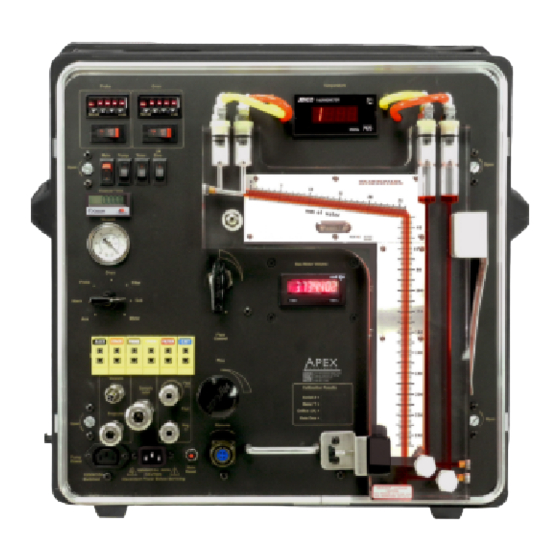
Page 16: Faceplate Components
XC-500 Series Console 2.5 Faceplate Components Reference the image below for an introduction to the essential components of the XC-500 Series Source Sampling console. For specific part numbers and a detailed look at the internal components, go to Sections 6.3 and 6.4 on pages 35 and 36 of this manual. -
Page 17: Operation
XC-500 Series Console 3.0 Console Operation 3.1 User Control Overview 3.1.1 General overview The components on the XC-522, XC-523, and XC-572 consoles allow the operator to control and monitor the sample parameters. Power Switches: Individual power switches used to turn on the console, turn on the external sample pump, turn on the timer, turn on the solenoid valves used to zero the manometer pressure during a sample run, and turn on the AUX power utilized by the AUX power out on the front of the console. -
Page 18: Pre-Field Test Operations
XC-500 Series Console 3.2 Pre-Field Test Operations 3.2.1 Console configuration Ensure that the console has been inspected and is suitable to perform a test run series. The dry gas meter, thermocouple system, and vacuum gauge should all be audited against the most recent calibration. -
Page 19: Console Leak Check Procedure
XC-500 Series Console 3.2.5 Console leak check procedure (front side): 1. Position the valves a. Close the coarse valve by turning the handle clockwise to the horizontal position (”3:00”). b. Decrease the fine tune knob fully by turning all the way to the left (counter- clockwise). -
Page 20: Sample Train Leak Check Procedure
XC-500 Series Console 3.2.6 Sample train leak check procedure A leak check before the sampling run is recommended, but not required. 1. Close the coarse valve by rotating the handle 1/4 turn right (clockwise) until it is horizontal or the arrow is pointing to “3:00.” Decrease the fine tune knob by rotating all the way to the left (counterclockwise). -
Page 21: Field Test Operations
XC-500 Series Console 3.3 Field Test Operations 3.3.1 Performing a Method 5 sampling test This operation guide is written based on US EPA Method 5 sampling. Ensure that you follow the appropriate procedures outlined in the applicable isokinetic method to be performed. EPA Methods 1, 2, and 4 should already be performed and an approximation of Method 3 should be made or measured. -
Page 22: Post-Test Field Operations
XC-500 Series Console 3.4 Post-Field Test Operations 3.4.1 Post-test calibration check After each field test series, conduct a calibration check using the procedures outlined in EPA Method 5, Section 10.3.2 (or Section 16.3), noting that three calibration runs at a single, intermediate orifice setting (based on the previous field test) with the vacuum set at the maximum value reached during... -
Page 23: Setting The Temperature Controller
XC-500 Series Console 3.5 Setting the Temperature Controller 3.5.1 Set value setting 1. The current temperature of the equipment is °C shown on the Fuji controller. To change the set value (SV) press once. 2. Current value is displayed and SV is lit. Press to increase or decrease the displayed value (set value). -
Page 24: Maintenance
XC-572: DGMC-5A-HFM 4.1.2 Initial end user audits Apex Instruments suggests that the end user perform audits on the dry gas meter, thermocouples, vacuum gauge and pressure sensors before performing a field test (post-test calibrations fulfill this suggestion). Perform an audit using a critical orifice set (rated for the intended sampling flow rates) plugged in to the sample inlet on the console. -
Page 25: Post-Test Calibrations
XC-500 Series Console 4.2 Post-Test Calibrations 4.2.1 Dry gas meter Apex Instruments and the EPA recommends that the user perform post-test audits following a field test series using the procedures outlined in EPA Method 5, Section 10.3.2 Calibration After Use . -
Page 26: Post-Test Maintenance
4.5 Annual Maintenance Apex Instruments highly recommends that the console be returned to Apex Instruments on an annual basis. The Technical Services Group will perform an evaluation of all components of the system including functionality and build-integrity checks. All sensors and the dry gas meter can also be calibrated at this time. -
Page 27: Manufacturer Support For The Product
4.6.2 Calibration services Apex Instruments offers dedicated, climate-controlled precision calibration services for a variety of measuring instruments to help keep all equipment up to date and within US EPA calibration requirements. Calibration services are available for consoles, reference meters, critical orifice, orifice sets, pitot tubes (geometric and wind tunnel) and thermocouple simulators. -
Page 28: Troubleshooting
XC-500 Series Console 5.0 Troubleshooting 5.1 Screens and Displays 5.1.1 No power to Jenco temperature display screen CAUTION 1. Connector or wires in the bottom-right corner of the rear of the temperature display unit are not secure Resolution - Ensure that all wires are firmly clamped inside of the connector and that the connector is plugged into the unit 2. -
Page 29: Pressures
XC-500 Series Console 5.2 Pressures 5.2.1 Vacuum gauge non-zero CAUTION 1. Vacuum gauge reads a non-zero value with no flow going through the system Resolution - Replace the vacuum gauge Resolution - Check the tubing connections between the inlet to the console and the vacuum gauge 5.2.2 P reading is changing quickly and is difficult to read... -
Page 30: Temperatures
XC-500 Series Console 5.3 Temperatures 5.3.1 TC displayed values are changing too quickly to read 1. TC values are too sporadic Resolution - Check that wires are not loose anywhere between the TC jacks, temperature selector rotary switch, temperature controller, and temperature display. -
Page 31: Additional Common Console Problems
XC-500 Series Console 5.4 Additional Common Console Problems CAUTION Issue Resolution - Filters are dirty and need to be replaced Maximum vacuum or flow rate - Obstruction in sample flow path decreases - Blockage or kinks in plumbing - Leak in console plumbing or sample train... -
Page 32: Diagrams And Schematics
XC-500 Series Console 6.0 Diagrams and Schematics 6.1 Electrical Diagram (XC-522 120V Shown) 15A/120V TIMER SWITCH BLACK PURPLE MAIN POWER SWITCH CROUZET TIMER 1 2 3 4 5 6 7 8 MC-T M-BUS12W JUMPER JUMPER JUMPER JUMPER (INTERNALLY POWERED) ORANGE... -
Page 33: Plumbing Diagram
XC-500 Series Console 6.2 Plumbing Diagram Fig. 8 Plumbing Diagram Apex Instruments, Inc. -
Page 34: Parts List - Front Panel
XC-500 Series Console 6.3 Parts List - Front Panel (XC-522 120V Shown) 1. XC-CS500 2. TC-765KF 22. M-PXR3-F (x2) 21. M-RA911 (x4) 3. TV-5/3RD TV-5/3YL 20. MC-T7511 Pressure tubing 19. G301U 4. M-42210 Manometer 18. M-31302A-A500 17. TC-PJU (x6) 5. DGM-110* 16. -
Page 35: Parts List - Interior
XC-500 Series Console 6.4 Parts List - Interior (XC-522 120V Shown) 7. M-U8356-120V (x2) ΔH zero solenoid valves 1. TTHV-4-040W 1/4” tubing 6. M-OT10 Venturi-style orifice tube 5. TV-4/2 (x3) 1/4” tubing 2. WK-PP-24 (x9) Thermocouple wire 3. TTHV-6/4 (x6) 3/8”... -
Page 36: References And Related Documentation
Method 3 Method 4 Method 5 Method 17 Method 23 Method 26A Method 29 Method 201A Method 202 Code of Federal Regulations (CFR) 40 Part 60 7.2 Related Documentation 7.2.1 Apex Instruments documentation Apex Instruments Isokinetic Sampling Handbook Apex Instruments, Inc. -
Page 39: Equations And Nomenclature
XC-500 Series Console 7.3 Equations and Nomenclature 7.3.1 Equations Apex Instruments, Inc. -
Page 40: Nomenclature
XC-500 Series Console 7.3.2 Nomenclature actual cubic feet standard absolute pressure (29.92 in Hg) acfm actual cubic feet per minute absolute pressure in flue in inches effective area of flue in square feet (millimeters) mercury actual cubic meters static pressure in flue in inches water,... - Page 41 XC-500 Series Console [THIS PAGE IS INTENTIONALLY LEFT BLANK] Apex Instruments, Inc.
Need help?
Do you have a question about the XC-500 Series and is the answer not in the manual?
Questions and answers