Table of Contents
Advertisement
Quick Links
Advertisement
Table of Contents

Related Manuals for Apex Instruments XC-5000


Summary of Contents for Apex Instruments XC-5000
- Page 1 APEX INSTRUMENTS, INC. Source Sampling Console Manual XC-5000 Operator’s Manual...
- Page 2 XC-5000 204 Technology Park Lane Fuquay-Varina, NC 27526 www.apexinst.com (919) 557-7300 (800) 882-3214 For Support or Service Contact: Technical Services Group support@apexinst.com (877) 726-3919 XC-5000 Operators Manual Revision Date: 2.7.18...
- Page 3 During the warranty period, we will replace or repair, at our option, any new component failing due to a defect in materials or workmanship under normal use and service after proper use. Contact Apex Instruments to receive a return merchandise authorization. Properly label and package the component and return to: Apex Instruments, Inc.
-
Page 4: Table Of Contents
Preliminary Determinations Verification/Nozzle Size Selection............20 K-Factor Calculation ........................21 Sampling Run Procedure ......................... 22 Recommended Reading List for Isokinetic Sampling Recommended Reading List ......................26 System Calibration and Audits Calibration Procedures ........................27 Audit Procedures ..........................35 APEX INSTRUMENTS, INC. - Page 5 XC-5000 Tables Table 1 - USEPA Test Methods Applicable to XC-5000 Source Monitoring Console .......... 1 Table 2 -XC-5000 Application– Associated US EPA Test Methods ..............2 Table 3 - System Features and Specifications ..................... 5 Figures Figure 1 - XC-5000 Source Sampling Train ......................3 Figure 2 - XC-5000 Source Sampling Console ....................
-
Page 6: Table 1- Usepa Test Methods Applicable To Xc-5000 Source Monitoring Console
XC-5000 1 Introduction 1.1 The purpose of this manual is to provide a basic understanding of the Apex Instruments Model XC-5000 Source Sampler Console. Sections of the manual include System Description, Calibration Procedures, Sampling Procedures as well as Maintenance and Troubleshooting Guides. The manual is based on the procedures established by the United States Environmental Protection Agency (USEPA) in accordance with Reference Methods 1 through 5- Determination of Particulate Emissions from Stationary Sources. -
Page 7: Table 2 -Xc-5000 Application- Associated Us Epa Test Methods
XC-5000 The Model XC-5000 Series Sampling System can be configured to perform the following isokinetic test methods and pollutants: Table 2 - XC- 5000 Application – Associated USEPA Test Methods Method No. Pollutants PM from Asphalt Roofing Non-sulfuric Acid PM... -
Page 8: System Description
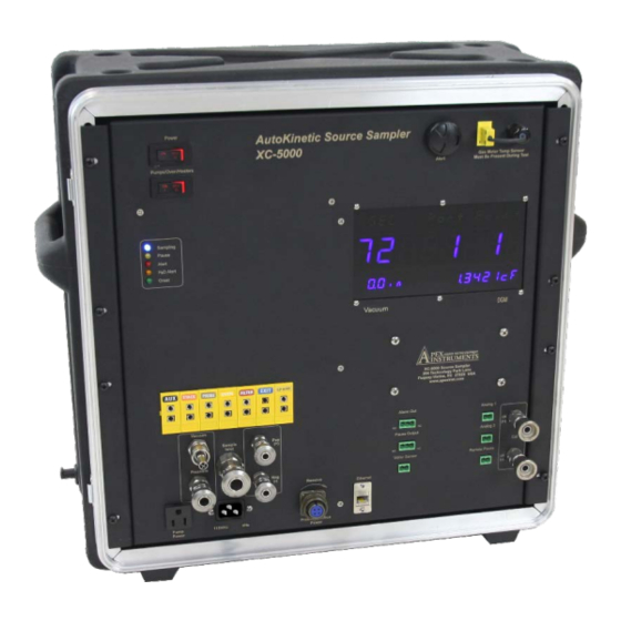
XC-5000 2 System Description The Apex Instruments isokinetic source sampling system consists of five (5) main components, shown in Figure 1-1: 1. Source Sampler Console which includes dual digital pressure sensors, automated flow control valves with orifice flow meter, dry gas meter, and electrical controls. The Console is housed in a weather resistant ultra high molecular weight polyethylene (UHMW) custom designed case complete with carry strap. -
Page 9: Table 3- System Features And Specifications
Console: 23” x 21” x 12” (58 mm x 523 mm x 30.5 mm). Weight Console: 39 lb (17.7 kg). Power Console: 120V / 60 Hz 220V / 50 Hz (optional), 15 A max (includes pump, probe and umbilical heaters). Pump: 120V / 60 Hz 220V / 50 Hz (optional). APEX INSTRUMENTS, INC. -
Page 10: User Interface Software
2.2 User Interface Software The configuration and operation of the XC- 5000 is completely controlled through the system’s User Interface software and the operating system running on the XC-5000 embedded computer resident on the Console’s mother board. The software is constructed to provide a convenient, reliable and consistent methodology for all operations and basically leads the user through the process of performing a test. -
Page 11: Software And Firmware Installation/Upgrade
2.3 Software and Firmware Installation/Upgrade XC-5000 software is composed of two parts the PC application and the firmware that controls the XC-5000. The version number is also made up of two parts. An example would be 70605 -1246. The numbers to the left (70605) of the –is the PC application and the numbers to the right (1246) are for the console firmware. -
Page 12: Figure 5- Config/Utilities Window
By default, all data and audit files created by the XC -5000 software d u ring a test will be stored in the C:\ Apex_5 folder. Make sure the PC and laptop are powered on and connect the PC to XC-5000 with Ethernet cable. Double click the desktop icon to launch the application. -
Page 13: Figure 6 - Firmware File Selection Window
Navigate to the C:\ Apex_5 folder if not there by default. Select the Main firmware 5_Mainxxx.hex where xxx is the version number. Select Open Figure 6 Firmware File Selection C:\ Apex_5 Folder Figure 7 Firmware Upload Successful Window The PC will automatically connect to the XC-5000. APEX INSTRUMENTS, INC. -
Page 14: Electrical Subsystem
• The PUMP/OVEN/HEATERS POWER is activated via the PUMP POWER switch on the Console’s front panel and then controlled by the XC -5000 software. Setpoints are established during the test setup. Figure 8- "Monitor" Window APEX INSTRUMENTS, INC. -
Page 15: Thermocouple Subsystem
All thermocouple readings are displayed on the “Monitor” screen, shown in Figure 4. 2.6 Vacuum SubSystem The vacuum subsystem consists of an external vacuum pump assembly, quick-connects, internal fittings, two (2) control valves (Coarse and Fine), an orifice meter and digital pressure sensors. APEX INSTRUMENTS, INC. -
Page 16: Figure 10 - Monitor Window
A calibrated Orifice Tube located on the outlet of the Dry Gas Meter, indicates the sample flow rate. The orifice pressure drop is displayed in the XC-5000 User Interface “Monitor” window. The stack gas velocity pressure drop is also measured using its own dedicated digital pressure sensor. The instrument sample flow control can be managed either automatically by the system software or manually by the operator. -
Page 17: Operating Procedures For Conducting A Test
USEPA method requirements. By accurately completing required user input data and conducting the test according to method protocols, the XC-5000 ensures the completion of a valid test run. During the conduct of the test, the software performs all required calculations and automatically monitors the status of all system sensors and operating parameters and also provides operator prompts, for example, when to change the test point location. -
Page 18: Establish Communications
XC-5000 3.1 Establish Communications a) Turn on the XC-5000 Main Power Switch and allow console to fully initialize. The display will show the currently installed firmware. Verify it corresponds with the PC software version. b) Connect an Ethernet cable between your computer and the XC- 5000 Console. Once the... -
Page 19: Attach Pre-Console Audit
Note: The Pre-Console Audit is generally performed in the laboratory or instrument shop prior to transporting the system to the test site. Instructions for conducting the audit are provided in Chapter 5 - System Calibration and Audits. APEX INSTRUMENTS, INC. -
Page 20: Complete Other Pre-Test Data - Method 3 And Method 4
When all data has been entered press the button. NOTE: The Heater Control option is used in special cases where the oven temperature is used instead of the filter temperature control. Normally this is off (unchecked) APEX INSTRUMENTS, INC. -
Page 21: Method1- Determining Sample Velocity Traverse Points
Figure 15 – Method 1 Traverse Points Required Figure 16 - Top Section of Method 1 Menu Screen b) If any data are already displayed in this menu’s user input fields, it can be modified by either APEX INSTRUMENTS, INC. -
Page 22: Figure 17 - Method 1 Menu Windows
Enter the distances to the Downstream and Upstream Disturbances. The XC-5000 software will then calculate the stack area, the stack diameter, and the number of diameters to the upstream and downstream disturbances. If the distances to either the upstream or downstream disturbances do not meet the “8 and 2”... -
Page 23: Figure 18 - Bottom Section Method 1 Menu Window
Mark the probe as indicated in the Order of Traverse Points (TP) panel. Note that you will have to scroll down this panel to access complete traverse point information. When all entries in the Method 1 Menu have been completed, click to store the data in the program and return to the main menu. APEX INSTRUMENTS, INC. -
Page 24: Method 2- Stack Gas Velocity And Volumetric Flow Rate
Ts – Stack gas absolute temperature and Delta P Average: These values will be automatically filled in. iii) Ps – Stack gas absolute pressure: If this value is known, it can be entered into the input field directly. Alternatively, pressing the button to perform and enter live values. APEX INSTRUMENTS, INC. -
Page 25: Preliminary Determinations Verification/Nozzle Size Selection
3.7 Preliminary Determinations Verification/Nozzle Size Selection Method 5 provides several techniques for calculating the probe nozzle size and K-factor (ratio of ∆ H/∆ p) needed for isokinetic sampling rate. The XC-5000 User Interface software automatically performs all of the required calculations. -
Page 26: K-Factor Calculation
field where the actual nozzle size (e.g., nozzle diameter) is entered. The XC-5000 automatically calculates the Desired nozzle size and reports it in the field labeled “Calculated Nozzle Size” using the data for each parameter as displayed on this Menu screen. -
Page 27: Sampling Run Procedure
Review all parameter information and selections. When satisfied, click the button to store the K-factor information in the XC-5000 program and return to the Main Menu. Proceed to the next section, Sample Run Procedure, to continue performing a test. -
Page 28: Figure 23 - Leak Test Menu Window
If the leak rate is acceptable, the “Current Flow” and “Vac” boxes will display GREEN. Click on button, the XC-5000 will then prompt you “to complete the leak test, SLOWLY remove plug from the probe and THEN click “Stop Test”. Click the “OK” button, (if the plug is removed too quickly the release of vacuum will pull fluid from the impingers back into the system.) -
Page 29: Figure 24 - Monitoring Menu/Display Window
Traverse the stack cross-section for the same time period at each point without turning off the pump except when changing ports. Do not bump the probe nozzle into the stack walls. Periodically check all system parameters to ensure that the Console is operating properly and all parameters are maintained within specifications. APEX INSTRUMENTS, INC. -
Page 30: Figure 25 - Leak Test Menu Window
The instrument will automatically finish recording all sampling parameter data to the XC-5000. The Monitor Menu will close and the software will return the user to the Main Menu. The Monitor Scree will close and the software will return the user to the Leak Test Screen. -
Page 31: Recommended Reading List For Isokinetic Sampling
Methods, Section 3.4. U.S. Environmental Protection Agency. EPA-600/4-77-027b. 1988. Rom, J. J. Maintenance, Calibration, and Operation of Isokinetic Source Sampling Equipment. Publication No. APTD-0576. Office of Air Programs. U.S. Environmental Protection Agency. Research Triangle Park, NC 1972 APEX INSTRUMENTS, INC. -
Page 32: System Calibration And Audits
firmware will then be displayed with the software version. Also, the Main Menu will show the current date and time in the lower left-hand portion of the menu. b. When connection is made, click on <Config/Utilities> button. APEX INSTRUMENTS, INC. - Page 33 2. Config/Utility Screen a. To perform a System Calibration: click on <Calibrations> button. Other items on this screen: <Set clock> – XC-5000 date / time will be set to the date and time on computer connected to XC- 5000. <Console Audit> – See Console Audit Procedure iii.
- Page 34 Thermocouple same steps as described in a- Connectors The DGM Thermocouple is located at the top right side of the XC-5000 face plate for easy access. Plug the Thermocouple “mini” plug into the “mini” plug jack. APEX INSTRUMENTS, INC.
- Page 35 ) to accept the Current ADC value. Remove the syringe/tubing/ reference manometer apparatus. When the “Zero” ADC value stabilizes, enter the reference meter value in the “Zero” reference value field. Click the <Accept> button ( to accept the current ADC value. APEX INSTRUMENTS, INC.
- Page 36 When the current value is in the chosen range and stable, click the button to accept the current ADC value. Remove the syringe/tubing/Pressure Reference Device and allow the Delta H current value to stabilize, then press the button to accept the ADC value. APEX INSTRUMENTS, INC.
- Page 37 Field Pressure Reading Turn the pump off, release the pressure and wait for the “Current Value” to stabilize. It should be near zero. When the “Current Value” is stable, click the button to accept. APEX INSTRUMENTS, INC.
- Page 38 This field is not a variable. The factor for current meters is always 1.000. Please consult Apex support if you have any questions about the correct setting for your system APEX INSTRUMENTS, INC.
- Page 39 9. Saving Calibration Data Password When all desired sensor Field calibrations are completed, press button at the bottom right hand side of this screen. This will store all sensor calibrations to the system's calibration data table. Save Button APEX INSTRUMENTS, INC.
-
Page 40: Audit Procedures
To access the Audit Menu from the Menu screen, connect to the instrument, then click the Config/Utilities button. Connect/ Disconnect Button Config/ Utilities Button Click the Console Audit button on the Config/Utilities Menu screen Console Audit Button APEX INSTRUMENTS, INC. - Page 41 No further user input is required for the program to recognize the result of the audit point. APEX INSTRUMENTS, INC.
- Page 42 “Enable Auto Accept”. 3) Click on the “Audit By:” field and enter “Enable Auto Accept” the auditor's name / identification. Checkbox APEX INSTRUMENTS, INC.
- Page 43 Fail and the difference between the stack thermocouple and the reference device measurements iii) Proceed to audit the other thermocouples in a similar manner by subjecting the thermocouple being audited and the reference temperature device, simultaneously, to the same temperature environment. APEX INSTRUMENTS, INC.
- Page 44 Note: If any thermocouples do not pass the audit, verify that all thermocouple signal connections have been properly made. If the sensor and signal cabling appear to be in order, the sensor must be recalibrated following the procedure provided in the Meter Calibration section. APEX INSTRUMENTS, INC.
- Page 45 Note: If the sensor doesn't pass, check the audit devices and connections, verify that there are no leaks in either the audit devices or the XC-5000 pneumatic connections between the front panel quick connect fitting and the pressure sensor, then retest. If the result is still not within audit specifications, please contact...
- Page 46 38.1 mm Hg). (Note: A positive pressure must be generated in order to obtain the proper sensor response.) ii) When the reference meter is stable, enter the reference meter value in the Neg. Lo “Ref. Value” field APEX INSTRUMENTS, INC.
- Page 47 O (101.6 – 114.3 mm Hg). ii) When the reference meter is stable, enter the reference meter value in the Neg. High “Ref. Value” field. iii) The results of the audit will be displayed with the message “Pass” or ” -----“. APEX INSTRUMENTS, INC.
- Page 48 Open the Console's Main Control Valve. ii) Turn the sample pump on and slowly close valve attached the sample inlet until the desired pressure is attained, e.g., approximately 5.4 – 6.75 in. O(137.2 – 171.4 mm H APEX INSTRUMENTS, INC.
- Page 49 Allow the Reference Pressure Device reading to stabilize, then enter that reading into the “Lo” Ref. Value field. The results of the Hi Delta H audit will be displayed with the message “Pass” or ” -----“. APEX INSTRUMENTS, INC.
- Page 50 <Accept> Button Value field. b) Connect the sample pump to the Pump quick connect on the front panel of the XC-5000 Console. c) Configure a control valve with a Reference Pressure Device and connect the apparatus to the Sample Inlet Port.
- Page 51 Flow Reference Device, connect the temperature sensor output to the Aux. Thermocouple input on the front panel of the XC-5000 and click the check box for the “Aux TC input for APEX INSTRUMENTS, INC.
- Page 52 Audit files are saved with the .csv extension. The audit file can also be saved to a .jpg file by clicking By default, the audit file is saved to the c:\apex_5 folder. APEX INSTRUMENTS, INC.
Need help?
Do you have a question about the XC-5000 and is the answer not in the manual?
Questions and answers