Table of Contents
Advertisement
Quick Links
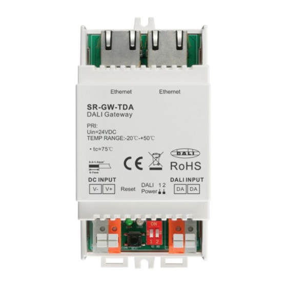
DIN Rail Ethernet (IP) DALI Gateway
2
Important: Read All Instructions Prior to Installation
Function introduction
DALI Gateway
Power indicator
24VDC Input
Reset Key: Long press it to help withdraw
the device from Internet/APP.
Product Data
While built-in DALI PS enabled
Input
Number of
Output
Output
Voltage
Voltage
Current
DALI Channel
1
12-22.5VDC
250mA max
24VDC
While built-in DALI PS disabled
Input
Number of
DALI Current
Voltage
DALI Channel
Consumption
24VDC
1
Max. 2mA
Safety & Warnings
• DO NOT install with power applied to device.
• DO NOT expose the device to moisture.
• Supports DT6, DT8 Tc, DT8 XY, DT8 RGBWA device types
• Supports
addressing
, grouping and scene configuration for max. 64 control gears (DALI-1 and DALI-2)
• Built-in 250mA DALI PS, no extra wiring required
• Easy connect to a network through Ethernet connection
• Easy & quick configuration through the mobile application
RJ45 Terminal
8
7
6
5
4
3
2
1
Prog. indicator:It turns to blue
during reset
1
2
DALI Output/Input
1
2
Enable or disable to
Disabled
use built-in DALI PS
Enabled
by dial switches:
Ambient
Size(LxWxH)
Temperature
110x53x65mm
-20℃ ~ +50℃
Ambient
Size(LxWxH)
Temperature
110x53x65mm
-20℃ ~ +50℃
• Built-in battery, built-in RTC, supports timer task configuration
• Supports cycle schedule configuration,Circadian rhythm function is enabled
• Waterproof grade: IP20
• 5 years warranty
Wiring Diagram
1) While built-in DALI PS enabled
Router
L
N G
L
V -
24V
N
CV PSU
V+
G
Note: When built-in DALI Bus PS is enabled, a DALI gateway can supports up to 64 control gears.
DALI Gateway
DALI Gateway
1
2
1
2
DA
DALI DT6 Control Gear
DA
DA
DALI DT6 Control Gear
DA
DA
DALI DT8 Control Gear
DA
Advertisement
Table of Contents

Related Manuals for Sunricher SR-GW-TDA


Summary of Contents for Sunricher SR-GW-TDA
- Page 1 DIN Rail Ethernet (IP) DALI Gateway • Built-in battery, built-in RTC, supports timer task configuration • Supports cycle schedule configuration,Circadian rhythm function is enabled • Waterproof grade: IP20 • 5 years warranty Important: Read All Instructions Prior to Installation Wiring Diagram Function introduction 1) While built-in DALI PS enabled RJ45 Terminal...
- Page 2 2) While built-in DALI PS disabled Step 1: Download the APP (searching “Lighting APP Goldsmart)” from App Store and Google Play) and set up an accou Then open the APP and add the gateway to the network. Router Tap “Gateway” Download “Lighting APP Goldsmart”...
- Page 3 Step 7: Task setting, you can add tasks with any devices or groups, and run previous scene settings Step 4: All devices have been found, then add it to a certain area, and click the device name into control page. You can add tasks You can add tasks to any devices...
- Page 4 Tips 1. Working with Universal DALI control gears (Both for DALI-1 & DALI-2) 2. Working with SUNRICHER DALI-2 Input devices such as DALI-2 Keypad & DALI-2 Sensor) 3. Better performance with SUNRICHER DALI devices 4. Broadcasting is supported with DALI input devices (careful with DALI bus power)...
Need help?
Do you have a question about the SR-GW-TDA and is the answer not in the manual?
Questions and answers