
Related Manuals for Dynisco ATC990


Summary of Contents for Dynisco ATC990
- Page 1 ATC990 Graphical Controller and UPR900 Process Indicator with optional USB & Data Logging User Manual Drawing Number: 974158...
- Page 3 Dynisco Dynisco Plastics .
- Page 4 Buyer’s sole remedy, and Dynisco’s entire liability, for breach of the foregoing warranty shall be the repair or replacement, at Dynisco’s option, of the the foregoing warranty shall be the repair or replacement, at Dynisco’s option, of the the foregoing warranty shall be the repair or replacement, at Dynisco’s option, of the...
- Page 5 WRITTEN OR ORAL, EXPRESS OR IMPLIED, IN FACT OR BY OPE WRITTEN OR ORAL, EXPRESS OR IMPLIED, IN FACT OR BY OPERATION OF LAW, RATION OF LAW, STATUTORY OR OTHERWISE, INCLUDING WARRANTIES OF MERCHANTABILITY, STATUTORY OR OTHERWISE, INCLUDING WARRANTIES OF MERCHANTABILITY, STATUTORY OR OTHERWISE, INCLUDING WARRANTIES OF MERCHANTABILITY, FITNESS FOR A PARTICULAR PURPOSE, SATISFACTORY QUALITY, ADHERENCE TO FITNESS FOR A PARTICULAR PURPOSE, SATISFACTORY QUALITY, ADHERENCE TO...
-
Page 6: Warranty And Returns Statement
How to use this manual This manual is structured to give easy access to the information required for all aspects of This manual is structured to give easy access to the information required for all aspects of This manual is structured to give easy access to the information required for all aspects of the installation and use and of the ATC ATC Controller. -
Page 7: Table Of Contents
Contents Page Number: Warranty and Returns Statement ............................. 2 Introduction...................................... 12 Installation ......................................13 Unpacking Installation Panel-Mounting Cleaning Electrical Installation .................................... 15 Installation Considerations AC Power Wiring - Neutral (for 100 Neutral (for 100-264 V AC versions) Wire Isolation Use of Shielded Cable Noise Suppression at Source... - Page 8 Main Menu Entry into the Main Menu ....................................36 Unlock Codes ........................................36 Setup Wizard Manual entry to the Setup Wizard Manual entry to the Setup Wizard ............................37 Supervisor Mode Entry into Supervisor Mode ..........................
- Page 9 Single Control Tuning (PI with Primary Output only) with Primary Output only) or! Bookmark not defined. Dual Control Tuning (PI with Primary and Secondary Outputs) with Primary and Secondary Outputs) or! Bookmark not defined. PI Tuning (Valve, Damper & Speed Control PI Tuning (Valve, Damper &...
- Page 10 Option Slot 4 Parameters Setpoint Parameters or! Bookmark not defined. Control Parameters or! Bookmark not defined. Alarm parameters or! Bookmark not defined. Recorder & Clock Parameters or! Bookmark not defined. Display Parameters or! Bookmark not defined. Instrument Data or! Bookmark not defined. Calibration ........
- Page 11 Band Alarm Value Bar Graphs Bias (Manual Reset) Bumpless Transfer Cascade Control Clock Configuration Communications Write Enable Configuration Menu Contactor Control Configuration Control Deviation Control Action Control Enable/Disable Control Type Controller Controller Mode or! Bookmark not defined. Correcting Variable Current Proportioning Control Custom Display Mode Cycle Time Data Recorder...
- Page 12 Input Span Integral Time Constant Latching Relay Linear Input Linear Output Limit Controller Local Setpoints Lock Codes Logical Combination of Alarms Loop Alarm mADC Main Menu Manual Loop Alarm Time Manual Mode Master & Slave Controllers Minimum Duration Of Change Modbus RTU Modbus TCP Modulating Valve...
- Page 13 Rate Of Change Alarm Recorder Configuration Recorder Option Recorder Menu Relay Remote Setpoint (RSP) Retransmit Output Retransmit Output n Scale Maximum Scale Maximum Retransmit Output n Scale Minimum Scale Minimum Reset To Defaults Reverse Acting Control RS485 Scale Range Upper Limit Scale Range Lower Limit Secondary Proportional Band Self-Tune...
- Page 14 Using Automatic Stand-by Automatic Stand-by Example Finding the Steady State Power Using Stand-by Active Limit Appendix 3 - PC SOFTWARE ..........................71 Using The Software or! Bookmark not defined. Instrument Configuration or! Bookmark not defined. Changing the Start-up Splash Screen up Splash Screen or! Bookmark not defined.
- Page 15 Output Specifications or! Bookmark not defined. Communications or! Bookmark not defined. Display or! Bookmark not defined. Control Loop or! Bookmark not defined. Data Recorder Option or! Bookmark not defined. Alarms or! Bookmark not defined. Conditions For Use or! Bookmark not defined. Standards or! Bookmark not defined.
-
Page 16: Introduction
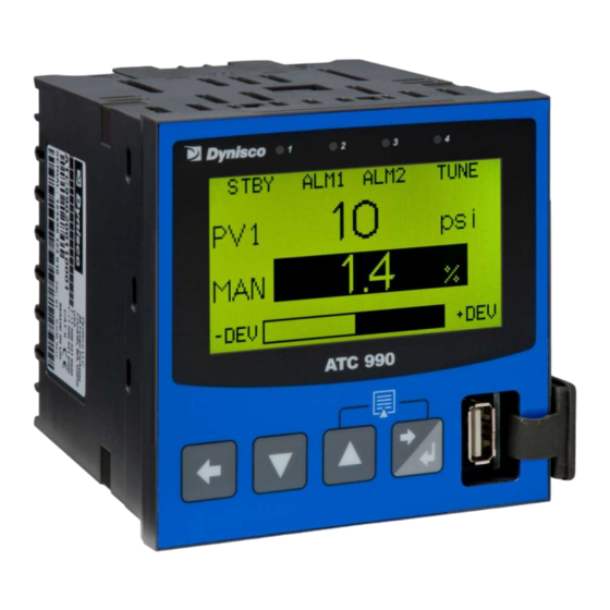
1 Introduction This product is a DIN size (96 x 96mm front) microprocessor based graphical process DIN size (96 x 96mm front) microprocessor based graphical process DIN size (96 x 96mm front) microprocessor based graphical process controller or indicator, featuring a 160 x 80 pixel, monochrome LCD with a dual colour , featuring a 160 x 80 pixel, monochrome LCD with a dual colour , featuring a 160 x 80 pixel, monochrome LCD with a dual colour (red/green) backlight. -
Page 17: Installation
2 Installation Unpacking 1. Remove the product from its packing. Retain the packing for future use, in case it is Remove the product from its packing. Retain the packing for future use, in case it is Remove the product from its packing. Retain the packing for future use, in case it is necessary to transport the instrument to a different site or to return it to the supplier for transport the instrument to a different site or to return it to the supplier for transport the instrument to a different site or to return it to the supplier for... -
Page 18: Cleaning
Instruments may be mounted side-by by-side in a multiple installation, but instrument to panel side in a multiple installation, but instrument to panel moisture and dust sealing will be compromised. Allow a 20mm gap above, below and behind moisture and dust sealing will be compromised. Allow a 20mm gap above, below and moisture and dust sealing will be compromised. -
Page 19: Electrical Installation
3 Electrical Installation Electrical Installation CAUTION: Installation should be only performed by technically competent personnel. It is the Installation should be only performed by technically competent personnel. It i Installation should be only performed by technically competent personnel. It i responsibility of the installing engineer to ensure that the configuration is safe. -
Page 20: Use Of Shielded Cable
Use of Shielded Cable All analogue signals must use shielded cable. This will help elimin All analogue signals must use shielded cable. This will help eliminate electrical noise ate electrical noise induction on the wires. Connection lead length must be kept as short as possible keeping the induction on the wires. -
Page 21: Sensor Placement (Thermocouple Or Rtd)
Sensor Placement (Thermocouple or RTD) Sensor Placement (Thermocouple or RTD) If the temperature probe is to be subjected to co If the temperature probe is to be subjected to corrosive or abrasive conditions, it must be rrosive or abrasive conditions, it must be protected by an appropriate thermowell. -
Page 22: Connections And Wiring
Connections and Wiring This symbol means the equipment is protected throughout by double insulation. This symbol means the equipment is protected throughout by double insulation. This symbol means the equipment is protected throughout by double insulation. CAUTION: All external circuits connected must provide double insulation. Failure to comply All external circuits connected must provide double insulation. -
Page 23: Power Connections
Figure 6. Figure 6. Additional Option terminals Note: Use single strand (1.2mm / AWG18 max size) copper wire throughout, except for the Use single strand (1.2mm / AWG18 max size) copper wire throughout, except for the Use single strand (1.2mm / AWG18 max size) copper wire throughout, except for the thermocouple input, where the correct thermocouple or compensating cable and thermocouple input, where the correct thermocouple or compensating cable and thermocouple input, where the correct thermocouple or compensating cable and... -
Page 24: Universal Input Connections Universal Input Connections
CAUTION: This equipment is designed for installation in an enclosure that provides adequate esigned for installation in an enclosure that provides adequate esigned for installation in an enclosure that provides adequate protection against electric shock. The isolation switch should be located in close protection against electric shock. - Page 25 Figure 9. Figure 9. Strain Gauge Input Connections Universal Input Connections Universal Input Connections – 4-20mA Two-wire Transmitter Powered by Powered by Instrument 24VDC supply is available if and only if Transmitter PSU option card is installed in option 3 24VDC supply is available if and only if Transmitter PSU option card is installed in option 3 24VDC supply is available if and only if Transmitter PSU option card is installed in option 3 slot of the instrument.
- Page 26 Figure 11. Voltage Transmitter Voltage Transmitter Input Connections Universal Input Connections - Thermocouple (T/C) Thermocouple (T/C) Use only the correct thermocouple wire or compensating cable from the probe to the Use only the correct thermocouple wire or compensating cable from the probe to the Use only the correct thermocouple wire or compensating cable from the probe to the instrument terminals avoiding joints in the cable if possible terminals avoiding joints in the cable if possible.
-
Page 27: Option Slot 1 Connections
Option Slot 1 Connections Option Slot 1 – Single Relay Output Module Single Relay Output Module If option slot 1 is fitted with a single relay output module, make connections as illustrated. If option slot 1 is fitted with a single relay output module, make connections as illustrated. If option slot 1 is fitted with a single relay output module, make connections as illustrated. -
Page 28: Option Slot 3 Connections
Figure 16. Option Slot 2 – Single Relay Module Option Slot 2 - Dual Relay Output Module Dual Relay Output Module If option slot 2 is fitted with a dual relay output module, make connections as illustrated. This If option slot 2 is fitted with a dual relay output module, make connections as illustrated. If option slot 2 is fitted with a dual relay output module, make connections as illustrated. -
Page 29: Option Slot A Connections
Figure 19. Option Slot 3 Option Slot 3 - Transmitter Power Supply Module Transmitter Power Supply Module Option Slot A Connections Option Slot A Connections - RS4 RS485 Serial Communications Module If option slot A is fitted with the RS485 serial communication module, connections are as If option slot A is fitted with the RS485 serial communication module, connections are as If option slot A is fitted with the RS485 serial communication module, connections are as illustrated. -
Page 30: Powering Up
(red/green) backlight. The main display typically shows the process variable, set (red/green) backlight. The main display typically shows the process variable, set point/manual power values and a deviation (ATC990) or % of input range bar point/manual power values and a deviation (ATC990) or % of input range bar-graph graph (UPR900). -
Page 31: Led Functions
There are four red LEDs that by default indicate the pressure control status, automatic tuning and alarm 1 & 2 status (ATC990) or Alarm 1, 2 & 3 Status (UPR900). and alarm 1 & 2 status (ATC990) or Alarm 1, 2 & 3 Status (UPR900). The top line of the op line of the graphical display has four labels for LED indicators. - Page 32 Pressing th Pressing the key while holding down the key causes the key causes the instrument to move up one menu level. From Operation Mode and instrument to move up one menu level. From Operation Mode and instrument to move up one menu level. From Operation Mode and in most menus, this will result in entry to the Main Menu.
-
Page 33: Messages And Error Indications Messages And Error Indications
5 Messages and Error Indications Messages and Error Indications Start-up Errors The following displays are shown when an error The following displays are shown when an error is detected during the power detected during the power-up self-test. Option Module Problems The “Option Slot n Error”... -
Page 34: Usb Data Transfer Problems
PV Over-range or Under-range Indication range Indication If the measured process variable value is more than 5% above than the Scale Range Upper If the measured process variable value is more than 5% above than the Scale Range Upper If the measured process variable value is more than 5% above than the Scale Range Upper Limit, its value is replace by the word “... -
Page 35: Configuration And Use
Process Variable Value Engineering Units Engineering Units PV or Setpoint Value Bar Graph: Control -ve Bar Graph: : Control +ve Deviation (ATC990) or Deviation (ATC990) (ATC990) % Input (UPR900) Example Trend View Screen Trend Upper Scale Value Trend Upper Scale Value... - Page 36 Table 3. Table 3. Operation Mode Screens UPR900 Operation Mode: After 2 minutes without key activity, the most screens revert to the Base Operating Screen. After 2 minutes without key activity, the most screens revert to the Base Operating Screen. After 2 minutes without key activity, the most screens revert to the Base Operating Screen.
- Page 37 ATC990 Operation Mode: After 2 minutes without key activity, the most screens revert to the Base Operating Screen. After 2 minutes without key activity, the most screens revert to the Base Operating Screen. After 2 minutes without key activity, the most screens revert to the Base Operating Screen.
-
Page 38: Adjusting The Local Setpoint(S) Adjusting The Local Setpoint(S)
Recording Recorder Log Trigger is Operator Start/Stop. Recorder Log Trigger is Operator Start/Stop. PV1 Trend View An auto An auto-scaling trend graph of Process Variable 1 1 or the Minimum and Maximum value of the Process Variable Minimum and Maximum value of the Process Variable Minimum and Maximum value of the Process Variable 1 measured since the last sample. -
Page 39: Adjusting The Setpoint Ramp Rate Adjusting The Setpoint Ramp Rate
Adjusting the Set point Ramp Rate Ramp Rate The Set point Ramp Rate may be adjusted in the range 0.1 to 9999.0 (in display units per Ramp Rate may be adjusted in the range 0.1 to 9999.0 (in display units per Ramp Rate may be adjusted in the range 0.1 to 9999.0 (in display units per hour) and OFF. -
Page 40: Main Menu
Main Menu This menu is used to access the various features and configuration menus available in the This menu is used to access the various features and configuration menus available in the This menu is used to access the various features and configuration menus available in the instrument. -
Page 41: Setup Wizard
Setup Wizard An easy Setup Wizard runs automatically at first ever power runs automatically at first ever power-up or if whenever a Reset To up or if whenever a Reset To Defaults is carried out. Users can follow the Wizard screens to setup parameters required for Defaults is carried out. -
Page 42: Entry Into Supervisor Mode
Supervisor Mode This mode is only available if it has been This mode is only available if it has been configured from the PC software. The software is configured from the PC software. The software is used to copy up to 50 screens from the Configuration Menus to include in Supervisor Mode. used to copy up to 50 screens from the Configuration Menus to include in Supervisor Mode. -
Page 43: Configuration Menu
Configuration Menu This menu can be used as an alternative to the more limited Setup Wizard when the This menu can be used as an alternative to the more limited Setup Wizard when the This menu can be used as an alternative to the more limited Setup Wizard when the instrument is configured for the first time, or when further changes are required to the first time, or when further changes are required to the first time, or when further changes are required to the... -
Page 44: Hierarchy Chart Of Configuration Menu
Hierarchy Chart of Configuration Menu: Hierarchy Chart of Configuration Menu: Input Type Engineering Units Decimal Point Position Scale Input Range Upper Limits Input 1 Setup Input 1 Setup Scale Input Range Lower Limits Input Filter Time Input Failure Mode Input Peak Detection Input 2 Setup Input 2 Setup Same as Input 1... -
Page 45: Input Configuration Sub-Menu
Input Configuration Sub-Menu Menu Table 8. Input Configuration Sub Input Configuration Sub-Menu Screens Input 1 Setup: From From Strain gauge, various Thermocouple, RTD and Linear inputs. Thermocouple, RTD and Linear inputs. - Input Type see specifications section see specifications section for full details of input types available. for full details of input types available. - Page 46 Input Filter Time Refer to Input1 Input Filter Refer to Input1 Input Filter Time Input Failure Mode Refer to Input1 Failure Mode Refer to Input1 Failure Mode Calibration Reminder: Enables or disables the display of Calibration Reminder at start Enables or disables the display of Calibration Reminder at start Enables or disables the display of Calibration Reminder at start-up Enable/Disable (repeated daily thereafter), if the due date has passed...
- Page 47 SHUNT function is ON and set to the correct percentage (80% for transducer and that the SHUNT function is ON and set to the correct percentage (80% for transducer and that the SHUNT function is ON and set to the correct percentage (80% for a typical Dynisco transducer).
-
Page 48: Control Configuration Sub-Menu
Control Configuration Sub-Menu Menu Table 9. Control Configuration Sub Control Configuration Sub-Menu Screens Control Configuration: Sets the method Sets the method used to enable/disable the control output(s). From: to enable/disable the control output(s). From: Enabled ( Enabled (always); Disabled (always); Enable/Disable via Digital );... - Page 49 Differential 10.0% of Span (centred about set point), when Primary On 10.0% of Span (centred about set point), when Primary On 10.0% of Span (centred about set point), when Primary On-Off control is used. control is used. Enables/disables scaling the Enables/disables scaling the control output as “RPM”...
-
Page 50: Output Configuration Sub-Menu
Output Configuration Sub-Menu Menu Table 10. Output Configuration Output Configuration Sub-Menu Screens Outputs Configuration: Set the desired type for any Linear Outputs fitted. From: 0 Set the desired type for any Linear Outputs fitted. From: 0 Set the desired type for any Linear Outputs fitted. From: 0-5, 0-10, Linear Output n Type 1-5, 2 5, 2-10V &... -
Page 51: Communications Configuration Sub- -Menu
(+ve above, (+ve above, -ve below SP), Band (above or below SP) ve below SP), Band (above or below SP); %Recorder Memory Used; Memory Used; Rate of Signal Change (a rate of more that Rate of Signal Change (a rate of more that x units per hour) or High/Low Power (alarms if control power exceeds this hour) or High/Low Power (alarms if control power exceeds this hour) or High/Low Power (alarms if control power exceeds this... -
Page 52: Clock Configuration Sub-Menu
If recording in progress when Recorder Configuration entered. If recording in progress when Recorder Configuration entered. If recording in progress when Recorder Configuration entered. – Recording In Progress Allows access to the Recording Start/Stop screen only, until the Allows access to the Recording Start/Stop screen only, until the Allows access to the Recording Start/Stop screen only, until the Warning recording is stopped... -
Page 53: Display Configuration Sub-Menu
Sets the internal clock Time. Sets the internal clock Time. - In hh:mm:ss (Hours : Minutes : Hours : Minutes : Set Time Seconds Seconds) format. – Recorder versions only. Display Configuration Sub Display Configuration Sub-Menu Table 15. Display Configuration Sub Display Configuration Sub-Menu Screens Display Configuration: From:... -
Page 54: Lock Code View
Lock Code View Unlock Codes To prevent unauthorised entry, some menus are protected by a lock code. These screens To prevent unauthorised entry, some menus are protected by a lock code. These screens To prevent unauthorised entry, some menus are protected by a lock code. These screens are indicated by the ... -
Page 55: Resetting To Defaults
Resetting To Defaults Table 17. Table 17. Reset To Defaults Sub-Menu Screen Reset To Defaults: Reset To Defaults Sets all parameters to their factory default values. Sets all parameters to their factory default values. If the instrument is to be used in a new or changed application, it is possible to reset all of the If the instrument is to be used in a new or changed application, it is possible to reset all of the If the instrument is to be used in a new or changed application, it is possible to reset all of the instruments parameters back to their factory default settings. -
Page 56: Usb Menu
Table 18. Automatic Tuning Menus Screens Automatic Tuning Menus Screens Automatic Tuning Menu: Automatic Tuning Mode Enter correct code number to access Enter correct code number to access the Automatic Tuning Menu. Automatic Tuning Menu. Unlocking Pre-Tune w Turns Pre Turns Pre-Tune on/off. -
Page 57: Recorder Menu
Transfer Successful Confirmation that the data transfer from the USB stick completed Confirmation that the data transfer from the USB stick completed Confirmation that the data transfer from the USB stick completed correctly. Press to continue correctly. Transfer Failure For read failures, check the maximum number of profiles and/or For read failures, check the maximum number of profiles and/or For read failures, check the maximum number of profiles and/or... -
Page 58: Service Information Mode
Navigating Product Information Mode Navigating Product Information Mode Press to move forward or to move forward or to move backwards through the displayed to move backwards through the displayed information. Hold down and press to return to the Main Menu Scrolling “Help Text”... -
Page 60: The Usb Interface
USB Interface The features in this section are available on models fitted with the optional USB The features in this section are available on models fitted with the optional USB The features in this section are available on models fitted with the optional USB Interface. - Page 61 started or if there is a period of >10s without an alarm when recording from an started or if there is a period of >10s without an alarm when recording from an started or if there is a period of >10s without an alarm when recording from an alarm trigger.
- Page 62 8 Data Recorder The optional Data Recorder allows the The optional Data Recorder allows the recording of process conditions to memory process conditions to memory over time. It operates independently from the Trend Views. over time. It operates independently from the Trend Views. The recorder includes The recorder includes 1Mb of flash memory to store data when powered down and a real tim to store data when powered down and a real time clock...
- Page 63 Uploading Data The data is stored in Comma Separated for Comma Separated format (.csv) which can be transferred to a transferred to a memory stick using the USB Port, then opened and analysed with the optional PC stick using the USB Port, then opened and analysed with the optional PC stick using the USB Port, then opened and analysed with the optional PC software or opened directly into a software or opened directly into a spreadsheet.
- Page 64 9 Tuning Controllers Tuning Controllers 9.1 Automatic tuning The diagram above shows the automatic tuning options / menus available in the The diagram above shows the automatic tuning options / menus available in the The diagram above shows the automatic tuning options / menus available in the controller.
- Page 65 Power up the instrument and if in automatic control Power up the instrument and if in automatic control mode , change to man , change to manual mode at 0% power/0 RPM . Set the alarm types and values as required for your Set the alarm types and values as required for your application (See alarm configuration).
- Page 66 The method of transition from manual to automatic control is set in the control The method of transition from manual to automatic control is set in the control The method of transition from manual to automatic control is set in the control configuration menu.
- Page 67 To deactivate the Self-Tune, deselect run "Self Tune, deselect run "Self-Tune" in the Automatic Tuning Tune" in the Automatic Tuning menu. The self-tune is an on tune is an on-line algorithm that "observes" the measured value and line algorithm that "observes" the measured value and looks for oscillation due to variations of the load or set looks for oscillation due to variations of the load or set-point changes.
- Page 68 allow the controller to give acceptable results in most applications that use a single give acceptable results in most applications that use a single give acceptable results in most applications that use a single control device. CAUTION: This technique is suitable only for processes that are not CAUTION: This technique is suitable only for processes that are not CAUTION: This technique is suitable only for processes that are not harmed by large fluctuations in the process variable.
- Page 69 This tuning technique balances the need to reach setpoint quickly, with the desire This tuning technique balances the need to reach setpoint quickly, with the desire This tuning technique balances the need to reach setpoint quickly, with the desire to limit setpoint overshoot at start to limit setpoint overshoot at start-up and during process changes.
- Page 70 3. Select On-Off control by setting the primary proportional band to zero (the Off control by setting the primary proportional band to zero (the Off control by setting the primary proportional band to zero (the secondary proportional band will automatically be secondary proportional band will automatically be set on-off control when you do off control when you do this).
- Page 71 This tuning method is used when controlling device This tuning method is used when controlling devices such as dampers or s such as dampers or modulating valves with their own valve positioning circuitry. It determines values for modulating valves with their own valve positioning circuitry. It determines values for modulating valves with their own valve positioning circuitry.
- Page 72 START Apply power to the load Time Does the PV continuously oscillate? Note the time Are the interval T Oscillations decaying to zero? P.Pb Multiply Note the period Note the period setting by 1.5 of the decaying of the decaying Int.T &...
- Page 73 Fine Tuning Small adjustments can be made to correct minor control problems. These Small adjustments can be made to correct minor control problems. These Small adjustments can be made to correct minor control problems. These examples assume reverse acting control (e.g. heating). Adjust accordingly for examples assume reverse acting control (e.g.
- Page 74 Proportional Bands Proportional Bands Increase the width of the proportional bands if the process overshoots or oscillates roportional bands if the process overshoots or oscillates roportional bands if the process overshoots or oscillates excessively. Decrease the width of the proportional band if the process responds excessively.
- Page 75 Derivative Time Constant Derivative Time Constant Initially set the derivative to between 1/4 Initially set the derivative to between 1/4 and 1/10 of the Integral time value. of the Integral time value. Increase the derivative time if the process overshoots/undershoots. Increase it a Increase the derivative time if the process overshoots/undershoots.
- Page 76 10 Serial Communications Communications 10.1 Supported Protocols Supported Protocols The unit supports two communication interfaces Modbus RTU and Modbus TCP. The unit supports two communication interfaces Modbus RTU and Modbus TCP. The unit supports two communication interfaces Modbus RTU and Modbus TCP. Modbus RTU is supported through the RS485 interface and Modbus is supported through the RS485 interface and Modbus TCP is TCP is...
- Page 77 10.5 Link Layer A Query (or command) is transmitted from the Modbus Master to the Modbus A Query (or command) is transmitted from the Modbus Master to the Modbus A Query (or command) is transmitted from the Modbus Master to the Modbus Slave.
- Page 78 For a RESPONSE the address field contains the address of the responding For a RESPONSE the address field contains the address of the responding For a RESPONSE the address field contains the address of the responding slave. The Function and Data Data fields are generated by the slave application.
- Page 79 10.6 Supported Modbus Functions Supported Modbus Functions Modbus defines several function function types. The following types are supported supported by this instrument: Function Code Modbus Modbus Meaning Description Description (decimal) 03 / 04 Read Holding/Input Read Holding/Input registers Read current binary value of specified number Read current binary value of specified number of parameters at given address.
- Page 80 Function 06 - Write Single Write Single Register Writes two bytes to a specified word Writes two bytes to a specified word address. QUERY Function Address of Address of Word Value to Value to write RESPONSE Function Address of Address of Word Value written written Note:...
- Page 81 Function 23 Hex - Read / Write Multiple Registers ( Read / Write Multiple Registers (0x17 hex) Reads and writes the requested number of consecutive words (two Reads and writes the requested number of consecutive words (two-bytes) bytes) starting at the specified addresses. addresses.
- Page 82 Function Function Exception Code Original Function code with its Original Function code with its Most as detailed above Significant Bit (MSB) set. Note: In the case of multiple exception exception codes for a single QUERY the Exception code returned returned is the one corresponding to the first first parameter in error.
- Page 83 When working in in Decimal, the format calculations are: are: Address for Integer Integer with 1 Decimal Place = Integer address address plus 16384 Address for Floating Point = Integer 16384 Address for Floating Point = Integer address address multiplied by 2, plus multiplied by 2, plus 32768 Example Register Address Example Register Address Calculations...
- Page 84 Input 1 parameters Modbus Modbus Parameter Access Address Address Notes Default Name (Dec) (Hex) Value Range Input Range 1024 0x0400 B TC C TC D TC E TC J TC K TC L TC N TC R TC S TC T TC Pt100 NI120...
- Page 85 Process 1027 0x0403 Input Range Minimum Process 1028 0x0404 Input Range 10000 Maximum Process 1029 0x0405 Span of the input range Input Process variable offset Process 1030 0x0406 Any value between 0.0 and 512.0 Input Filter time constant Process 1031 0x0407 Input Process...
- Page 86 Display 1061 0x0425 Span of the input range 1000 point 4 Scale point 1062 0x0426 Scale point 4 to 100.0% can only be set when Scale point 4 is not equal to 100.0% Display 1063 0x0427 Span of the input range 1000 point 5 Scale point...
- Page 87 Input Peak 1097 0x0449 0 = Disabled Detection 1 = Maximum Peak 2 = Minimum Peak Peak Value 1101 0x044D Input 1 User Calibration (non Strain Gauge Types) Process 1085 0x043D 0 = No User Calibration Input User 1 = Single Point Calibration Calibration 2 = Two Point Calibration Type...
- Page 88 2. Write “51966” to register 1092 Calibration is attempted 3. Write “2” to register 1094 Selects High Calibration 4. Write “51966” to register 1092 Calibration is attempted It is advisable to read the status between the low and high calibration stages to ensure low cal has completed successfully before performing the high cal Calibration Reminder Calibration...
- Page 89 NI120 0_20mA 4_20mA 0_50mV 10_50mV 0_5V 1_5V 0_10V 2_10V Potentiometer Strain gauge Engineering 1111 0x0457 0 = None units 1 = Degrees C 2 = Degrees F Decimal Place 1112 0x0458 0 = 1234 1 = 123.4 2 = 12.34 3 = 1.234 Process Input 1113...
- Page 90 Scale point 1 1140 0x0474 0.1 to 100.0% Display point 1 1141 0x0475 Span of the input range 1000 Scale point 2 1142 0x0476 Scale point 1 to 100.0% can only be set when Scale point 1 is not equal to 100.0% Display point 2 1143...
- Page 91 Scale point 13 1164 0x048C Scale point 12 to 100.0% can only be set when Scale point 12 is not equal to 100.0% Display point 1165 0x048D Span of the input range 1000 Scale point 14 1166 0x048E Scale point 13 to 100.0% can only be set when Scale point 13 is not equal to 100.0% Display point...
- Page 92 Calibration 1179 0x049B Returns latest calibration status for Input 2: Status 0 = None 1 = Busy 2 = Wait Lo 3 = Wait Hi 4 = Complete 5 = CNT Fail 6 = RCAL Fail Calibration 1180 0x049C Write 1 to Select Input 2 Low Calibration mode Write 2 to Select Input 2 High Calibration Each calibration stage requires two Modbus writes.
- Page 93 Control Loop Input select Up Key Selection mimic Down Key Selection mimic Back Key Selection mimic Right Key Selection mimic Increment Control Output Decrement Control Output As Digital Input A Digital Input 7881 0x1EC9 1 Function Selection Digital Input 7882 0x1ECA As Digital Input A 2 Function...
- Page 94 Option Slot 1 parameters Modbus Modbus Parameter Access Address Address Notes Default Name (Dec) (Hex) Output type 2130 0x0852 0 = No option fitted 1 = Relay255 = Illegal/Invalid Digital Output 2132 0x0854 0 = Inactive state 1 = Active Output 2146 0x0862...
- Page 95 4 = Alarm 1 Reverse Acting 5 = Alarm 2 Direct Acting 6 = Alarm 2 Reverse Acting 7 = Alarm 3 Direct Acting 8 = Alarm 3 Reverse Acting 9 = Alarm 1 Or Alarm 2 Direct Acting 10 = Alarm 1 Or Alarm 2 Reverse Acting 11 = Alarm 1 Or Alarm 2 Or Alarm 3 Direct Acting 12 = Alarm 1 Or Alarm 2 Or Alarm 3...
- Page 96 Output A 2194 0x0892 0 = Inactive state 1 = Active Output A 2205 0x089D 0 = Disabled function 1 = Primary output power selection 2 = Secondary output power 3 = Alarm 1 Direct Acting 4 = Alarm 1 Reverse Acting 5 = Alarm 2 Direct Acting 6 = Alarm 2 Reverse Acting 7 = Alarm 3 Direct Acting...
- Page 97 Linear Output A parameters Modbus Modbus Parameter Access Address Address Notes Default Name (Dec) (Hex) Value Range Linear output 3011 0x0BC3 0 – 5V range 0 – 10V 2 – 10V 0 – 20mA 4 – 20mA 0 – 10V DC Supply Linear Output 2144 0x0860...
- Page 98 Primary Control Power Secondary Control Power Retransmit SP Retransmit Input 1PV Retransmit Input 2PV Retransmit Differential 0 to 10V as a percentage between 0 - 100 0 – 10V DC 3024 0x0BD0 Supply Input 1 2182 0x0886 Retransmit Minimum Input 1 2183 0x0887 Retransmit...
- Page 99 Setpoint parameters (ATC Only) Modbus Modbus Parameter Access Address Address Notes Default Name (Dec) (Hex) Setpoint 3944 0x0F68 Limited by input range maximum/minimum Minimum Setpoint 3945 0x0F69 Limited by input range maximum/minimum 10000 Maximum Setpoint 1A 3960 0x0F78 Limited by Setpoint maximum/minimum Value Setpoint 1A 3961...
- Page 100 Control parameters (ATC Only) Modbus Modbus Access Parameter Name Address Address Notes Default (Dec) (Hex) Primary Cycle Time 4301 0x10CD 0.5 to 512.0 Secondary Cycle 4302 0x10CE 0.5 to 512.0 Time Auto/Manual Control 4308 0x10D4 0 = Automatic 1 = Manual Control 4309 0x10D5...
- Page 101 Self tune Enable 4326 0x10E6 0 = Disabled 1 = Enabled Loop Alarm Type 4327 0x10E7 0 = Off 1 = Time 2 = Auto Loop Alarm time 4328 0x10E8 1 to 5999 Primary Power 4329 0x10E9 0 to 100% Secondary Power 4330 0x10EA...
- Page 102 Alarm parameters Alarm 1 Modbus Modbus Parameter Access Address Address Notes Default Name (Dec) (Hex) Alarm Type 6143 0x17FF 0 = Unused 1 = High Alarm 2 = Low Alarm 3 = Deviation Alarm 4 = Band Alarm 5 = Input Rate of change 6 = Sensor Break Alarm 7 = Control Loop 10 = % Memory Used...
- Page 104 Modbus Modbus Parameter Access Address Address Notes Default Name (Dec) (Hex) Alarm Type 6159 0x180F 0 = Unused 1 = High Alarm 2 = Low Alarm 3 = Deviation Alarm 4 = Band Alarm 5 = Input Rate of change 6 = Sensor Break Alarm 7 = Control Loop 10 = % Memory Used...
- Page 105 Modbus Modbus Parameter Access Address Address Notes Default Name (Dec) (Hex) Alarm Type 6175 0x181F 0 = Unused 1 = High Alarm 2 = Low Alarm 3 = Deviation Alarm 4 = Band Alarm 5 = Input Rate of change 6 = Sensor Break Alarm 7 = Control Loop 10 = % Memory Used...
- Page 107 Logger parameters (Data Logger) Data Recorder Modbus Modbus Parameter Access Address Address Notes Default Name (Dec) (Hex) Log Interval 7550 0x1D7E 0 = Every second 1 = Every 2 seconds 2 = Every 5 seconds 3 = Every 10 seconds 4 = Every 15 seconds 5 = Every 30 seconds 6 = Every Minute...
- Page 108 1 PV Min 1 = Record Record Input 7607 0x1DB7 0 = Off 2 PV 1 = Record Record Input 7608 0x1DB8 0 = Off 2 PV Max 1 = Record Record Input 7609 0x1DB9 0 = Off 2 PV Min 1 = Record Record Local 7575...
- Page 109 Real time clock Modbus Modbus Access Parameter Address Notes Default Address Name (Hex) (Dec) Date 7868 0x1EBC 0 = dd/mm/yyyy (European Default) format 1 = mm/dd/yyyy (USA Default) Time 7869 0x1EBD In seconds from midnight Date 7870 0x1EBE Binary coded decimal (BCD) 16 bits that represent the date as follows: 0000 0000 0000 0000 Month...
- Page 110 Display parameters Keys Modbus Modbus Parameter Access Address Address Notes Default Name (Dec) (Hex) Key State 7669 0x1DF5 Current state of the keys LEDs Modbus Modbus Parameter Access Address Address Notes Default Name (Dec) (Hex) LED 1 Label 7656 0x1DE8 Max 6 charaters STBY LED 2 Label...
- Page 111 Modbus Modbus Parameter Access Address Address Notes Default Name (Dec) (Hex) Language 7675 0x1DFB 0 = Downloaded Language 1 = English LCD Contrast 7676 0x1DFC 0 to 100 Invert LCD 7677 0x1DFD 0 = Normal 1 = Inverted Setup Lock 7678 0x1DFE Default 10...
- Page 112 Parameter Access Address Address Notes Default Name (Dec) (Hex) Contact 0x0190 26 characters of text Dynisco Details line 1 Contact 0x0191 26 characters of text Details line 2 Forge Parkway Contact 0x0192 26 characters of text Franklin, Details line 3...
- Page 113 11 Calibration WARNING: CALIBRATION IS ONLY REQUIRED FOR INSTRUM REQUIRED FOR INSTRUMENTS IN WHICH CALIBRATION ERRORS CALIBRATION ERRORS HAVE BEEN ENCOUNTERED. REFER TO CALIBRAT D. REFER TO CALIBRATION CHECK BELOW. CAUTION: Calibration must be performed by personnel who are technically competent and Calibration must be performed by personnel who are technically competent and Calibration must be performed by personnel who are technically competent and authorised to do so.
- Page 114 Recalibration Procedure Recalibration is carried out in five phases as shown in the Recalibration is carried out in five phases as shown in the table below; each phase below; each phase corresponds to a basic input type. CAUTION: The 50mV phase MUST be calibrated before the thermo The 50mV phase MUST be calibrated before the thermocouple range.
- Page 115 12 Appendix 1 – Glossary of Terms Used Glossary of Terms Used Active Set point The term Active Set point is used to describe the currently selected is used to describe the currently selected set point set point when the instrument is in Controller Mode.
- Page 116 Inactive Inactive Active Figure 23. Figure 23. Alarm Hysteresis Operation PROCESS HIGH Alarm Value Alarm Value ALARM Alarm Hysteresis Value Alarm Hysteresis Value Process Variable Process Variable Alarm Hysteresis Value Alarm Hysteresis Value PROCESS LOW Alarm Value Alarm Value ALARM Inactive Inactive Active...
- Page 117 Alarm Operation The Process and Deviation Alarm types are illustrated, together with the action of any The Process and Deviation Alarm types are illustrated, together with the action of any The Process and Deviation Alarm types are illustrated, together with the action of any associated outputs.
- Page 118 Figure 24. Figure 24. Alarm Operation Alarm Inhibit Alarm Inhibit prevents unwanted process or deviation alarm activation at power-up or when Alarm Inhibit prevents unwanted process or deviation alarm activation at power Alarm Inhibit prevents unwanted process or deviation alarm activation at power the controller set point is changed.
- Page 119 Auxiliary Input A secondary linear input module can be installed. This A secondary linear input module can be installed. This can be used as Remote Remote Set point inputs. Signals can be mA, mV, VDC or Potentiometer. nals can be mA, mV, VDC or Potentiometer. Also refer to: Alternative Set point Set point, Digital Input, Linear Input, mADC, mVDC mVDC, Remote Set...
- Page 120 variable settles below set point use a higher Bias value to remove the error, if the use a higher Bias value to remove the error, if the process use a higher Bias value to remove the error, if the variable settles above the set point use a lower Bias value.
- Page 121 Control, PI, Remote Set point, Auxiliary Input Lower Limit Auxiliary Input Lower Limit, Auxiliary Input Upper Limit Auxiliary Input Upper Limit, Set point, Set point Select, Tuning and and VDC. Clock Configuration A sub-menu of Configuration Mode used to adjust the parameters that relate to the settings menu of Configuration Mode used to adjust the parameters that relate to the settings menu of Configuration Mode used to adjust the parameters that relate to the settings for the Real Time Clock fitted with the data recorder option (Date, time,...
- Page 122 action is always the opposite of the primary output. action is always the opposite of the primary output. Settings = Reverse or Direct Default value = Default value = Reverse. Also refer to: Control Type, Correcting Variable Correcting Variable, Direct Acting Control and Reverse Acting Reverse Acting Control.
- Page 123 screens follow the normal Operation Mode screens. In this mode these screens are not pass- screens follow the normal Operation Mode screens. In this mode these screens are not pass screens follow the normal Operation Mode screens. In this mode these screens are not pass code protected.
- Page 124 An input that can be driven to one of two sta An input that can be driven to one of two states (active or inactive) by and external voltage or tes (active or inactive) by and external voltage or a contact opening/closing. Digital Inputs can be used to set the instrument in to different a contact opening/closing.
- Page 125 Indicator An instrument that displays process values cess values, but lacks control features. Typically, alarm control features. Typically, alarm outputs are available that will activate at preset outputs are available that will activate at preset PV values. Also refer to: Controller, Limit Control Limit Controller and Process Variable.
- Page 126 Latching Relay A type of relay that, once it becomes active, requires a reset signal before it will deactivate. If A type of relay that, once it becomes active, requires a reset signal before it will deactivate. If A type of relay that, once it becomes active, requires a reset signal before it will deactivate. If latching relays are required, they can be fitted externally as slaves to the internal (non- latching relays are required, they can be fitted externally as slaves to the internal (non latching relays are required, they can be fitted externally as slaves to the internal (non...
- Page 127 Settings = 1 to 9999 or OFF. Default value = Default value = 10 Also refer to: Configuration Mode Configuration Mode, Main Menu, Recorder Menu, Setup Wizard Setup Wizard, Supervisor Mode, Tuning Menu and USB Menu USB Menu. Logical Combination of Alarms Logical Combination of Alarms Outputs for alarms may be combined to create a Logical OR situation.
- Page 128 The loop alarm is automatically disabled during manual control mode and during execution of The loop alarm is automatically disabled during manual control mode and during execution of The loop alarm is automatically disabled during manual control mode and during execution of a Pre-Tune.
- Page 129 MUST maintain the process at the desired level manually. Manual power is not limited by the MUST maintain the process at the desired level manually. Manual power is not limited by the MUST maintain the process at the desired level manually. Manual power is not limited by the Power Output Limits.
- Page 130 Also refer to: Modbus TCP, RS485 and Serial Communications. Modbus TCP Modbus TCP is a version of the Modbus protocol for networks that support the Internet TCP is a version of the Modbus protocol for networks that support the Internet TCP is a version of the Modbus protocol for networks that support the Internet Protocol, such as Ethernet.
- Page 131 On-Off Control When operating in On-Off mode, the control output(s) will turn on or off as the process Off mode, the control output(s) will turn on or off as the process Off mode, the control output(s) will turn on or off as the process variable crosses the set point in a manner similar to a central heating thermostat.
- Page 132 The Overlap/Dead band parameter d parameter defines the portion of the primary and secondary efines the portion of the primary and secondary proportional bands over which both outputs are active (called Overlap), or neither is active proportional bands over which both outputs are active (called Overlap), or neither is active proportional bands over which both outputs are active (called Overlap), or neither is active (called Dead band).
- Page 133 OVERLAP Proportional Band 1 WITH PI Proportional Band 2 Output 2 Output 1 Output 1 Output 2 Output 2 Output 1 Process Variable Overlap (positive value) DEADBAND Proportional Proportional WITH PI Band 2 Band 1 Output 1 Output 1 Output 2 Output 2 Output 2 Output 1...
- Page 134 PI Control Proportional Integral control maintains accurate and stable levels in a process (e.g. when Proportional Integral control maintains accurate and stable levels in a process (e.g. when Proportional Integral control maintains accurate and stable levels in a process (e.g. when controlling a temperature).
- Page 135 Setpoint Setpoint Process Variable SP – Initial PV Initial PV Initial PV Initial PV Pre-Tune +100% Power (HEAT output) +100% Power (HEAT output) engaged here Control Power -100% Power (Cool output) 100% Power (Cool output) Figure 26. Figure 26. Pre-Tune Operation When Pre-Tune is completed, the Tune is completed, the PI control output power is applied using the calculated control output power is applied using the calculated...
- Page 136 Primary Proportional Band The portion of the input span over which the Primary Output power level is proportional to the span over which the Primary Output power level is proportional to the span over which the Primary Output power level is proportional to the process variable value.
- Page 137 Process Variable Offset The Process variable offset is used to modify the measured process variable value. Use this The Process variable offset is used to modify the measured process variable value. Use this The Process variable offset is used to modify the measured process variable value. Use this parameter to compensate for errors in the displayed process variable.
- Page 138 Also refer to: Lock Codes, Main Menu Main Menu and Data Recorder Relay An electromechanical switch operated by a solenoid coil. Relays are commonly fitted as An electromechanical switch operated by a solenoid coil. Relays are commonly fitted as An electromechanical switch operated by a solenoid coil. Relays are commonly fitted as internal, time proportioning controller outputs.
- Page 139 Also refer to: Process Variable, Retransmit Output Retransmit Output, Retransmit Output n Scale Maximum Retransmit Output n Scale Maximum, Scale Range Lower Limit and Set point Set point. Reset To Defaults This Configuration sub-menu selection returns all of the instruments settings back to their menu selection returns all of the instruments settings back to their menu selection returns all of the instruments settings back to their factory defaults.
- Page 140 Scale Range Upper Limit For linear inputs, this parameter is used to scale the displaye For linear inputs, this parameter is used to scale the displayed process variable. It defines d process variable. It defines the displayed value when the process variable input is at its maximum value (e.g. if 4 to the displayed value when the process variable input is at its maximum value (e.g.
- Page 141 Setpoint 2 Load Disturbance Setpoint 1 Setpoint Change Time Figure 27. Figure 27. Self-Tune Operation The deviation signal is shown shaded, and overshoots have been exaggerated for clarity. The deviation signal is shown shaded, and overshoots have been exaggerated for clarity. The deviation signal is shown shaded, and overshoots have been exaggerated for clarity.
- Page 142 A feature that allows other devices such as PC’s, PLC’s or a master controller to read, or A feature that allows other devices such as PC’s, PLC’s or a master controller to read, or A feature that allows other devices such as PC’s, PLC’s or a master controller to read, or change the instruments parameters via an RS485 or Ethernet network.
- Page 143 raPI rise in the process variable. Settings = 1 to 9999 LSDs per hour. Settings = 1 to 9999 LSDs per hour. Default Value = OFF Default Value = OFF Also refer to: Active Set point, Actual Actual Set point, LSD, Manual Mode, Process Variable Process Variable, Set point, Set point Ramp Editing and and Set point Selection.
- Page 144 Thermocouple A temperature sensor made from two different metals. They con A temperature sensor made from two different metals. They convert temperature difference vert temperature difference between their cold junction (the measuring instrument) and the hot junction, into a small between their cold junction (the measuring instrument) and the hot junction, into a small between their cold junction (the measuring instrument) and the hot junction, into a small signal or a few microvolts per °C.
- Page 145 Tuning PI Controllers must be tuned to the process in order for them to attain the optimum level of Controllers must be tuned to the process in order for them to attain the optimum level of Controllers must be tuned to the process in order for them to attain the optimum level of control.
- Page 146 This stands for Volts DC. It is used in reference to the linear DC Voltage input ranges. This stands for Volts DC. It is used in reference to the linear DC Voltage input ranges. This stands for Volts DC. It is used in reference to the linear DC Voltage input ranges. Typically, these will be 0 to 5V, 1 to 5V, 0 to 10V Typically, these will be 0 to 5V, 1 to 5V, 0 to 10V or 2 to 10VDC.
- Page 147 13 Appendix 2 – Automatic Stand Automatic Stand-by (ATC990 Only) by (ATC990 Only) Automatic stand-by Feature The automatic stand-by function avoids overshoots following temporary process interruptions by function avoids overshoots following temporary process interruptions by function avoids overshoots following temporary process interruptions (i.e.
- Page 148 **The old model ATC880 monitor the input and output the feature only began if the threshold the feature only began if the threshold was passed and the output was at saturation. ATC990 monitors the input level, but not output the output was at saturation. ATC990 monitors the input level, but not output the output was at saturation.
- Page 149 Using Stand-by Active Limit. In addition to the automatic stand In addition to the automatic stand-by feature itself, further protection to the process is given by feature itself, further protection to the process is given by the Stand-by Active Limit. Its purpose is to limit the output swing possible in very sensitive by Active Limit.
- Page 150 14 Appendix 3 - PC SOFTWARE PC SOFTWARE The primary function of the software is to create, download and store instrument The primary function of the software is to create, download and store instrument The primary function of the software is to create, download and store instrument configurations and profiles.
- Page 151 The Button bar, Device and View menus are used to access the other software functions. The Button bar, Device and View menus are used to access the other software functions. The Button bar, Device and View menus are used to access the other software functions. View &...
- Page 152 A communications settings screen is shown whenever the user attempts to connect to the A communications settings screen is shown whenever the user attempts to connect to the A communications settings screen is shown whenever the user attempts to connect to the instrument from the software.
- Page 153 Connection from PC/Network to Ethernet Port Connection from PC/Network to Ethernet Port When using the optional Ethernet communications, set the parameters as shown here. When using the optional Ethernet communications, set the parameters as shown here. When using the optional Ethernet communications, set the parameters as shown here. ...
- Page 154 Note: You can enter any valid IP address, perhaps for use in another location, You can enter any valid IP address, perhaps for use in another location, You can enter any valid IP address, perhaps for use in another location, but if the number used used does not match your existing network settings settings, further...
- Page 155 device information and configuration parameter settings, including any supervisor and device information and configuration parameter settings, including any supervisor and device information and configuration parameter settings, including any supervisor and enhanced operation mode screens or changes to LED functions. Splash screens and data enhanced operation mode screens or changes to LED functions.
- Page 156 Note: Any parameters copied into the custom display screens are not Any parameters copied into the custom display screens are not Any parameters copied into the custom display screens are not password protected. They can be freely viewed and adjusted by anyone with They can be freely viewed and adjusted by anyone with access to the instrument keypad.
- Page 157 Data Recorder Trend Upload & Analysis Data Recorder Trend Upload & Analysis Uploading Data Recordings can be transferred to a memory stick using the Recordings can be transferred to a memory stick using the optional USB Port USB Port, or they can also be uploaded directly to your PC or network with the directly to your PC or network with the software, via the configuration via the configuration port...
- Page 158 A hard copy of the instrument configuration can be printed from A hard copy of the instrument configuration can be printed from A hard copy of the instrument configuration can be printed from the File | Print menu the File | Print menu. This includes the project information, configuration parameters This includes the project information, configuration parameters This includes the project information, configuration parameters...
Need help?
Do you have a question about the ATC990 and is the answer not in the manual?
Questions and answers